CHRYSLER VOYAGER 2002 Service Manual
Manufacturer: CHRYSLER, Model Year: 2002, Model line: VOYAGER, Model: CHRYSLER VOYAGER 2002Pages: 2399, PDF Size: 57.96 MB
Page 261 of 2399
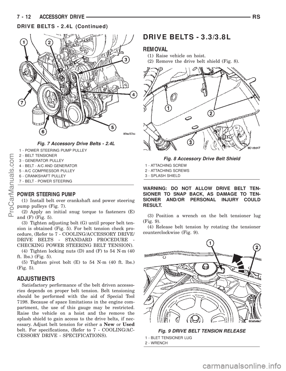
POWER STEERING PUMP
(1) Install belt over crankshaft and power steering
pump pulleys (Fig. 7).
(2) Apply an initial snug torque to fasteners (E)
and (F) (Fig. 5).
(3) Tighten adjusting bolt (G) until proper belt ten-
sion is obtained (Fig. 5). For belt tension check pro-
cedure, (Refer to 7 - COOLING/ACCESSORY DRIVE/
DRIVE BELTS - STANDARD PROCEDURE -
CHECKING POWER STEERING BELT TENSION).
(4) Tighten locking nuts (D) and (F) to 54 N´m (40
ft. lbs.) (Fig. 5).
(5) Tighten pivot bolt (E) to 54 N´m (40 ft. lbs.)
(Fig. 5).
ADJUSTMENTS
Satisfactory performance of the belt driven accesso-
ries depends on proper belt tension. Belt tensioning
should be performed with the aid of Special Tool
7198. Because of space limitations in the engine com-
partment, the use of this gauge may be restricted.
Raise the vehicle on a hoist and the remove the
splash shield to gain access to the drive belts, if nec-
essary. Adjust belt tension for either aNeworUsed
belt. For specifications, (Refer to 7 - COOLING/AC-
CESSORY DRIVE - SPECIFICATIONS).
DRIVE BELTS - 3.3/3.8L
REMOVAL
(1) Raise vehicle on hoist.
(2) Remove the drive belt shield (Fig. 8).
WARNING: DO NOT ALLOW DRIVE BELT TEN-
SIONER TO SNAP BACK, AS DAMAGE TO TEN-
SIONER AND/OR PERSONAL INJURY COULD
RESULT.
(3) Position a wrench on the belt tensioner lug
(Fig. 9).
(4) Release belt tension by rotating the tensioner
counterclockwise (Fig. 9).
Fig. 7 Accessory Drive Belts - 2.4L
1 - POWER STEERING PUMP PULLEY
2 - BELT TENSIONER
3 - GENERATOR PULLEY
4 - BELT - A/C AND GENERATOR
5 - A/C COMPRESSOR PULLEY
6 - CRANKSHAFT PULLEY
7 - BELT - POWER STEERING
Fig. 8 Accessory Drive Belt Shield
1 - ATTACHING SCREW
2 - ATTACHING SCREWS
3 - SPLASH SHIELD
Fig. 9 DRIVE BELT TENSION RELEASE
1 - BLET TENSIONER LUG
2 - WRENCH
7 - 12 ACCESSORY DRIVERS
DRIVE BELTS - 2.4L (Continued)
ProCarManuals.com
Page 262 of 2399
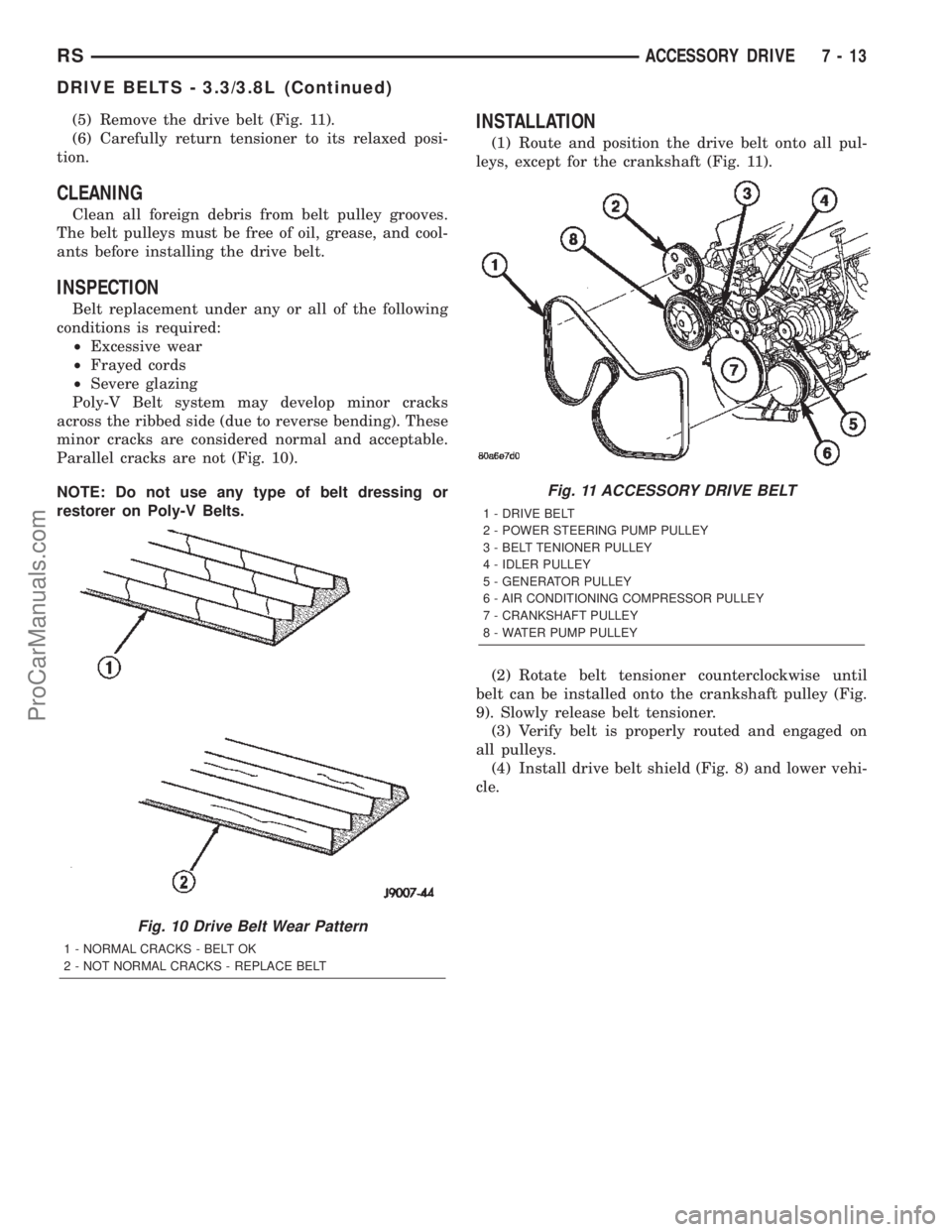
(5) Remove the drive belt (Fig. 11).
(6) Carefully return tensioner to its relaxed posi-
tion.
CLEANING
Clean all foreign debris from belt pulley grooves.
The belt pulleys must be free of oil, grease, and cool-
ants before installing the drive belt.
INSPECTION
Belt replacement under any or all of the following
conditions is required:
²Excessive wear
²Frayed cords
²Severe glazing
Poly-V Belt system may develop minor cracks
across the ribbed side (due to reverse bending). These
minor cracks are considered normal and acceptable.
Parallel cracks are not (Fig. 10).
NOTE: Do not use any type of belt dressing or
restorer on Poly-V Belts.
INSTALLATION
(1) Route and position the drive belt onto all pul-
leys, except for the crankshaft (Fig. 11).
(2) Rotate belt tensioner counterclockwise until
belt can be installed onto the crankshaft pulley (Fig.
9). Slowly release belt tensioner.
(3) Verify belt is properly routed and engaged on
all pulleys.
(4) Install drive belt shield (Fig. 8) and lower vehi-
cle.
Fig. 10 Drive Belt Wear Pattern
1 - NORMAL CRACKS - BELT OK
2 - NOT NORMAL CRACKS - REPLACE BELT
Fig. 11 ACCESSORY DRIVE BELT
1 - DRIVE BELT
2 - POWER STEERING PUMP PULLEY
3 - BELT TENIONER PULLEY
4 - IDLER PULLEY
5 - GENERATOR PULLEY
6 - AIR CONDITIONING COMPRESSOR PULLEY
7 - CRANKSHAFT PULLEY
8 - WATER PUMP PULLEY
RSACCESSORY DRIVE7-13
DRIVE BELTS - 3.3/3.8L (Continued)
ProCarManuals.com
Page 263 of 2399
ENGINE
TABLE OF CONTENTS
page page
ENGINE
DIAGNOSIS AND TESTING - ENGINE
COOLING SYSTEM....................15
CLEANING............................19
INSPECTION..........................19
COOLANT
DIAGNOSIS AND TESTING - COOLANT
CONCENTRATION TESTING.............19
STANDARD PROCEDURE - COOLANT
SERVICE............................20
COOLANT RECOVERY CONTAINER
DESCRIPTION.........................20
OPERATION...........................20
DIAGNOSIS AND TESTING - COOLANT
RECOVERY SYSTEM..................20
REMOVAL.............................20
INSTALLATION.........................20
ENGINE BLOCK HEATER
DESCRIPTION.........................21
OPERATION...........................21
DIAGNOSIS AND TESTING - ENGINE BLOCK
HEATER TESTING.....................21
REMOVAL.............................21
INSTALLATION.........................21
ENGINE COOLANT TEMPERATURE SENSOR -
2.4L
DESCRIPTION.........................21
REMOVAL.............................21
INSTALLATION.........................21
ENGINE COOLANT TEMPERATURE SENSOR -
3.3/3.8L
DESCRIPTION.........................22
REMOVAL.............................22
INSTALLATION.........................22
ENGINE COOLANT THERMOSTAT
DESCRIPTION.........................23
OPERATION...........................23
DIAGNOSIS AND TESTING - ENGINE
COOLANT THERMOSTAT...............23
ENGINE COOLANT THERMOSTAT - 2.4L
REMOVAL.............................23
INSTALLATION.........................23
ENGINE COOLANT THERMOSTAT - 3.3/3.8L
REMOVAL.............................24
INSTALLATION.........................24
RADIATOR
DESCRIPTION.........................25
OPERATION...........................25REMOVAL.............................25
INSTALLATION.........................26
RADIATOR DRAINCOCK
REMOVAL.............................27
INSTALLATION.........................27
RADIATOR PRESSURE CAP
DESCRIPTION.........................27
OPERATION...........................27
DIAGNOSIS AND TESTING
DIAGNOSIS AND TESTING - COOLING
SYSTEM PRESSURE CAP TESTING.......28
DIAGNOSIS AND TESTING - RADIATOR
CAP TO FILLER NECK SEAL.............28
CLEANING............................29
INSPECTION..........................29
RADIATOR FAN
DESCRIPTION.........................29
OPERATION...........................29
DIAGNOSIS AND TESTING - RADIATOR FAN
MOTOR .............................30
REMOVAL.............................30
INSTALLATION.........................30
RADIATOR FAN RELAY
DESCRIPTION.........................31
OPERATION...........................31
REMOVAL.............................31
INSTALLATION.........................31
WATER PUMP - 2.4L
DESCRIPTION.........................32
OPERATION...........................32
REMOVAL.............................32
CLEANING............................32
INSPECTION..........................32
INSTALLATION.........................32
WATER PUMP - 3.3/3.8L
DESCRIPTION.........................34
OPERATION...........................34
REMOVAL.............................34
CLEANING............................35
INSPECTION..........................35
INSTALLATION.........................35
WATER PUMP INLET TUBE - 2.4L
DESCRIPTION.........................36
REMOVAL.............................36
INSTALLATION.........................36
WATER PUMP INLET TUBE - 3.3/3.8L
REMOVAL.............................36
INSTALLATION.........................36
7 - 14 ENGINERS
ProCarManuals.com
Page 264 of 2399
ENGINE
DIAGNOSIS AND TESTING - ENGINE COOLING
SYSTEM
Establish what driving condition caused the cooling
system complaint. The problem may be caused by an
abnormal load on the system such as the following:
prolonged idle, very high ambient temperature, slight
tail wind at idle, slow traffic speed, traffic jam, high
speed, steep grade.
DRIVING TECHNIQUES
To avoid overheating the cooling system:
(1) Idle with A/C off when temperature gauge is at
end of normal range.
(2) Do not increase engine speed for more air flow
and coolant flow because the electric motor fan sys-
tems are not responsive to engine RPM. The added
cooling from higher coolant flow rate is more than
offset by increased heat rejection (engine heat added
to coolant).
TRAILER TOWING
Consult the owner's manual under Trailer Towing
and do not exceed specified limits.
VISUAL INSPECTION
If the cooling system problem is not caused by a
driving condition, perform a visual inspection to
determine if there was a recent service or accident
repair, including the following:
²Loose/damaged water pump drive belt
²Incorrect cooling system refilling (trapped air or
low level)
²Brakes possibly dragging
²Damaged hoses
²Loose/damaged hose clamps
²Damaged/incorrect engine thermostat
²Damaged cooling fan motor, fan blade and fan
shroud
²Damaged head gasket
²Damaged water pump
²Damaged radiator
²Damaged coolant recovery system
²Damaged heater core
²Open/shorted electrical circuits
If the visual inspection reveals none of the above
as cause for a cooling system complaint, refer to the
following diagnostic charts.
COOLING SYSTEM DIAGNOSIS CHART
CONDITION POSSIBLE CAUSES CORRECTION
PRESSURE CAP IS BLOWING
OFF STEAM AND/OR COOLANT.
TEMPERATURE GAUGE READING
MAY BE ABOVE NORMAL BUT
NOT HIGH. COOLANT LEVEL MAY
BE HIGH IN COOLANT RESERVE/
OVERFLOW TANK.1. Pressure relief valve in radiator
cap is defective, or was not
properly seated.1. Check condition of radiator cap
and cap seal. (Refer to 7 -
COOLING/ENGINE/RADIATOR
PRESSURE CAP - DIAGNOSIS
AND TESTING) Replace cap as
necessary.
2. Incorrect cap was installed. 2. Replace cap as necessary.
3. Incorrect coolant mixture. 3. Check concentration level of the
coolant. (Refer to 7 - COOLING/
ENGINE/COOLANT - DIAGNOSIS
AND TESTING) Adjust the ethylene
glycol-to-water ratio as required.
COOLANT LOSS TO THE
GROUND WITHOUT PRESSURE
CAP BLOWOFF. GAUGE IS
READING HIGH OR HOT.1. Coolant leaks in radiator, cooling
system hoses, water pump or
engine.1. Pressure test and repair as
necessary. (Refer to 7 - COOLING -
DIAGNOSIS AND TESTING)
RSENGINE7-15
ProCarManuals.com
Page 265 of 2399
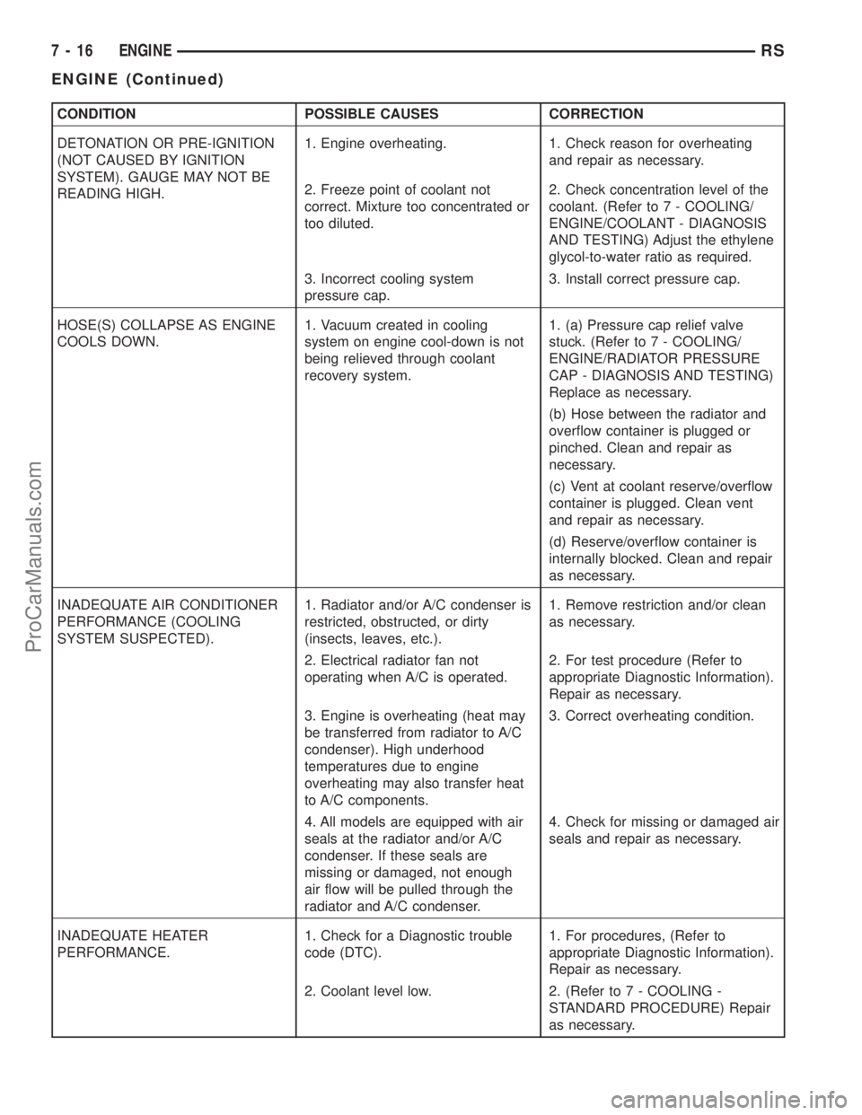
CONDITION POSSIBLE CAUSES CORRECTION
DETONATION OR PRE-IGNITION
(NOT CAUSED BY IGNITION
SYSTEM). GAUGE MAY NOT BE
READING HIGH.1. Engine overheating. 1. Check reason for overheating
and repair as necessary.
2. Freeze point of coolant not
correct. Mixture too concentrated or
too diluted.2. Check concentration level of the
coolant. (Refer to 7 - COOLING/
ENGINE/COOLANT - DIAGNOSIS
AND TESTING) Adjust the ethylene
glycol-to-water ratio as required.
3. Incorrect cooling system
pressure cap.3. Install correct pressure cap.
HOSE(S) COLLAPSE AS ENGINE
COOLS DOWN.1. Vacuum created in cooling
system on engine cool-down is not
being relieved through coolant
recovery system.1. (a) Pressure cap relief valve
stuck. (Refer to 7 - COOLING/
ENGINE/RADIATOR PRESSURE
CAP - DIAGNOSIS AND TESTING)
Replace as necessary.
(b) Hose between the radiator and
overflow container is plugged or
pinched. Clean and repair as
necessary.
(c) Vent at coolant reserve/overflow
container is plugged. Clean vent
and repair as necessary.
(d) Reserve/overflow container is
internally blocked. Clean and repair
as necessary.
INADEQUATE AIR CONDITIONER
PERFORMANCE (COOLING
SYSTEM SUSPECTED).1. Radiator and/or A/C condenser is
restricted, obstructed, or dirty
(insects, leaves, etc.).1. Remove restriction and/or clean
as necessary.
2. Electrical radiator fan not
operating when A/C is operated.2. For test procedure (Refer to
appropriate Diagnostic Information).
Repair as necessary.
3. Engine is overheating (heat may
be transferred from radiator to A/C
condenser). High underhood
temperatures due to engine
overheating may also transfer heat
to A/C components.3. Correct overheating condition.
4. All models are equipped with air
seals at the radiator and/or A/C
condenser. If these seals are
missing or damaged, not enough
air flow will be pulled through the
radiator and A/C condenser.4. Check for missing or damaged air
seals and repair as necessary.
INADEQUATE HEATER
PERFORMANCE.1. Check for a Diagnostic trouble
code (DTC).1. For procedures, (Refer to
appropriate Diagnostic Information).
Repair as necessary.
2. Coolant level low. 2. (Refer to 7 - COOLING -
STANDARD PROCEDURE) Repair
as necessary.
7 - 16 ENGINERS
ENGINE (Continued)
ProCarManuals.com
Page 266 of 2399
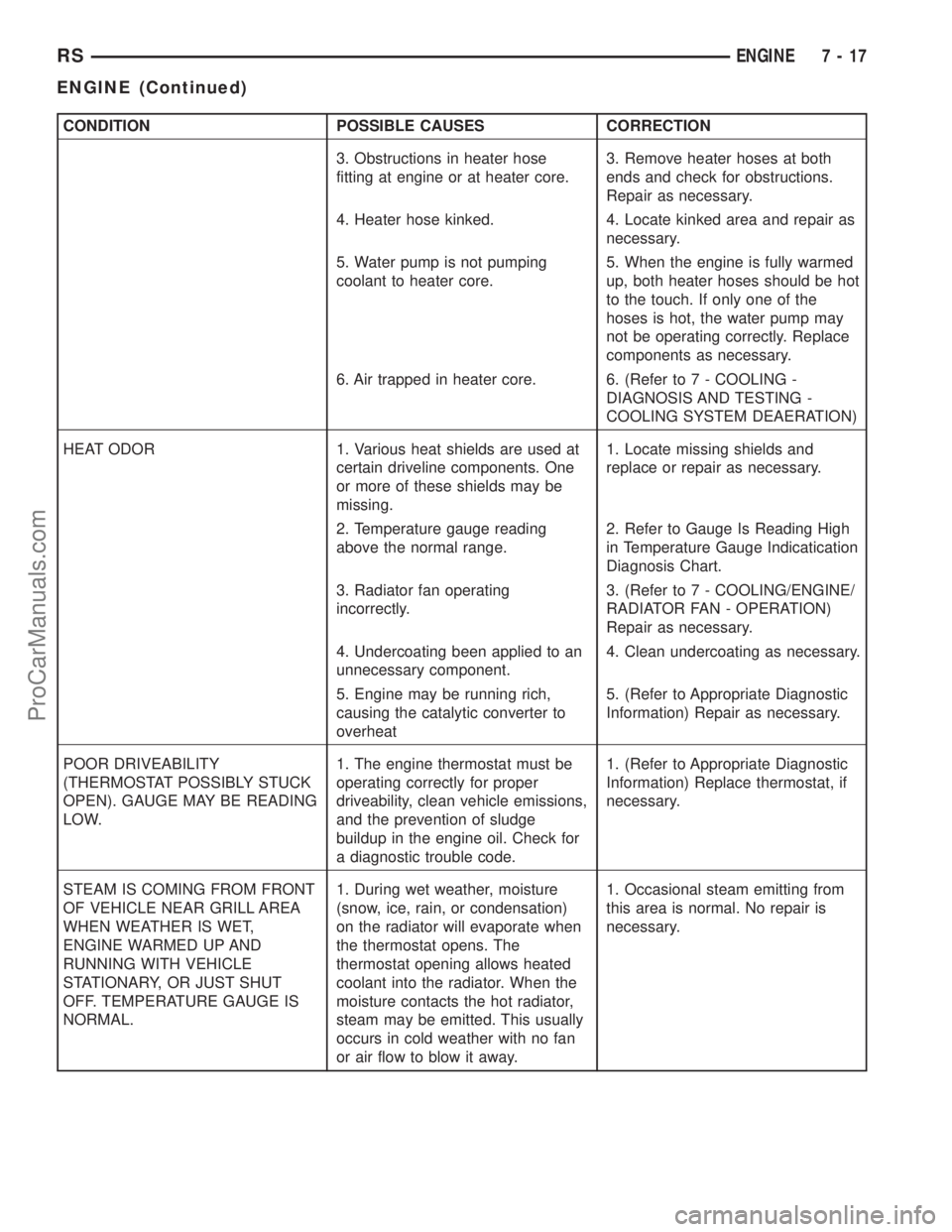
CONDITION POSSIBLE CAUSES CORRECTION
3. Obstructions in heater hose
fitting at engine or at heater core.3. Remove heater hoses at both
ends and check for obstructions.
Repair as necessary.
4. Heater hose kinked. 4. Locate kinked area and repair as
necessary.
5. Water pump is not pumping
coolant to heater core.5. When the engine is fully warmed
up, both heater hoses should be hot
to the touch. If only one of the
hoses is hot, the water pump may
not be operating correctly. Replace
components as necessary.
6. Air trapped in heater core. 6. (Refer to 7 - COOLING -
DIAGNOSIS AND TESTING -
COOLING SYSTEM DEAERATION)
HEAT ODOR 1. Various heat shields are used at
certain driveline components. One
or more of these shields may be
missing.1. Locate missing shields and
replace or repair as necessary.
2. Temperature gauge reading
above the normal range.2. Refer to Gauge Is Reading High
in Temperature Gauge Indicatication
Diagnosis Chart.
3. Radiator fan operating
incorrectly.3. (Refer to 7 - COOLING/ENGINE/
RADIATOR FAN - OPERATION)
Repair as necessary.
4. Undercoating been applied to an
unnecessary component.4. Clean undercoating as necessary.
5. Engine may be running rich,
causing the catalytic converter to
overheat5. (Refer to Appropriate Diagnostic
Information) Repair as necessary.
POOR DRIVEABILITY
(THERMOSTAT POSSIBLY STUCK
OPEN). GAUGE MAY BE READING
LOW.1. The engine thermostat must be
operating correctly for proper
driveability, clean vehicle emissions,
and the prevention of sludge
buildup in the engine oil. Check for
a diagnostic trouble code.1. (Refer to Appropriate Diagnostic
Information) Replace thermostat, if
necessary.
STEAM IS COMING FROM FRONT
OF VEHICLE NEAR GRILL AREA
WHEN WEATHER IS WET,
ENGINE WARMED UP AND
RUNNING WITH VEHICLE
STATIONARY, OR JUST SHUT
OFF. TEMPERATURE GAUGE IS
NORMAL.1. During wet weather, moisture
(snow, ice, rain, or condensation)
on the radiator will evaporate when
the thermostat opens. The
thermostat opening allows heated
coolant into the radiator. When the
moisture contacts the hot radiator,
steam may be emitted. This usually
occurs in cold weather with no fan
or air flow to blow it away.1. Occasional steam emitting from
this area is normal. No repair is
necessary.
RSENGINE7-17
ENGINE (Continued)
ProCarManuals.com
Page 267 of 2399

CONDITION POSSIBLE CAUSES CORRECTION
COOLANT COLOR 1. Coolant color is not necessarily
an indication of adequate corrosion
or temperature protection. Do not
rely on coolant color for determining
condition of coolant.1. Check the freeze point of the
coolant. (Refer to 7 - COOLING/
ENGINE/COOLANT - DIAGNOSIS
AND TESTING) Adjust the ethylene
glycol-to-water ratio as necessary.
COOLANT LEVEL CHANGES IN
COOLANT BOTTLE.
TEMPERATURE GAUGE IS IN
NORMAL RANGE.1. Level changes are to be
expected as coolant volume
fluctuates with engine temperature.
The coolant level will also drop as
the system removes air from a
recent filling.1. A normal condition. No repair is
necessary.
Refer to (Fig. 1) when using the TEMPERATURE
GAUGE INDICATION DIAGNOSIS CHART.
TEMPERATURE GAUGE INDICATION DIAGNOSIS CHART
CONDITION POSSIBLE CAUSES CORRECTION
TEMPERATURE GAUGE READING
IS INCONSISTENT (FLUCTUATES,
CYCLES OR IS ERRATIC).1. Normal reaction to fan and/or
thermostat cycle (Fig. 1 ),
Examples B and C. During cold
weather operation with the heater
blower in the high position, the
gauge reading may drop slightly
(Fig. 1 ), Example D. Fluctuation is
also influenced by outside
temperature and heavy loads (Fig.
1 ), Example E.1. A normal condition. No correction
is necessary.
2. Gauge reading rises when
vehicle is brought to a stop after
heavy use (engine still running)
(Fig. 1 ), Example F.2. A normal condition. No correction
is necessary. Gauge reading should
return to normal range (Fig. 1 ),
Example A, after vehicle is driven.
3. Gauge reading high after
restarting a warmed-up (hot)
engine.3. A normal condition. No correction
is necessary. The gauge should
return to normal range (Fig. 1 ),
Example A, after a few minutes of
engine operation.
4. Temperature gauge or engine
coolant temperature sensor
defective or shorted. Also, corroded
or loose wiring in the electrical
circuit.4. Check operation of gauge or
engine coolant temperature sensor
and repair, if necessary.
7 - 18 ENGINERS
ENGINE (Continued)
ProCarManuals.com
Page 268 of 2399

CLEANING
Drain cooling system and refill with clean water.
Refer to drain and fill procedures in this section. Run
engine with radiator cap installed until upper radia-
tor hose is hot. Stop engine and drain water from
system. If water is dirty; fill, run, and drain system
again, until water runs clear. Refill cooling system
with a 50/50 mixture of the recommended ethylene
glycol and distilled water (Refer to LUBRICATION &
MAINTENANCE/FLUID TYPES - DESCRIPTION).
INSPECTION
After performing a cleaning/flush procedure,
inspect all hoses, clamps and connections for deterio-
ration and leaks. Inspect radiator and heater core for
leaks.
COOLANT
DIAGNOSIS AND TESTING - COOLANT
CONCENTRATION TESTING
Coolant concentration should be checked when any
additional coolant was added to system or after a
coolant drain, flush and refill. The coolant mixture
offers optimum engine cooling and protection against
corrosion when mixed to a freeze point of -37ÉC
(-34ÉF) to -46ÉC (-50ÉF). The use of a hydrometer or a
refractometer can be used to test coolant concentra-
tion.
A hydrometer will test the amount of glycol in a
mixture by measuring the specific gravity of the mix-
ture. The higher the concentration of ethylene glycol,
the larger the number of balls that will float, and
Fig. 1 Temperature Gauge Indications
RSENGINE7-19
ENGINE (Continued)
ProCarManuals.com
Page 269 of 2399
higher the freeze protection (up to a maximum of
60% by volume glycol).
A refractometer (Special Tool 8286)(Refer to 7 -
COOLING - SPECIAL TOOLS) will test the amount
of glycol in a coolant mixture by measuring the
amount a beam of light bends as it passes through
the fluid.
Some coolant manufactures use other types of gly-
cols into their coolant formulations. Propylene glycol
is the most common new coolant. However, propylene
glycol based coolants do not provide the same freez-
ing protection and corrosion protection and is not rec-
ommended.
CAUTION: Do not mix types of coolantÐcorrosion
protection will be severely reduced.
STANDARD PROCEDURE - COOLANT SERVICE
For engine coolant recommended service schedule,
(Refer to LUBRICATION & MAINTENANCE/MAIN-
TENANCE SCHEDULES - DESCRIPTION).
COOLANT RECOVERY
CONTAINER
DESCRIPTION
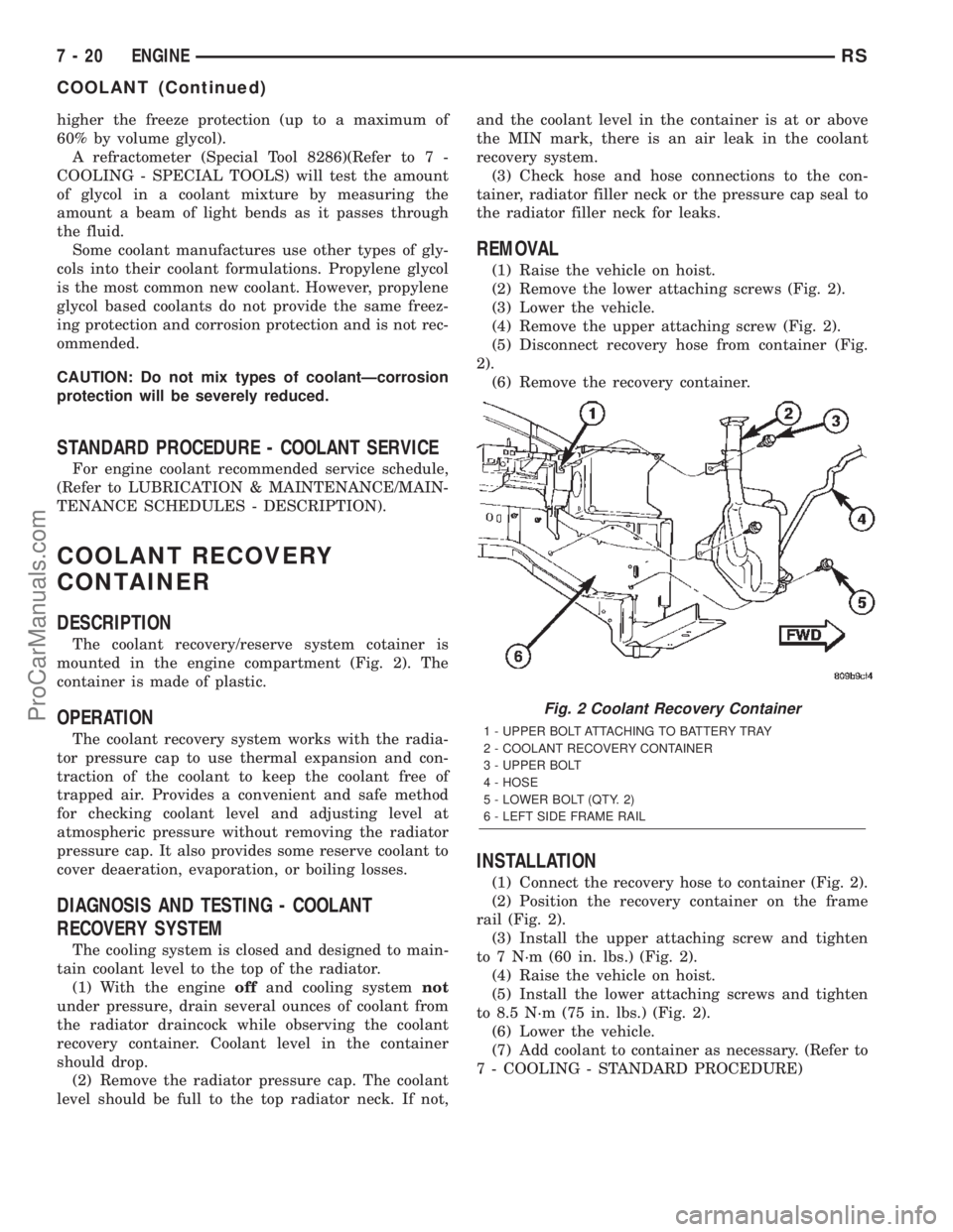
The coolant recovery/reserve system cotainer is
mounted in the engine compartment (Fig. 2). The
container is made of plastic.
OPERATION
The coolant recovery system works with the radia-
tor pressure cap to use thermal expansion and con-
traction of the coolant to keep the coolant free of
trapped air. Provides a convenient and safe method
for checking coolant level and adjusting level at
atmospheric pressure without removing the radiator
pressure cap. It also provides some reserve coolant to
cover deaeration, evaporation, or boiling losses.
DIAGNOSIS AND TESTING - COOLANT
RECOVERY SYSTEM
The cooling system is closed and designed to main-
tain coolant level to the top of the radiator.
(1) With the engineoffand cooling systemnot
under pressure, drain several ounces of coolant from
the radiator draincock while observing the coolant
recovery container. Coolant level in the container
should drop.
(2) Remove the radiator pressure cap. The coolant
level should be full to the top radiator neck. If not,and the coolant level in the container is at or above
the MIN mark, there is an air leak in the coolant
recovery system.
(3) Check hose and hose connections to the con-
tainer, radiator filler neck or the pressure cap seal to
the radiator filler neck for leaks.
REMOVAL
(1) Raise the vehicle on hoist.
(2) Remove the lower attaching screws (Fig. 2).
(3) Lower the vehicle.
(4) Remove the upper attaching screw (Fig. 2).
(5) Disconnect recovery hose from container (Fig.
2).
(6) Remove the recovery container.
INSTALLATION
(1) Connect the recovery hose to container (Fig. 2).
(2) Position the recovery container on the frame
rail (Fig. 2).
(3) Install the upper attaching screw and tighten
to 7 N´m (60 in. lbs.) (Fig. 2).
(4) Raise the vehicle on hoist.
(5) Install the lower attaching screws and tighten
to 8.5 N´m (75 in. lbs.) (Fig. 2).
(6) Lower the vehicle.
(7) Add coolant to container as necessary. (Refer to
7 - COOLING - STANDARD PROCEDURE)
Fig. 2 Coolant Recovery Container
1 - UPPER BOLT ATTACHING TO BATTERY TRAY
2 - COOLANT RECOVERY CONTAINER
3 - UPPER BOLT
4 - HOSE
5 - LOWER BOLT (QTY. 2)
6 - LEFT SIDE FRAME RAIL
7 - 20 ENGINERS
COOLANT (Continued)
ProCarManuals.com
Page 270 of 2399
ENGINE BLOCK HEATER
DESCRIPTION
The engine block heater is available as an optional
accessory on all models. The heater is operated by
ordinary house current (110 Volt A.C.) through a
power cord located behind the radiator grille. This
provides easier engine starting and faster warm-up
when vehicle is operated in areas having extremely
low temperatures. The heater is mounted in a core
hole (in place of a core hole plug) in the engine block,
with the heating element immersed in coolant.
OPERATION
The block heater element is submerged in the cool-
ing system's coolant. When electrical power (110 volt
A.C.) is applied to the element, it creates heat. This
heat is transferred to the engine coolant. This pro-
vides easier engine starting and faster warm-up
when vehicle is operated in areas having extremely
low temperatures.
DIAGNOSIS AND TESTING - ENGINE BLOCK
HEATER TESTING
If unit does not operate, trouble can be in either
the power cord or the heater element. Test power
cord for continuity with a 110-volt voltmeter or 110-
volt test light; test heater element continuity with an
ohmmeter or 12-volt test light.
REMOVAL
(1) Drain coolant from radiator and cylinder block.
(Refer to 7 - COOLING - STANDARD PROCEDURE)
(2) Disconnect the power cord plug from heater.
(3) Loosen screw in center of heater. Remove the
heater assembly.
INSTALLATION
(1) Clean block core hole and heater seat.
(2) Insert heater assembly with element loop posi-
tionedupward.
(3) With heater seated, tighten center screw
securely to assure a positive seal.
(4) Install power cord plug to heater.
(5) Fill cooling system with coolant to the proper
level. (Refer to 7 - COOLING - STANDARD PROCE-
DURE)
ENGINE COOLANT
TEMPERATURE SENSOR - 2.4L
DESCRIPTION
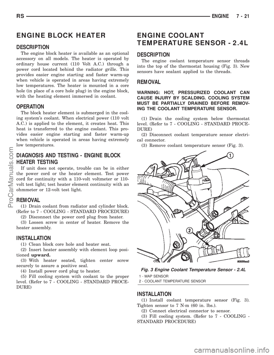
The engine coolant temperature sensor threads
into the top of the thermostat housing (Fig. 3). New
sensors have sealant applied to the threads.
REMOVAL
WARNING: HOT, PRESSURIZED COOLANT CAN
CAUSE INJURY BY SCALDING. COOLING SYSTEM
MUST BE PARTIALLY DRAINED BEFORE REMOV-
ING THE COOLANT TEMPERATURE SENSOR.
(1) Drain the cooling system below thermostat
level. (Refer to 7 - COOLING - STANDARD PROCE-
DURE)
(2) Disconnect coolant temperature sensor electri-
cal connector.
(3) Remove coolant temperature sensor (Fig. 3).
INSTALLATION
(1) Install coolant temperature sensor (Fig. 3).
Tighten sensor to 7 N´m (60 in. lbs.).
(2) Connect electrical connector to sensor.
(3) Fill cooling system. (Refer to 7 - COOLING -
STANDARD PROCEDURE)
Fig. 3 Engine Coolant Temperature Sensor - 2.4L
1 - MAP SENSOR
2 - COOLANT TEMPERATURE SENSOR
RSENGINE7-21
ProCarManuals.com