compressor CHRYSLER VOYAGER 2002 Owner's Manual
[x] Cancel search | Manufacturer: CHRYSLER, Model Year: 2002, Model line: VOYAGER, Model: CHRYSLER VOYAGER 2002Pages: 2399, PDF Size: 57.96 MB
Page 1037 of 2399
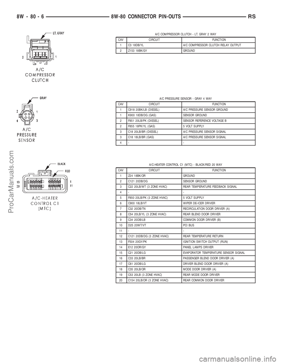
A/C COMPRESSOR CLUTCH - LT. GRAY 2 WAY
CAV CIRCUIT FUNCTION
1 C3 18DB/YL A/C COMPRESSOR CLUTCH RELAY OUTPUT
2 Z153 18BK/GY GROUND
A/C PRESSURE SENSOR - GRAY 4 WAY
CAV CIRCUIT FUNCTION
1 C918 20BK/LB (DIESEL) A/C PRESSURE SENSOR GROUND
1 K900 18DB/DG (GAS) SENSOR GROUND
2 F851 20LB/PK (DIESEL) SENSOR REFERENCE VOLTAGE B
2 F855 18PK/YL (GAS) 5 VOLT SUPPLY
3 C18 20LB/BR (DIESEL) A/C PRESSURE SENSOR SIGNAL
3 C18 18LB/BR (GAS) A/C PRESSURE SENSOR SIGNAL
4- -
A/C-HEATER CONTROL C1 (MTC) - BLACK/RED 20 WAY
CAV CIRCUIT FUNCTION
1 Z24 18BK/OR GROUND
2 C121 20DB/DG SENSOR GROUND
3 C22 20LB/WT (3 ZONE HVAC) REAR TEMPERATURE FEEDBACK SIGNAL
4- -
5 F850 20LB/PK (3 ZONE HVAC) 5 VOLT SUPPLY
6 C900 18LB/VT WIPER DE-ICER DRIVER
7 C32 20DB/TN RECIRCULATION DOOR DRIVER (A)
8 C54 20LB/YL (3 ZONE HVAC) REAR BLEND DOOR DRIVER
9 C34 20DB/LB COMMON DOOR DRIVER (B)
10 D25 20WT/VT PCI BUS
11 - -
12 C121 20DB/DG (3 ZONE HVAC) REAR TEMPERATURE RETURN
13 F504 20GY/PK IGNITION SWITCH OUTPUT (RUN)
14 E12 20OR/GY PANEL LAMPS DRIVER
15 C21 20DB/LG EVAPORATOR TEMPERATURE SENSOR SIGNAL
16 C33 20LB/BR PASSENGER BLEND DOOR DRIVER (A)
17 C61 20DB/LG DRIVER BLEND DOOR DRIVER (A)
18 C35 20LB/OR MODE DOOR DRIVER (A)
19 C53 20LB (3 ZONE HVAC) REAR MODE DOOR DRIVER
20 C154 20LB/OR (3 ZONE HVAC) REAR COMMON DOOR DRIVER
8W - 80 - 6 8W-80 CONNECTOR PIN-OUTSRS
ProCarManuals.com
Page 1087 of 2399

ENGINE CONTROL MODULE C1 (DIESEL) - BLACK 81 WAY
CAV CIRCUIT FUNCTION
55 N7 20DB/OR VEHICLE SPEED SENSOR SIGNAL
56 C918 20BK/LB A/C PRESSURE SENSOR GROUND
57 - -
58 K4 20BK/LB LOW IDLE POSITION SWITCH GROUND
59 - -
60 K9 20LB FUEL PRESSURE SENSOR 5 VOLT SUPPLY
61 K51 20BR/WT ECM/PCM RELAY CONTROL
62 - -
63 D21 20WT/BR SCI TRANSMIT
64 K151 20WT LOW IDLE POSITION SWITCH SENSE
65 - -
66 K936 20BR/YL ENGINE OIL PRESSURE SENSOR GROUND
67 - -
68 - -
69 C13 20LB/OR A/C COMPRESSOR CLUTCH RELAY CONTROL
70 N210 20DB/DG LOW SPEED RADIATOR FAN RELAY CONTROL
71 - -
72 N21 20DB/TN LIFT PUMP RELAY CONTROL
73 - -
74 T752 20DG/OR ENGINE STARTER MOTOR RELAY CONTROL
75 - -
76 - -
77 K152 20DB/WT GLOW PLUG RELAY CONTROL
78 N122 20DB/YL HIGH SPEED RADIATOR FAN DUAL RELAY CONTROL
79 - -
80 K87 20BR FUEL PRESSURE SOLENOID CONTROL
81 K87 20BR FUEL PRESSURE SOLENOID CONTROL
8W - 80 - 56 8W-80 CONNECTOR PIN-OUTSRS
ProCarManuals.com
Page 1099 of 2399

INTEGRATED POWER MODULE C3 (DIESEL) - YELLOW/RED 20 WAY
CAV CIRCUIT FUNCTION
1 N21 20DB/TN LIFT PUMP RELAY CONTROL
2- -
3 T751 20YL FUSED IGNITION SWITCH OUTPUT (START)
4 T2 18DG/WT TRS REVERSE SENSE
5 N2 18DB/YL LIFT PUMP RELAY OUTPUT
6 F202 18PK/GY FUSED IGNITION SWITCH OUTPUT (RUN-START)
7 C3 18DB/YL A/C COMPRESSOR CLUTCH RELAY OUTPUT
8 Z114 18BK/LG GROUND
9 C13 20LB/OR A/C COMPRESSOR CLUTCH RELAY CONTROL
10 A119 16RD/OR FUSED B(+)
11 C41 20LB/DG CABIN HEATER ASSIST CONTROL
12 T753 20DG/YL FUSED IGNITION SWITCH OUTPUT (START)
13 - -
14 T752 20DG/OR ENGINE STARTER MOTOR RELAY CONTROL
15 Z116 18BK/VT GROUND
16 K51 20BR/WT ECM/PCM RELAY CONTROL
17 F202 18PK/GY FUSED IGNITION SWITCH OUTPUT (RUN-START)
18 - -
19 K342 16BR/WT ECM/PCM RELAY OUTPUT
20 - -
INTEGRATED POWER MODULE C3 (GAS) - NATURAL/RED 20 WAY
CAV CIRCUIT FUNCTION
1 Z115 20BK/OR (EATX) (3.3L/3.8L) GROUND
1 Z115 18BK/OR (EATX) (2.4L) GROUND
2 F1 18PK/WT (EATX) FCM OUTPUT (UNLOCK-RUN-START)
3 T751 18YL (EATX) FUSED IGNITION SWITCH OUTPUT (START)
4 T2 18DG/WT TRS REVERSE SENSE
5 T16 18YL/OR (EATX) TRANSMISSION CONTROL RELAY OUTPUT
6 T15 18YL/BR (EATX) TRANSMISSION CONTROL RELAY CONTROL
7 C3 18DB/YL A/C COMPRESSOR CLUTCH RELAY OUTPUT
8 K31 18BR FUEL PUMP RELAY CONTROL
9 C13 18LB/OR A/C COMPRESSOR CLUTCH RELAY CONTROL
10 A104 18YL/RD (EATX) FUSED B(+)
11 - -
12 - -
13 D25 18WT/VT (EATX) PCI BUS (EATX)
14 T752 18DG/OR ENGINE STARTER MOTOR RELAY CONTROL
15 Z116 18BK/VT GROUND
16 K51 18BR/WT AUTOMATIC SHUT DOWN RELAY CONTROL
17 F202 18PK/GY FUSED IGNITION SWITCH OUTPUT (RUN-START)
18 K173 18BR/VT RADIATOR FAN RELAY CONTROL
19 F202 18PK/GY FUSED IGNITION SWITCH OUTPUT (RUN-START)
20 A109 18OR/RD FUSED B(+)
8W - 80 - 68 8W-80 CONNECTOR PIN-OUTSRS
ProCarManuals.com
Page 1126 of 2399

POWERTRAIN CONTROL MODULE C2 (GAS) - GRAY/GRAY 40 WAY
CAV CIRCUIT FUNCTION
41 V37 18VT SPEED CONTROL SWITCH SIGNAL
42 C18 18LB/BR A/C PRESSURE SENSOR SIGNAL
43 K900 18DB/DG SENSOR GROUND
44 F888 18BR/PK 8 VOLT SUPPLY
45 - -
46 A109 18OR/RD FUSED B(+)
47 - -
48 K40 18BR/LG (2.4L) IDLE AIR CONTROL NO. 3 DRIVER
49 K60 18VT/LG (2.4L) IDLE AIR CONTROL NO. 2 DRIVER
49 K39 18VT/DG (3.3L/3.8L) IDLE AIR CONTROL NO. 1 DRIVER
50 Z131 18BK/DG GROUND
51 K141 18DB/YL OXYGEN SENSOR 1/2 SIGNAL
52 - -
53 - -
54 - -
55 - -
56 V36 18VT/YL SPEED CONTROL VACUUM SOLENOID CONTROL
57 K39 18VT/DG (2.4L) IDLE AIR CONTROL NO. 1 DRIVER
57 K60 18VT/LG (3.3L/3.8L) IDLE AIR CONTROL NO. 2 DRIVER
58 K59 18BR/DG (2.4L) IDLE AIR CONTROL NO. 4 DRIVER
59 D25 18WT/VT PCI BUS
60 - -
61 F855 18PK/YL 5 VOLT SUPPLY
62 B29 18DG/WT SECONDARY BRAKE SWITCH SIGNAL
63 T10 18DG/LG (EATX) TORQUE MANAGEMENT REQUEST SENSE
64 C13 18LB/OR A/C COMPRESSOR CLUTCH RELAY CONTROL
65 D21 18WT/BR SCI TRANSMIT
66 N7 18DB/OR VEHICLE SPEED SENSOR SIGNAL
67 K51 18BR/WT AUTOMATIC SHUT DOWN RELAY CONTROL
68 K52 18DB/WT EVAPORATIVE EMISSION SOLENOID CONTROL
69 - -
70 K70 18DB/BR EVAPORATIVE EMISSION SOLENOID SENSE
71 - -
72 K107 18VT/WT (EXCEPT
BUILT-UP-EXPORT)LEAK DETECTION PUMP SWITCH SENSE
73 K173 18BR/VT RADIATOR FAN RELAY CONTROL
74 K31 18BR FUEL PUMP RELAY CONTROL
75 D20 18WT/LG SCI RECEIVE
76 T41 18YL/DB PARK/NEUTRAL POSITION SWITCH SENSE (TRS T41)
77 K106 18VT/WT (EXCEPT
BUILT-UP-EXPORT) (2.4L EATX W/ABS)LEAK DETECTION PUMP SOLENOID CONTROL
77 K106 18VT/LB (EXCEPT
BUILT-UP-EXPORT) (EXCEPT 2.4L EATX
W/ABS)LEAK DETECTION PUMP SOLENOID CONTROL
78 K54 18DB/WT (ATX) TORQUE CONVERTER CLUTCH SOLENOID CONTROL
79 - -
80 V35 18VT/OR SPEED CONTROL VENT SOLENOID CONTROL
RS8W-80 CONNECTOR PIN-OUTS8W-80-95
ProCarManuals.com
Page 1148 of 2399

8W-91 CONNECTOR/GROUND/SPLICE LOCATION
TABLE OF CONTENTS
page
CONNECTOR/GROUND/SPLICE LOCATION
DESCRIPTION..........................1
CONNECTOR/GROUND/SPLICE
LOCATION
DESCRIPTION
This section provides illustrations identifying con-
nector, ground, and splice locations in the vehicle.Connector, ground, and splice indexes are provided.
Use the wiring diagrams in each section for connec-
tor, ground, and splice identification. Refer to the
appropriate index for the proper figure number. For
items that are not shown in this section N/S is placed
in the Fig. column.
CONNECTORS
CONNECTOR NAME/NUMBER COLOR LOCATION FIG.
A/C Compressor Clutch LTGY Top of A/C Compressor 9, 10, 11, 13, 14
A/C-Heater Control C1 (MTC) BK/RD Rear of Control 15, 18, 20
A/C-Heater Control C2 (MTC) BK/BL Rear of Control 15, 18, 20
A/C Pressure Transducer GY At Throttle Body 9, 11, 12, 13
Accelerator Pedal Position Sensor
(Diesel)BK At Accelerator Pedal 36
Airbag Control Module YL/RD Right Side of Instrument Panel 15, 19, 20
Ambient Temperature Sensor BK On Radiator Closure Panel 1
ATC Remote Sensor Above ATC Control N/S
Automatic Day/Night Mirror BK At Mirror N/S
Autostick Switch BK Rear of Switch 16, 17, 18
Auto Temperature Control C1
(ATC)WT Rear of Control N/S
Auto Temperature Control C2
(ATC)BK Rear of Control N/S
Auto Temperature Control C3
(ATC)Rear of Control N/S
Back-Up Lamp Switch BK On Transmission 12
Battery Temperature Sensor
(Diesel)BK At Battery N/S
Blower Motor Resistor C1 (MTC) BK Right Side of HVAC N/S
Blower Motor Resistor C2 (MTC) Right Side of HVAC N/S
Body Control Module C1 BK Under Left Instrument Panel 35, 36
Body Control Module C2 BK/GN Under Left Instrument Panel 35, 36
Body Control Module C3 BK/WT Under Left Instrument Panel 35, 36
Body Control Module C4 BK/GY Under Left Instrument Panel 15, 16, 25
Body Control Module C5 BK Under Left Instrument Panel 15, 16, 25
RS8W-91 CONNECTOR/GROUND/SPLICE LOCATION8W-91-1
ProCarManuals.com
Page 1159 of 2399
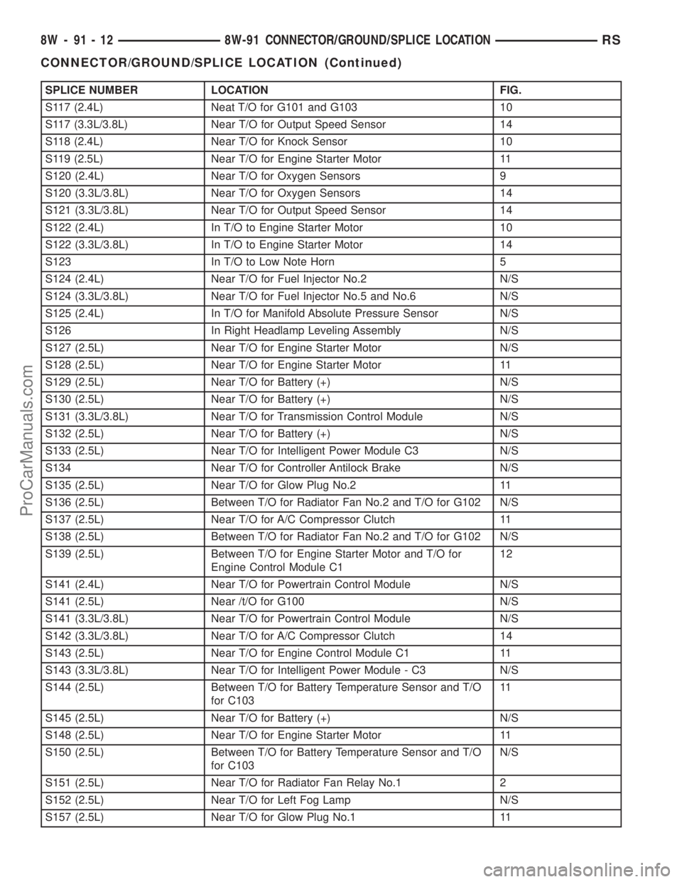
SPLICE NUMBER LOCATION FIG.
S117 (2.4L) Neat T/O for G101 and G103 10
S117 (3.3L/3.8L) Near T/O for Output Speed Sensor 14
S118 (2.4L) Near T/O for Knock Sensor 10
S119 (2.5L) Near T/O for Engine Starter Motor 11
S120 (2.4L) Near T/O for Oxygen Sensors 9
S120 (3.3L/3.8L) Near T/O for Oxygen Sensors 14
S121 (3.3L/3.8L) Near T/O for Output Speed Sensor 14
S122 (2.4L) In T/O to Engine Starter Motor 10
S122 (3.3L/3.8L) In T/O to Engine Starter Motor 14
S123 In T/O to Low Note Horn 5
S124 (2.4L) Near T/O for Fuel Injector No.2 N/S
S124 (3.3L/3.8L) Near T/O for Fuel Injector No.5 and No.6 N/S
S125 (2.4L) In T/O for Manifold Absolute Pressure Sensor N/S
S126 In Right Headlamp Leveling Assembly N/S
S127 (2.5L) Near T/O for Engine Starter Motor N/S
S128 (2.5L) Near T/O for Engine Starter Motor 11
S129 (2.5L) Near T/O for Battery (+) N/S
S130 (2.5L) Near T/O for Battery (+) N/S
S131 (3.3L/3.8L) Near T/O for Transmission Control Module N/S
S132 (2.5L) Near T/O for Battery (+) N/S
S133 (2.5L) Near T/O for Intelligent Power Module C3 N/S
S134 Near T/O for Controller Antilock Brake N/S
S135 (2.5L) Near T/O for Glow Plug No.2 11
S136 (2.5L) Between T/O for Radiator Fan No.2 and T/O for G102 N/S
S137 (2.5L) Near T/O for A/C Compressor Clutch 11
S138 (2.5L) Between T/O for Radiator Fan No.2 and T/O for G102 N/S
S139 (2.5L) Between T/O for Engine Starter Motor and T/O for
Engine Control Module C112
S141 (2.4L) Near T/O for Powertrain Control Module N/S
S141 (2.5L) Near /t/O for G100 N/S
S141 (3.3L/3.8L) Near T/O for Powertrain Control Module N/S
S142 (3.3L/3.8L) Near T/O for A/C Compressor Clutch 14
S143 (2.5L) Near T/O for Engine Control Module C1 11
S143 (3.3L/3.8L) Near T/O for Intelligent Power Module - C3 N/S
S144 (2.5L) Between T/O for Battery Temperature Sensor and T/O
for C10311
S145 (2.5L) Near T/O for Battery (+) N/S
S148 (2.5L) Near T/O for Engine Starter Motor 11
S150 (2.5L) Between T/O for Battery Temperature Sensor and T/O
for C103N/S
S151 (2.5L) Near T/O for Radiator Fan Relay No.1 2
S152 (2.5L) Near T/O for Left Fog Lamp N/S
S157 (2.5L) Near T/O for Glow Plug No.1 11
8W - 91 - 12 8W-91 CONNECTOR/GROUND/SPLICE LOCATIONRS
CONNECTOR/GROUND/SPLICE LOCATION (Continued)
ProCarManuals.com
Page 1215 of 2399
(22) Remove engine front mount and bracket from
engine. (Refer to 9 - ENGINE/ENGINE MOUNTING/
FRONT MOUNT - REMOVAL)
(23) Remove structural collar. (Refer to 9 -
ENGINE/ENGINE BLOCK/STRUCTURAL COVER -
REMOVAL)
(24) Remove rear engine mount bracket. (Refer to
9 - ENGINE/ENGINE MOUNTING/REAR MOUNT -
REMOVAL)
(25) Mark flex plate to torque converter and
remove torque converter bolts.
(26) Pinch-off power steering supply hose at pump.
Remove hose from pump.
(27) Remove and set aside the power steering
pump and bracket. Do not disconnect pressure line.
(28) Lower vehicle.
(29) Remove A/C lines at compressor and cap open-
ings.
(30) Remove engine ground straps (strap at engine
right mount and at starter).
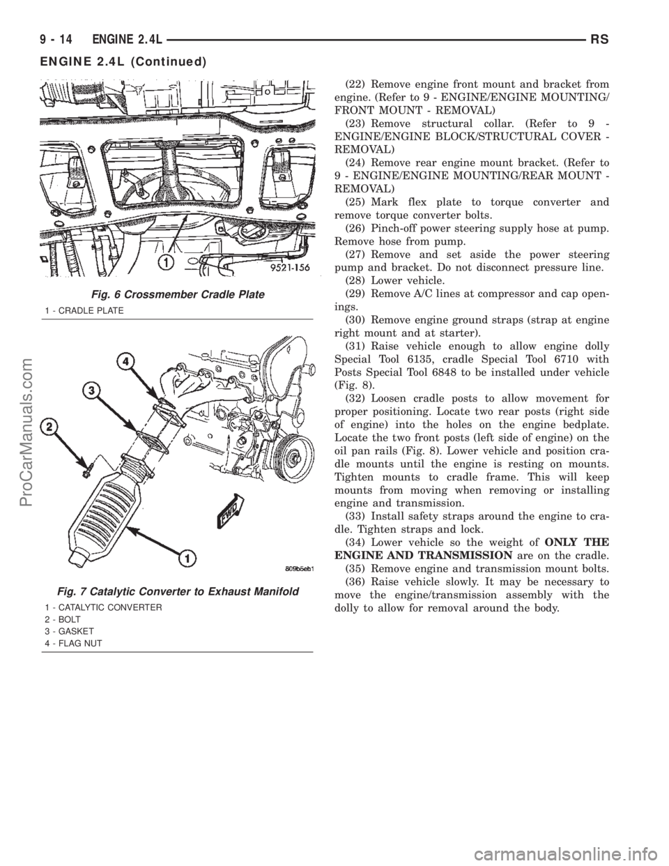
(31) Raise vehicle enough to allow engine dolly
Special Tool 6135, cradle Special Tool 6710 with
Posts Special Tool 6848 to be installed under vehicle
(Fig. 8).
(32) Loosen cradle posts to allow movement for
proper positioning. Locate two rear posts (right side
of engine) into the holes on the engine bedplate.
Locate the two front posts (left side of engine) on the
oil pan rails (Fig. 8). Lower vehicle and position cra-
dle mounts until the engine is resting on mounts.
Tighten mounts to cradle frame. This will keep
mounts from moving when removing or installing
engine and transmission.
(33) Install safety straps around the engine to cra-
dle. Tighten straps and lock.
(34) Lower vehicle so the weight ofONLY THE
ENGINE AND TRANSMISSIONare on the cradle.
(35) Remove engine and transmission mount bolts.
(36) Raise vehicle slowly. It may be necessary to
move the engine/transmission assembly with the
dolly to allow for removal around the body.
Fig. 6 Crossmember Cradle Plate
1 - CRADLE PLATE
Fig. 7 Catalytic Converter to Exhaust Manifold
1 - CATALYTIC CONVERTER
2 - BOLT
3 - GASKET
4 - FLAG NUT
9 - 14 ENGINE 2.4LRS
ENGINE 2.4L (Continued)
ProCarManuals.com
Page 1217 of 2399
INSTALLATION - ENGINE ASSEMBLY
(1) Position engine and transmission assembly
under vehicle and slowly lower the vehicle over the
engine and transmission.
(2) Align engine and transmission mounts to
attaching points. Install mounting bolts at the right
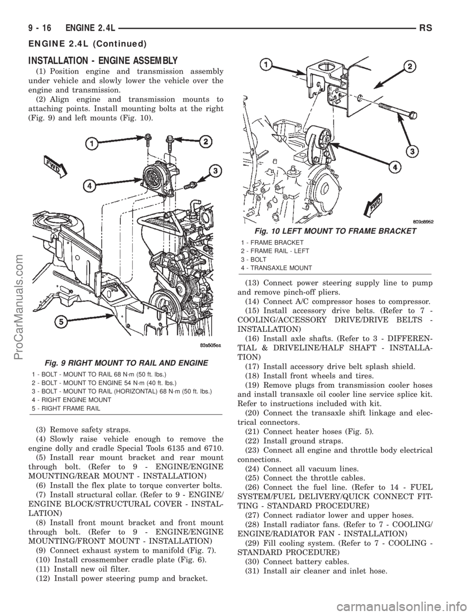
(Fig. 9) and left mounts (Fig. 10).
(3) Remove safety straps.
(4) Slowly raise vehicle enough to remove the
engine dolly and cradle Special Tools 6135 and 6710.
(5) Install rear mount bracket and rear mount
through bolt. (Refer to 9 - ENGINE/ENGINE
MOUNTING/REAR MOUNT - INSTALLATION)
(6) Install the flex plate to torque converter bolts.
(7) Install structural collar. (Refer to 9 - ENGINE/
ENGINE BLOCK/STRUCTURAL COVER - INSTAL-
LATION)
(8) Install front mount bracket and front mount
through bolt. (Refer to 9 - ENGINE/ENGINE
MOUNTING/FRONT MOUNT - INSTALLATION)
(9) Connect exhaust system to manifold (Fig. 7).
(10) Install crossmember cradle plate (Fig. 6).
(11) Install new oil filter.
(12) Install power steering pump and bracket.(13) Connect power steering supply line to pump
and remove pinch-off pliers.
(14) Connect A/C compressor hoses to compressor.
(15) Install accessory drive belts. (Refer to 7 -
COOLING/ACCESSORY DRIVE/DRIVE BELTS -
INSTALLATION)
(16) Install axle shafts. (Refer to 3 - DIFFEREN-
TIAL & DRIVELINE/HALF SHAFT - INSTALLA-
TION)
(17) Install accessory drive belt splash shield.
(18) Install front wheels and tires.
(19) Remove plugs from transmission cooler hoses
and install transaxle oil cooler line service splice kit.
Refer to instructions included with kit.
(20) Connect the transaxle shift linkage and elec-
trical connectors.
(21) Connect heater hoses (Fig. 5).
(22) Install ground straps.
(23) Connect all engine and throttle body electrical
connections.
(24) Connect all vacuum lines.
(25) Connect the throttle cables.
(26) Connect the fuel line. (Refer to 14 - FUEL
SYSTEM/FUEL DELIVERY/QUICK CONNECT FIT-
TING - STANDARD PROCEDURE)
(27) Connect radiator lower and upper hoses.
(28) Install radiator fans. (Refer to 7 - COOLING/
ENGINE/RADIATOR FAN - INSTALLATION)
(29) Fill cooling system. (Refer to 7 - COOLING -
STANDARD PROCEDURE)
(30) Connect battery cables.
(31) Install air cleaner and inlet hose.
Fig. 9 RIGHT MOUNT TO RAIL AND ENGINE
1 - BOLT - MOUNT TO RAIL 68 N´m (50 ft. lbs.)
2 - BOLT - MOUNT TO ENGINE 54 N´m (40 ft. lbs.)
3 - BOLT - MOUNT TO RAIL (HORIZONTAL) 68 N´m (50 ft. lbs.)
4 - RIGHT ENGINE MOUNT
5 - RIGHT FRAME RAIL
Fig. 10 LEFT MOUNT TO FRAME BRACKET
1 - FRAME BRACKET
2 - FRAME RAIL - LEFT
3 - BOLT
4 - TRANSAXLE MOUNT
9 - 16 ENGINE 2.4LRS
ENGINE 2.4L (Continued)
ProCarManuals.com
Page 1223 of 2399

Valve Spring Compressor 8215-A
Adaptor 8436
Valve Spring Compressor MD998772A
Valve Spring Compressor Adapter 6779
Indicator, Cylinder Bore C-119
Connecting Rod Guides 8189
Crankshaft Sprocket Remover 6793
Crankshaft Sprocket Remover Insert C-4685-C2
Front Crankshaft Oil Seal Remover 6771
9 - 22 ENGINE 2.4LRS
ENGINE 2.4L (Continued)
ProCarManuals.com
Page 1233 of 2399
INTAKE/EXHAUST VALVES &
SEATS
DESCRIPTION
The valves are made of heat resistant steel. They
have chrome plated stems to prevent scuffing. Viton
rubber valve stem seals are integral with the spring
seats. The valves have three-bead lock keepers to
retain springs and to promote valve rotation.
CLEANING
(1) Clean all valves thoroughly and discard
burned, warped and cracked valves.
VALVE SPRINGS & SEALS
REMOVAL
REMOVAL - CYLINDER HEAD ON
(1) Remove cylinder head cover (Refer to 9 -
ENGINE/CYLINDER HEAD/CYLINDER HEAD
COVER(S) - REMOVAL).
(2) Remove camshafts (Refer to 9 - ENGINE/CYL-
INDER HEAD/CAMSHAFT(S) - REMOVAL).
(3) Rotate crankshaft until piston is at TDC on
compression.
(4) With air hose attached to adapter tool installed
in spark plug hole, apply 90-120 psi air pressure.
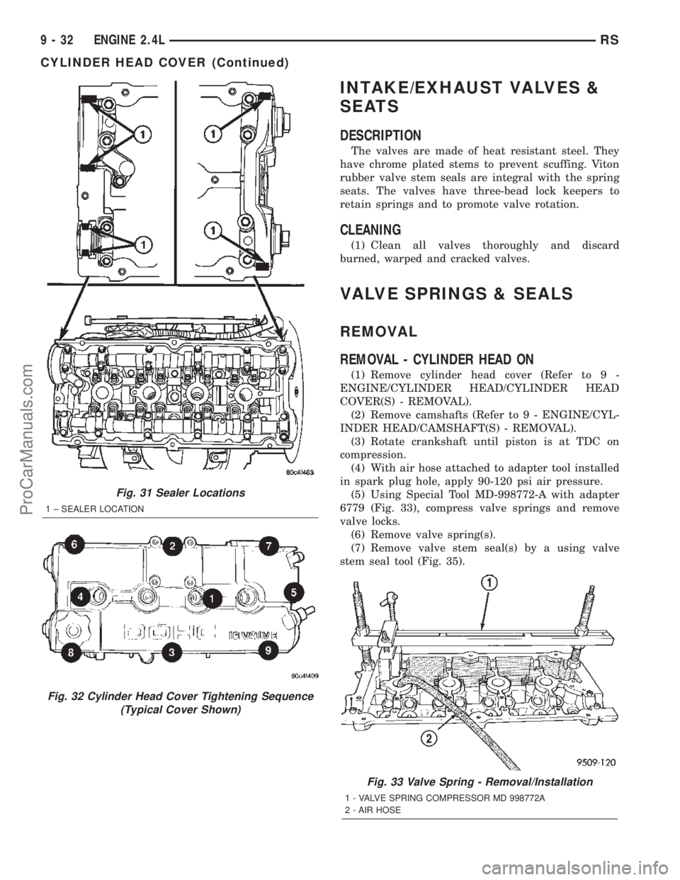
(5) Using Special Tool MD-998772-A with adapter
6779 (Fig. 33), compress valve springs and remove
valve locks.
(6) Remove valve spring(s).
(7) Remove valve stem seal(s) by a using valve
stem seal tool (Fig. 35).
Fig. 31 Sealer Locations
1 ± SEALER LOCATION
Fig. 32 Cylinder Head Cover Tightening Sequence
(Typical Cover Shown)
Fig. 33 Valve Spring - Removal/Installation
1 - VALVE SPRING COMPRESSOR MD 998772A
2 - AIR HOSE
9 - 32 ENGINE 2.4LRS
CYLINDER HEAD COVER (Continued)
ProCarManuals.com