compressor CHRYSLER VOYAGER 2002 Workshop Manual
[x] Cancel search | Manufacturer: CHRYSLER, Model Year: 2002, Model line: VOYAGER, Model: CHRYSLER VOYAGER 2002Pages: 2399, PDF Size: 57.96 MB
Page 1470 of 2399

The PCM compares the upstream and downstream
heated oxygen sensor inputs to measure catalytic con-
vertor efficiency. If the catalyst efficiency drops below
the minimum acceptable percentage, the PCM stores a
diagnostic trouble code in memory, after 2 trips.
During certain idle conditions, the PCM may enter
a variable idle speed strategy. During variable idle
speed strategy the PCM adjusts engine speed based
on the following inputs.
²A/C sense
²Battery voltage
²Battery temperature or Calculated Battery Tem-
perature
²Engine coolant temperature
²Engine run time
²Inlet/Intake air temperature
²Vehicle mileage
ACCELERATION MODE
This is a CLOSED LOOP mode. The PCM recog-
nizes an abrupt increase in Throttle Position sensor
output voltage or MAP sensor output voltage as a
demand for increased engine output and vehicle
acceleration. The PCM increases injector pulse width
in response to increased fuel demand.
²Wide Open Throttle-open loop
DECELERATION MODE
This is a CLOSED LOOP mode. During decelera-
tion the following inputs are received by the PCM:
²A/C sense
²Battery voltage
²Inlet/Intake air temperature
²Engine coolant temperature
²Crankshaft position (engine speed)
²Exhaust gas oxygen content (upstream heated
oxygen sensor)
²Knock sensor
²Manifold absolute pressure
²Throttle position sensor
²IAC motor (solenoid) control changes in response
to MAP sensor feedback
The PCM may receive a closed throttle input from
the Throttle Position Sensor (TPS) when it senses an
abrupt decrease in manifold pressure. This indicates a
hard deceleration (Open Loop). In response, the PCM
may momentarily turn off the injectors. This helps
improve fuel economy, emissions and engine braking.
WIDE-OPEN-THROTTLE MODE
This is an OPEN LOOP mode. During wide-open-
throttle operation, the following inputs are used by
the PCM:
²Inlet/Intake air temperature
²Engine coolant temperature
²Engine speed
²Knock sensor²Manifold absolute pressure
²Throttle position
When the PCM senses a wide-open-throttle condi-
tion through the Throttle Position Sensor (TPS) it de-
energizes the A/C compressor clutch relay. This
disables the air conditioning system and disables
EGR (if equipped).
The PCM adjusts injector pulse width to supply a
predetermined amount of additional fuel, based on
MAP and RPM.
IGNITION SWITCH OFF MODE
When the operator turns the ignition switch to the
OFF position, the following occurs:
²All outputs are turned off, unless 02 Heater
Monitor test is being run. Refer to the Emission sec-
tion for On-Board Diagnostics.
²No inputs are monitored except for the heated
oxygen sensors. The PCM monitors the heating ele-
ments in the oxygen sensors and then shuts down.
FUEL CORRECTION or ADAPTIVE MEMORIES
DESCRIPTION
In Open Loop, the PCM changes pulse width with-
out feedback from the O2 Sensors. Once the engine
warms up to approximately 30 to 35É F, the PCM
goes into closed loopShort Term Correctionand
utilizes feedback from the O2 Sensors. Closed loop
Long Term Adaptive Memoryis maintained above
170É to 190É F unless the PCM senses wide open
throttle. At that time the PCM returns to Open Loop
operation.
OPERATION
Short Term
The first fuel correction program that begins func-
tioning is the short term fuel correction. This system
corrects fuel delivery in direct proportion to the read-
ings from the Upstream O2 Sensor.
The PCM monitors the air/fuel ratio by using the
input voltage from the O2 Sensor. When the voltage
reaches its preset high or low limit, the PCM begins
to add or remove fuel until the sensor reaches its
switch point. The short term corrections then begin.
The PCM makes a series of quick changes in the
injector pulse-width until the O2 Sensor reaches its
opposite preset limit or switch point. The process
then repeats itself in the opposite direction.
Short term fuel correction will keep increasing or
decreasing injector pulse-width based upon the
upstream O2 Sensor input. The maximum range of
authority for short term memory is 25% (+/-) of base
pulse-width. Short term is violated and is lost when
ignition is turned OFF.
RSFUEL INJECTION14-19
FUEL INJECTION (Continued)
ProCarManuals.com
Page 1478 of 2399

FUEL PUMP RELAY
DESCRIPTION
The fuel pump relay is located in the PDC. The
inside top of the PDC cover has a label showing relay
and fuse location.
OPERATION
The fuel pump relay supplies battery voltage to the
fuel pump. A buss bar in the Power Distribution Cen-
ter (PDC) supplies voltage to the solenoid side and
contact side of the relay. The fuel pump relay power
circuit contains a fuse between the buss bar in the
PDC and the relay. The fuse is located in the PDC.
Refer to the Wiring Diagrams for circuit information.
The PCM controls the fuel pump relay by switch-
ing the ground path for the solenoid side of the relay
on and off. The PCM turns the ground path off when
the ignition switch is in the Off position. When the
ignition switch is in the On position, the PCM ener-
gizes the fuel pump. If the crankshaft position sensor
does not detect engine rotation, the PCM de-ener-
gizes the relay after approximately one second.
IDLE AIR CONTROL MOTOR
DESCRIPTION
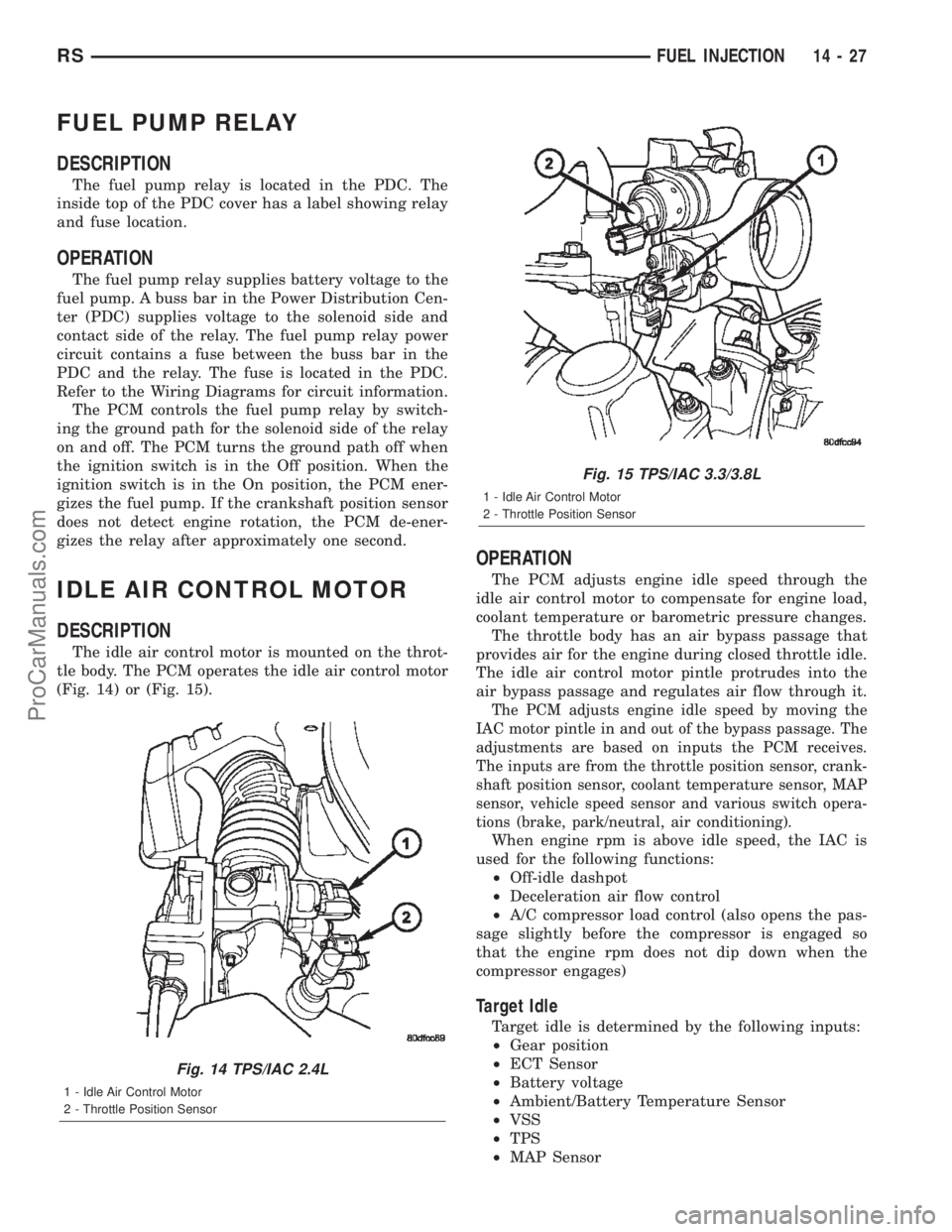
The idle air control motor is mounted on the throt-
tle body. The PCM operates the idle air control motor
(Fig. 14) or (Fig. 15).
OPERATION
The PCM adjusts engine idle speed through the
idle air control motor to compensate for engine load,
coolant temperature or barometric pressure changes.
The throttle body has an air bypass passage that
provides air for the engine during closed throttle idle.
The idle air control motor pintle protrudes into the
air bypass passage and regulates air flow through it.
The PCM adjusts engine idle speed by moving the
IAC motor pintle in and out of the bypass passage. The
adjustments are based on inputs the PCM receives.
The inputs are from the throttle position sensor, crank-
shaft position sensor, coolant temperature sensor, MAP
sensor, vehicle speed sensor and various switch opera-
tions (brake, park/neutral, air conditioning).
When engine rpm is above idle speed, the IAC is
used for the following functions:
²Off-idle dashpot
²Deceleration air flow control
²A/C compressor load control (also opens the pas-
sage slightly before the compressor is engaged so
that the engine rpm does not dip down when the
compressor engages)
Target Idle
Target idle is determined by the following inputs:
²Gear position
²ECT Sensor
²Battery voltage
²Ambient/Battery Temperature Sensor
²VSS
²TPS
²MAP Sensor
Fig. 14 TPS/IAC 2.4L
1 - Idle Air Control Motor
2 - Throttle Position Sensor
Fig. 15 TPS/IAC 3.3/3.8L
1 - Idle Air Control Motor
2 - Throttle Position Sensor
RSFUEL INJECTION14-27
ProCarManuals.com
Page 1632 of 2399

SPECIAL TOOLS
31TH AUTOMATIC TRANSAXLE
Adapter Blocks C-293±45
Adapter Blocks C-293±52
Puller Press C-293±PA
Pressure Gauge (High) C-3293SP
Dial Indicator C-3339
Spring Compressor C-3575-A
Band Adjusting Adapter C-3705
Oil Pump Puller C-3752
Throttle Setting Gauge C-3763
Seal Puller C-3981B
RS31TH AUTOMATIC TRANSAXLE21-75
31TH AUTOMATIC TRANSAXLE (Continued)
ProCarManuals.com
Page 1640 of 2399

(3) Remove clutch pack (Fig. 116).
(4) Using tool C3575A, compress front clutch
return spring and remove snap ring (Fig. 117).(5) Remove retainer, return spring and piston (Fig.
118) (Fig. 119).
Fig. 116 Front Clutch (4-Disc Shown)
1 - FRONT CLUTCH RETAINER
2 - CLUTCH PLATES
3 - DRIVING DISCS
Fig. 117 Front Clutch Return Spring Snap Ring
1 - COMPRESSOR TOOL C-3575-A
2 - FRONT CLUTCH RETAINER
3 - SNAP RING
4 - SNAP RING PLIERS
Fig. 118 Front Clutch Return Spring and Piston
1 - LIP SEALS
2 - PISTON
3 - RETURN SPRING RETAINER
4 - SNAP RING
5 - PISTON RETURN SPRING
6 - FRONT CLUTCH RETAINER
RS31TH AUTOMATIC TRANSAXLE21-83
CLUTCH - FRONT (Continued)
ProCarManuals.com
Page 1642 of 2399

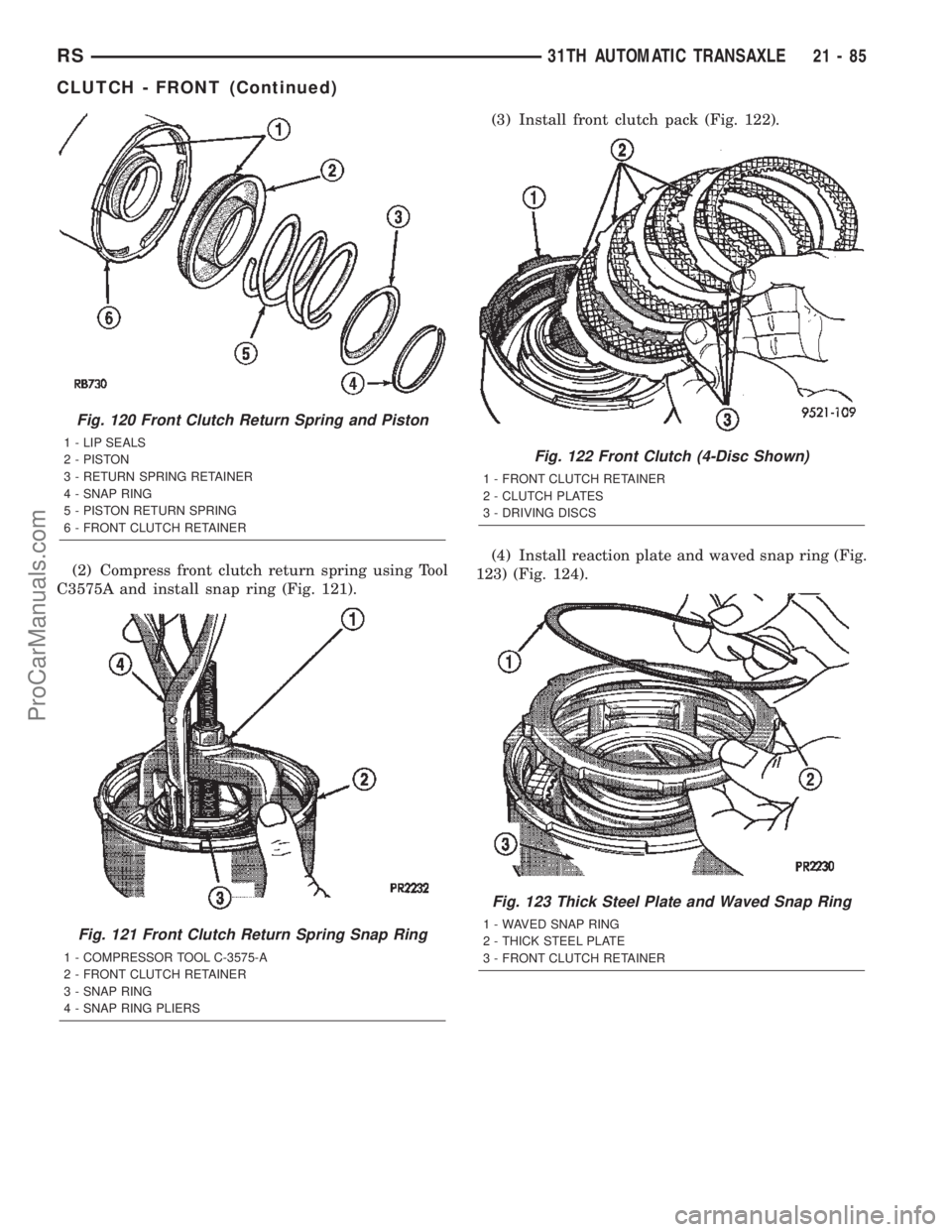
(2) Compress front clutch return spring using Tool
C3575A and install snap ring (Fig. 121).(3) Install front clutch pack (Fig. 122).
(4) Install reaction plate and waved snap ring (Fig.
123) (Fig. 124).
Fig. 120 Front Clutch Return Spring and Piston
1 - LIP SEALS
2 - PISTON
3 - RETURN SPRING RETAINER
4 - SNAP RING
5 - PISTON RETURN SPRING
6 - FRONT CLUTCH RETAINER
Fig. 121 Front Clutch Return Spring Snap Ring
1 - COMPRESSOR TOOL C-3575-A
2 - FRONT CLUTCH RETAINER
3 - SNAP RING
4 - SNAP RING PLIERS
Fig. 122 Front Clutch (4-Disc Shown)
1 - FRONT CLUTCH RETAINER
2 - CLUTCH PLATES
3 - DRIVING DISCS
Fig. 123 Thick Steel Plate and Waved Snap Ring
1 - WAVED SNAP RING
2 - THICK STEEL PLATE
3 - FRONT CLUTCH RETAINER
RS31TH AUTOMATIC TRANSAXLE21-85
CLUTCH - FRONT (Continued)
ProCarManuals.com
Page 1744 of 2399

(57) Install low/reverse spring compressor tool as
shown in (Fig. 74) (Fig. 75).(58) Compress low/reverse piston return spring
and remove snap ring (Fig. 76).
(59) Remove low/reverse spring compressor tool
and low reverse piston return spring (Fig. 77).
Fig. 74 Low/Reverse Spring Compressor Tool
1 - TOOL 6057
2 - TOOL 5059
3 - TOOL 5058±3
Fig. 75 Compressor Tool in Use
1 - LOW/REVERSE CLUTCH RETURN SPRING
2 - SNAP RING (INSTALL AS SHOWN)
3 - TOOL 6057
4 - TOOL 5059
5 - TOOL 5058±3
Fig. 76 Remove Snap Ring
1 - SNAP RING OPENING MUST BE BETWEEN SPRING
LEVERS (AS SHOWN)
2 - SNAP RING PLIERS
3 - TOOL 6057
Fig. 77 Low/Reverse Piston Return Spring
1 - LOW/REVERSE PISTON RETURN SPRING
2 - PISTON
RS41TE AUTOMATIC TRANSAXLE21 - 187
41TE AUTOMATIC TRANSAXLE (Continued)
ProCarManuals.com
Page 1750 of 2399

(10) Install low/reverse spring compressor into
position (Fig. 97). Compress low/reverse piston and
install snap ring as shown in (Fig. 98).(11) Install rear carrier bearing cone using Tool
6053 (Fig. 99).
(12) Install rear carrier assembly to transaxle case
(Fig. 100).
Fig. 97 Compressor Tool in Use
1 - LOW/REVERSE CLUTCH RETURN SPRING
2 - SNAP RING (INSTALL AS SHOWN)
3 - TOOL 6057
4 - TOOL 5059
5 - TOOL 5058±3
Fig. 98 Install Snap Ring
1 - SNAP RING OPENING MUST BE BETWEEN SPRING
LEVERS (AS SHOWN)
2 - SNAP RING PLIERS
3 - TOOL 6057
Fig. 99 Install Rear Carrier Bearing Cone
1 - ARBOR PRESS RAM
2 - TOOL 6053
3 - NEW BEARING CONE
4 - REAR CARRIER ASSEMBLY
Fig. 100 Install Rear Carrier Assembly
1 - REAR CARRIER ASSEMBLY
RS41TE AUTOMATIC TRANSAXLE21 - 193
41TE AUTOMATIC TRANSAXLE (Continued)
ProCarManuals.com
Page 1790 of 2399

Compressor 5058A
Compressor 5059-A
Installer 5067
Pliers 6051
Installer 6052
Installer 6053
Button 6055
Plate 6056
RS41TE AUTOMATIC TRANSAXLE21 - 233
41TE AUTOMATIC TRANSAXLE (Continued)
ProCarManuals.com
Page 1822 of 2399

(8) Install UD piston return spring and Tool 5067
as shown in (Fig. 263).
(9) Using Tool 5059A and an arbor press, Install
the UD spring retainer and snap ring. (Fig. 264) (Fig.
265) Compress just enough to install snap ring.
CAUTION: Compress return spring just enough to
install snap ring.(10) Install the UD clutch pack. Leave out upper
disc, until snap ring is installed (Fig. 266).
Fig. 263 Seal Compressor Special Tool 5067
1 - PISTON RETURN SPRING
2 - SPECIAL TOOL 5067
3 - INPUT SHAFT CLUTCHES RETAINER ASSEMBLY
Fig. 264 UD Return Spring and Retainer
1 - UNDERDRIVE SPRING RETAINER
2 - SNAP RING
3 - SEAL
4 - PISTON RETURN SPRING
Fig. 265 Install UD Spring Retainer and Snap Ring
1 - ARBOR PRESS RAM
2 - SNAP RING PLIERS
3 - SNAP RING
4 - OD/REVERSE PISTON
5 - TOOL 5067
6 - TOOL 5059A
Fig. 266 Underdrive Clutch Pack
1 - CLUTCH PLATE
2 - ONE UD CLUTCH DISC
3 - CLUTCH DISC
RS41TE AUTOMATIC TRANSAXLE21 - 265
INPUT CLUTCH ASSEMBLY (Continued)
ProCarManuals.com
Page 2246 of 2399

pressed, the set temp value will become 55 but the
display will show LO. If the set temp is 85 and the
up button is pressed, the set temp value will become
90 but the display will show HIGH. Temperatures
can be displayed in either metric or Fahrenheit,
which is controlled from the overhead console.
²A rocker switch that selects a cool-down rate.
LO-AUTO or HI-AUTO are displayed when the sys-
tem is in automatic operation.
²A defroster button which turns on the defroster
independently during full automatic control. A
defroster symbol illuminates in the display when the
button is pressed.
²Air recirculation button. A Recirculation symbol
appears in the display when the button is pressed, or
when the system exceeds 80 percent circulated air
under automatic control due to high air conditioning
demand.
²Rear window defogger on/off switch. A graphic
symbol shows when the defroster is on.
²An air conditioning button that allows the com-
pressor to be turned off. A Snowflake symbol is illu-
minated when air conditioning is on, whether under
manual or automatic control.
²Rotary knob for front fan speed selection can
override the automatic controls. LEDs surrounding
the knob show the current setting.
²Rotary knob for control of the Rear system.
²A rotary knob for mode control can override the
automatic controls. LEDs surrounding the knob show
the current setting.
²Computer logic remembers the settings of the
controls when the ignition is turned off and retains
those settings after a restart. If the system is off
when the ignition is turned off it will be off when the
engine is restarted, etc.
²Computer logic provides variable air recircula-
tion under high temperature and humidity condi-
tions. Because recirculation is generally accompanied
by increased fan noise, the proportion of recirculated
to outside air gradually approaches full recirculation
over a broad temperature range.
²A graphic symbol of the windshield that illumi-
nates when the windshield wiper deicer is active.
REAR CONTROL PANEL
A rear control panel centrally mounted on the
headliner includes a vacuum-flourescent digital dis-
play, a rocker control for temperature and rotary con-
trols for adjustment of mode and fan speed control of
the rear unit by intermediate seat passengers.
OPERATION
OPERATION - DUAL ZONE
²The mode control knob enables continously vari-
able proportioning of air flow between modes but has
detents adjacent to each icon.
²The blower control provides five separate speeds.
²When the fan is off, the HVAC computer closes
the recirculation door to prevent outside air from
entering the passenger compartment.
²Interior air may be recirculated to speed up
heating or cooling in all modes except defrost and
mix by pressing the Recirculate button on the control
panel.
²To reduce humidity for rapid defogging the A/C
compressor runs automatically in modes from ªmix'
to full defrost when outside temperatures are above
freezing.
²Air conditioning is available in any mode by
pressing the snowflake, A/C on/off, button.
OPERATION - MANUAL THREE ZONE
FRONT CONTROL PANEL
²Primary control of the rear compartment unit is
on the instrument panel. This control allows the
driver to set the rear compartment fan speed, to turn
the rear unit off, or to give control to the intermedi-
ate seat occupants by switching to the REAR posi-
tion. When the rear unit is controlled from the
instrument panel, rear air temperature is based on
the driver-side temperature control position, and the
mode (floor or overhead air) is based on the front
control's mode position.
²The mode control knob enables continously vari-
able proportioning of air flow between modes but has
detents adjacent to each icon.
²The blower control provides five separate speeds
and Off. When the fan is off, the HVAC computer
closes the recirculation door to prevent outside air
from entering the passenger compartment.
²Interior air may be recirculated to speed up
heating or cooling in all modes exccept defrost and
mix by pressing the Recirculate button on the control
panel.
²To reduce humidity for rapid defogging the A/C
compressor runs automatically in modes from ªmix'
to full defrost when outside temperatures are above
freezing.
²Air conditioning is available in any mode by
pressing the snowflake, A/C on/off, button.
RSHEATING & AIR CONDITIONING24-3
HEATING & AIR CONDITIONING (Continued)
ProCarManuals.com