electr CHRYSLER VOYAGER 2002 Owner's Guide
[x] Cancel search | Manufacturer: CHRYSLER, Model Year: 2002, Model line: VOYAGER, Model: CHRYSLER VOYAGER 2002Pages: 2399, PDF Size: 57.96 MB
Page 243 of 2399
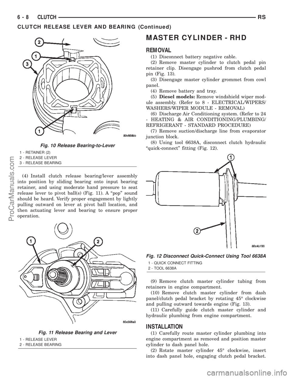
(4) Install clutch release bearing/lever assembly
into position by sliding bearing onto input bearing
retainer, and using moderate hand pressure to seat
release lever to pivot ball(s) (Fig. 11). A ªpopº sound
should be heard. Verify proper engagement by lightly
pulling outward on lever at pivot ball location, and
then actuating lever and bearing to ensure proper
operation.
MASTER CYLINDER - RHD
REMOVAL
(1) Disconnect battery negative cable.
(2) Remove master cylinder to clutch pedal pin
retainer clip. Disengage pushrod from clutch pedal
pin (Fig. 13).
(3) Disengage master cylinder grommet from cowl
panel.
(4) Remove battery and tray.
(5)Diesel models:Remove windshield wiper mod-
ule assembly. (Refer to 8 - ELECTRICAL/WIPERS/
WASHERS/WIPER MODULE - REMOVAL)
(6) Discharge Air Conditioning system. (Refer to 24
- HEATING & AIR CONDITIONING/PLUMBING/
REFRIGERANT - STANDARD PROCEDURE)
(7) Remove suction/discharge line from evaporator
junction block.
(8) Using tool 6638A, disconnect clutch hydraulic
ªquick-connectº fitting (Fig. 12).
(9) Remove clutch master cylinder tubing from
retainers in engine compartment.
(10) Remove clutch master cylinder from dash
panel/clutch pedal bracket by rotating 45É clockwise
and pulling outward towards engine (Fig. 13).
(11) Carefully guide clutch master cylinder and
hydraulic plumbing from engine compartment.
INSTALLATION
(1) Carefully route master cylinder plumbing into
engine compartment as removed and position master
cylinder to dash panel hole.
(2) Rotate master cylinder 45É clockwise, insert
into dash panel hole, engaging clutch pedal bracket.
Fig. 10 Release Bearing-to-Lever
1 - RETAINER (2)
2 - RELEASE LEVER
3 - RELEASE BEARING
Fig. 11 Release Bearing and Lever
1 - RELEASE LEVER
2 - RELEASE BEARING
Fig. 12 Disconnect Quick-Connect Using Tool 6638A
1 - QUICK CONNECT FITTING
2 - TOOL 6638A
6 - 8 CLUTCHRS
CLUTCH RELEASE LEVER AND BEARING (Continued)
ProCarManuals.com
Page 244 of 2399

Rotate master cylinder 45É counter-clockwise, secur-
ing it to pedal bracket (Fig. 13).
(3) Install and secure grommet to dash panel.
(4) Connect pushrod to clutch pedal pin. Install
retainer clip (Fig. 13).
(5) Secure master cylinder plumbing to retainers
in engine compartment.
(6) Connect clutch master cylinder plumbing to
slave cylinder ªquick connectº fitting. An audible
ªclickº should be heard. Verify connection by pulling
outward.
(7) Connect A/C suction/discharge line to evapora-
tor junction block.
(8)Diesel models:Install wiper module assembly.
(Refer to 8 - ELECTRICAL/WIPERS/WASHERS/
WIPER MODULE - INSTALLATION)
(9) Install battery and tray.
(10) Connect battery negative cable
(11) Charge Air Conditioning system. (Refer to 24 -
HEATING & AIR CONDITIONING/PLUMBING/RE-
FRIGERANT - STANDARD PROCEDURE)
MASTER CYLINDER - LHD
REMOVAL
(1) Disconnect battery cables.
(2) Remove instrument panel lower silencer (Fig.
14).
(3) Remove knee bolster (Fig. 15).
Fig. 13 Clutch Master Cylinder at Pedal Bracket
1 - CLUTCH MASTER CYLINDER
2 - RETAINER CLIP
3 - CLUTCH PEDAL PIN
4 - PUSH RODFig. 14 Instrument Panel Lower Silencer
1 - INSTRUMENT PANEL LOWER SILENCER
Fig. 15 Knee Bolster
1 - KNEE BOLSTER
RSCLUTCH6-9
MASTER CYLINDER - RHD (Continued)
ProCarManuals.com
Page 245 of 2399
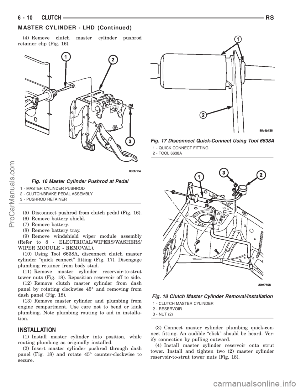
(4) Remove clutch master cylinder pushrod
retainer clip (Fig. 16).
(5) Disconnect pushrod from clutch pedal (Fig. 16).
(6) Remove battery shield.
(7) Remove battery.
(8) Remove battery tray.
(9) Remove windshield wiper module assembly
(Refer to 8 - ELECTRICAL/WIPERS/WASHERS/
WIPER MODULE - REMOVAL).
(10) Using Tool 6638A, disconnect clutch master
cylinder ªquick connectº fitting (Fig. 17). Disengage
plumbing retainer from body stud.
(11) Remove master cylinder reservoir-to-strut
tower nuts (Fig. 18). Reposition reservoir off to side.
(12) Remove clutch master cylinder from dash
panel by rotating clockwise 45É and removing from
dash panel (Fig. 18).
(13) Remove master cylinder and plumbing from
engine compartment. Use care not to bend or kink
plumbing. Note plumbing routing to aid in installa-
tion.
INSTALLATION
(1) Install master cylinder into position, while
routing plumbing as originally installed.
(2) Insert master cylinder pushrod through dash
panel (Fig. 18) and rotate 45É counter-clockwise to
secure.(3) Connect master cylinder plumbing quick-con-
nect fitting. An audible ªclickº should be heard. Ver-
ify connection by pulling outward.
(4) Install master cylinder reservoir onto strut
tower. Install and tighten two (2) master cylinder
reservoir-to-strut tower nuts (Fig. 18).
Fig. 16 Master Cylinder Pushrod at Pedal
1 - MASTER CYLINDER PUSHROD
2 - CLUTCH/BRAKE PEDAL ASSEMBLY
3 - PUSHROD RETAINER
Fig. 17 Disconnect Quick-Connect Using Tool 6638A
1 - QUICK CONNECT FITTING
2 - TOOL 6638A
Fig. 18 Clutch Master Cylinder Removal/Installation
1 - CLUTCH MASTER CYLINDER
2 - RESERVOIR
3 - NUT (2)
6 - 10 CLUTCHRS
MASTER CYLINDER - LHD (Continued)
ProCarManuals.com
Page 246 of 2399
(5) Install windshield wiper module assembly
(Refer to 8 - ELECTRICAL/WIPERS/WASHERS/
WIPER MODULE - INSTALLATION).
(6) Install battery tray.
(7) Install battery.
(8) Install battery shield.
(9) Connect master cylinder pushrod to clutch
pedal lever (Fig. 16). Install retainer clip.
(10) Install knee bolster and instrument panel
lower silencer (Fig. 15) (Fig. 14).
(11) Connect battery cables.
MODULAR CLUTCH ASSY -
2.4L GAS
REMOVAL
(1) Remove transaxle from vehicle. (Refer to 21 -
TRANSMISSION/TRANSAXLE/MANUAL -
REMOVAL)
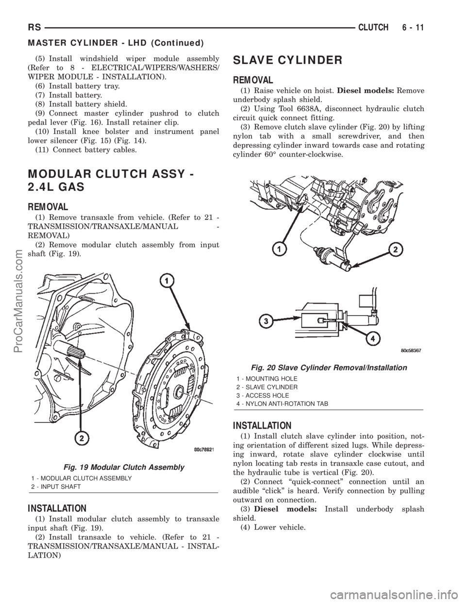
(2) Remove modular clutch assembly from input
shaft (Fig. 19).
INSTALLATION
(1) Install modular clutch assembly to transaxle
input shaft (Fig. 19).
(2) Install transaxle to vehicle. (Refer to 21 -
TRANSMISSION/TRANSAXLE/MANUAL - INSTAL-
LATION)
SLAVE CYLINDER
REMOVAL
(1) Raise vehicle on hoist.Diesel models:Remove
underbody splash shield.
(2) Using Tool 6638A, disconnect hydraulic clutch
circuit quick connect fitting.
(3) Remove clutch slave cylinder (Fig. 20) by lifting
nylon tab with a small screwdriver, and then
depressing cylinder inward towards case and rotating
cylinder 60É counter-clockwise.
INSTALLATION
(1) Install clutch slave cylinder into position, not-
ing orientation of different sized lugs. While depress-
ing inward, rotate slave cylinder clockwise until
nylon locating tab rests in transaxle case cutout, and
the hydraulic tube is vertical (Fig. 20).
(2) Connect ªquick-connectº connection until an
audible ªclickº is heard. Verify connection by pulling
outward on connection.
(3)Diesel models:Install underbody splash
shield.
(4) Lower vehicle.
Fig. 19 Modular Clutch Assembly
1 - MODULAR CLUTCH ASSEMBLY
2 - INPUT SHAFT
Fig. 20 Slave Cylinder Removal/Installation
1 - MOUNTING HOLE
2 - SLAVE CYLINDER
3 - ACCESS HOLE
4 - NYLON ANTI-ROTATION TAB
RSCLUTCH6-11
MASTER CYLINDER - LHD (Continued)
ProCarManuals.com
Page 250 of 2399
COOLING
TABLE OF CONTENTS
page page
COOLING
DESCRIPTION
DESCRIPTION - COOLING SYSTEM........1
DESCRIPTION - HOSE CLAMPS...........1
OPERATION
OPERATION - COOLING SYSTEM.........2
OPERATION - HOSE CLAMPS............2
DIAGNOSIS AND TESTING
DIAGNOSIS AND TESTING - COOLING
SYSTEM LEAK TEST....................2
DIAGNOSIS AND TESTING - COOLING
SYSTEM FLOW CHECK.................3
DIAGNOSIS AND TESTING - COOLING
SYSTEM AERATION....................4
DIAGNOSIS AND TESTING - COOLING
SYSTEM DEAERATION..................4
STANDARD PROCEDURE
STANDARD PROCEDURE - COOLING
SYSTEM DRAINING....................4STANDARD PROCEDURE - COOLING
SYSTEM FILLING......................4
STANDARD PROCEDURE - ADDING
ADDITIONAL COOLANT.................4
STANDARD PROCEDURE - COOLANT
LEVEL CHECK........................5
SPECIFICATIONS
COOLING SYSTEM CAPACITY............6
ACCESSORY DRIVE BELT TENSION.......6
TORQUE.............................6
SPECIAL TOOLS
COOLING SYSTEM.....................7
ACCESSORY DRIVE.......................8
ENGINE...............................14
TRANSMISSION.........................38
COOLING
DESCRIPTION
DESCRIPTION - COOLING SYSTEM
The cooling system components consist of a radia-
tor, electric fan motors, shroud, pressure cap, thermo-
stat, transmission oil cooler, water pump, hoses,
clamps, coolant, and a coolant reserve system to com-
plete the circuit.
DESCRIPTION - HOSE CLAMPS
The cooling system uses spring type hose clamps.
If a spring type clamp replacement is necessary,
replace with the original Mopartequipment spring
type clamp.
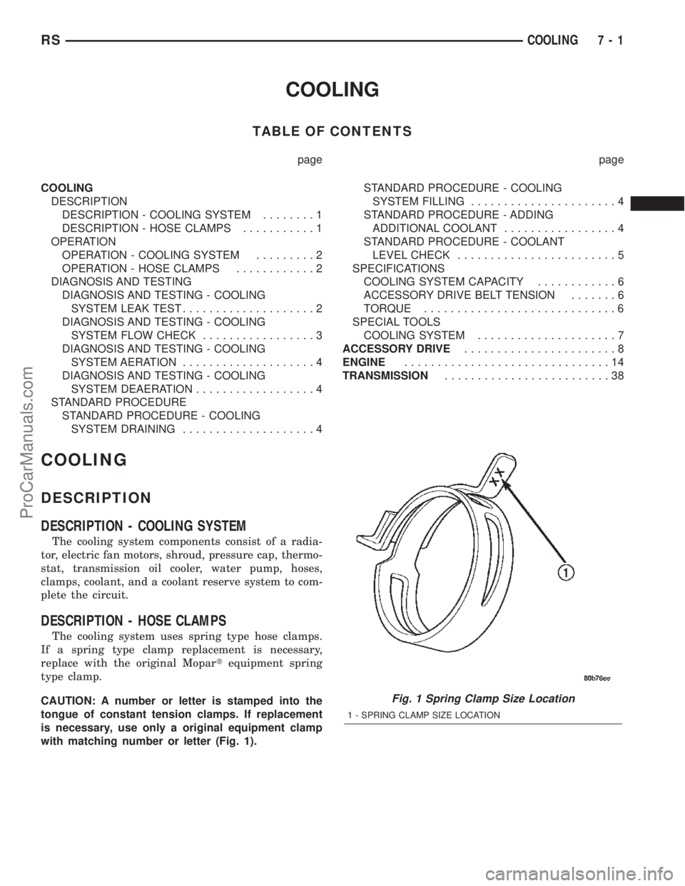
CAUTION: A number or letter is stamped into the
tongue of constant tension clamps. If replacement
is necessary, use only a original equipment clamp
with matching number or letter (Fig. 1).
Fig. 1 Spring Clamp Size Location
1 - SPRING CLAMP SIZE LOCATION
RSCOOLING7-1
ProCarManuals.com
Page 264 of 2399
ENGINE
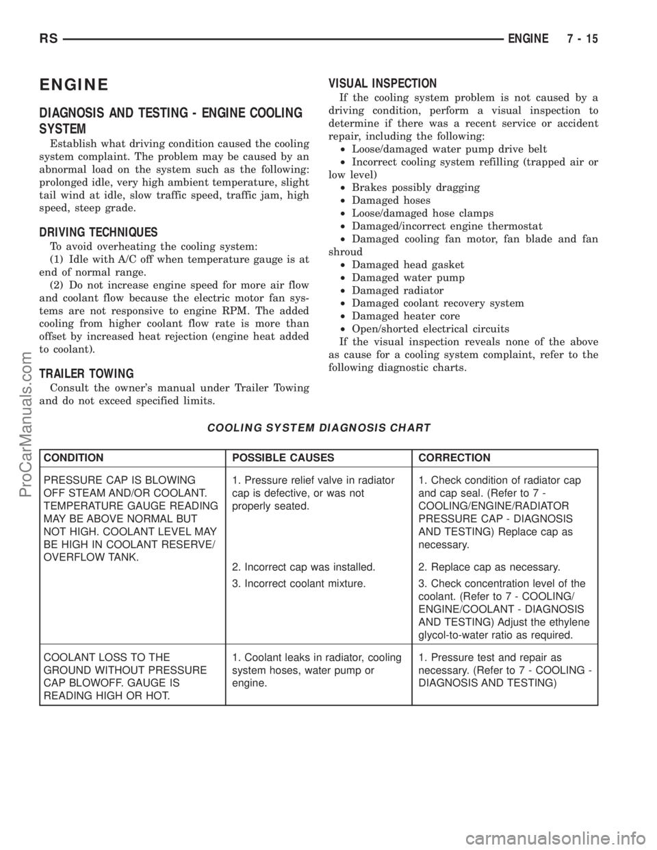
DIAGNOSIS AND TESTING - ENGINE COOLING
SYSTEM
Establish what driving condition caused the cooling
system complaint. The problem may be caused by an
abnormal load on the system such as the following:
prolonged idle, very high ambient temperature, slight
tail wind at idle, slow traffic speed, traffic jam, high
speed, steep grade.
DRIVING TECHNIQUES
To avoid overheating the cooling system:
(1) Idle with A/C off when temperature gauge is at
end of normal range.
(2) Do not increase engine speed for more air flow
and coolant flow because the electric motor fan sys-
tems are not responsive to engine RPM. The added
cooling from higher coolant flow rate is more than
offset by increased heat rejection (engine heat added
to coolant).
TRAILER TOWING
Consult the owner's manual under Trailer Towing
and do not exceed specified limits.
VISUAL INSPECTION
If the cooling system problem is not caused by a
driving condition, perform a visual inspection to
determine if there was a recent service or accident
repair, including the following:
²Loose/damaged water pump drive belt
²Incorrect cooling system refilling (trapped air or
low level)
²Brakes possibly dragging
²Damaged hoses
²Loose/damaged hose clamps
²Damaged/incorrect engine thermostat
²Damaged cooling fan motor, fan blade and fan
shroud
²Damaged head gasket
²Damaged water pump
²Damaged radiator
²Damaged coolant recovery system
²Damaged heater core
²Open/shorted electrical circuits
If the visual inspection reveals none of the above
as cause for a cooling system complaint, refer to the
following diagnostic charts.
COOLING SYSTEM DIAGNOSIS CHART
CONDITION POSSIBLE CAUSES CORRECTION
PRESSURE CAP IS BLOWING
OFF STEAM AND/OR COOLANT.
TEMPERATURE GAUGE READING
MAY BE ABOVE NORMAL BUT
NOT HIGH. COOLANT LEVEL MAY
BE HIGH IN COOLANT RESERVE/
OVERFLOW TANK.1. Pressure relief valve in radiator
cap is defective, or was not
properly seated.1. Check condition of radiator cap
and cap seal. (Refer to 7 -
COOLING/ENGINE/RADIATOR
PRESSURE CAP - DIAGNOSIS
AND TESTING) Replace cap as
necessary.
2. Incorrect cap was installed. 2. Replace cap as necessary.
3. Incorrect coolant mixture. 3. Check concentration level of the
coolant. (Refer to 7 - COOLING/
ENGINE/COOLANT - DIAGNOSIS
AND TESTING) Adjust the ethylene
glycol-to-water ratio as required.
COOLANT LOSS TO THE
GROUND WITHOUT PRESSURE
CAP BLOWOFF. GAUGE IS
READING HIGH OR HOT.1. Coolant leaks in radiator, cooling
system hoses, water pump or
engine.1. Pressure test and repair as
necessary. (Refer to 7 - COOLING -
DIAGNOSIS AND TESTING)
RSENGINE7-15
ProCarManuals.com
Page 265 of 2399
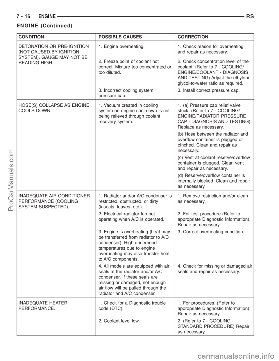
CONDITION POSSIBLE CAUSES CORRECTION
DETONATION OR PRE-IGNITION
(NOT CAUSED BY IGNITION
SYSTEM). GAUGE MAY NOT BE
READING HIGH.1. Engine overheating. 1. Check reason for overheating
and repair as necessary.
2. Freeze point of coolant not
correct. Mixture too concentrated or
too diluted.2. Check concentration level of the
coolant. (Refer to 7 - COOLING/
ENGINE/COOLANT - DIAGNOSIS
AND TESTING) Adjust the ethylene
glycol-to-water ratio as required.
3. Incorrect cooling system
pressure cap.3. Install correct pressure cap.
HOSE(S) COLLAPSE AS ENGINE
COOLS DOWN.1. Vacuum created in cooling
system on engine cool-down is not
being relieved through coolant
recovery system.1. (a) Pressure cap relief valve
stuck. (Refer to 7 - COOLING/
ENGINE/RADIATOR PRESSURE
CAP - DIAGNOSIS AND TESTING)
Replace as necessary.
(b) Hose between the radiator and
overflow container is plugged or
pinched. Clean and repair as
necessary.
(c) Vent at coolant reserve/overflow
container is plugged. Clean vent
and repair as necessary.
(d) Reserve/overflow container is
internally blocked. Clean and repair
as necessary.
INADEQUATE AIR CONDITIONER
PERFORMANCE (COOLING
SYSTEM SUSPECTED).1. Radiator and/or A/C condenser is
restricted, obstructed, or dirty
(insects, leaves, etc.).1. Remove restriction and/or clean
as necessary.
2. Electrical radiator fan not
operating when A/C is operated.2. For test procedure (Refer to
appropriate Diagnostic Information).
Repair as necessary.
3. Engine is overheating (heat may
be transferred from radiator to A/C
condenser). High underhood
temperatures due to engine
overheating may also transfer heat
to A/C components.3. Correct overheating condition.
4. All models are equipped with air
seals at the radiator and/or A/C
condenser. If these seals are
missing or damaged, not enough
air flow will be pulled through the
radiator and A/C condenser.4. Check for missing or damaged air
seals and repair as necessary.
INADEQUATE HEATER
PERFORMANCE.1. Check for a Diagnostic trouble
code (DTC).1. For procedures, (Refer to
appropriate Diagnostic Information).
Repair as necessary.
2. Coolant level low. 2. (Refer to 7 - COOLING -
STANDARD PROCEDURE) Repair
as necessary.
7 - 16 ENGINERS
ENGINE (Continued)
ProCarManuals.com
Page 267 of 2399

CONDITION POSSIBLE CAUSES CORRECTION
COOLANT COLOR 1. Coolant color is not necessarily
an indication of adequate corrosion
or temperature protection. Do not
rely on coolant color for determining
condition of coolant.1. Check the freeze point of the
coolant. (Refer to 7 - COOLING/
ENGINE/COOLANT - DIAGNOSIS
AND TESTING) Adjust the ethylene
glycol-to-water ratio as necessary.
COOLANT LEVEL CHANGES IN
COOLANT BOTTLE.
TEMPERATURE GAUGE IS IN
NORMAL RANGE.1. Level changes are to be
expected as coolant volume
fluctuates with engine temperature.
The coolant level will also drop as
the system removes air from a
recent filling.1. A normal condition. No repair is
necessary.
Refer to (Fig. 1) when using the TEMPERATURE
GAUGE INDICATION DIAGNOSIS CHART.
TEMPERATURE GAUGE INDICATION DIAGNOSIS CHART
CONDITION POSSIBLE CAUSES CORRECTION
TEMPERATURE GAUGE READING
IS INCONSISTENT (FLUCTUATES,
CYCLES OR IS ERRATIC).1. Normal reaction to fan and/or
thermostat cycle (Fig. 1 ),
Examples B and C. During cold
weather operation with the heater
blower in the high position, the
gauge reading may drop slightly
(Fig. 1 ), Example D. Fluctuation is
also influenced by outside
temperature and heavy loads (Fig.
1 ), Example E.1. A normal condition. No correction
is necessary.
2. Gauge reading rises when
vehicle is brought to a stop after
heavy use (engine still running)
(Fig. 1 ), Example F.2. A normal condition. No correction
is necessary. Gauge reading should
return to normal range (Fig. 1 ),
Example A, after vehicle is driven.
3. Gauge reading high after
restarting a warmed-up (hot)
engine.3. A normal condition. No correction
is necessary. The gauge should
return to normal range (Fig. 1 ),
Example A, after a few minutes of
engine operation.
4. Temperature gauge or engine
coolant temperature sensor
defective or shorted. Also, corroded
or loose wiring in the electrical
circuit.4. Check operation of gauge or
engine coolant temperature sensor
and repair, if necessary.
7 - 18 ENGINERS
ENGINE (Continued)
ProCarManuals.com
Page 270 of 2399
ENGINE BLOCK HEATER
DESCRIPTION
The engine block heater is available as an optional
accessory on all models. The heater is operated by
ordinary house current (110 Volt A.C.) through a
power cord located behind the radiator grille. This
provides easier engine starting and faster warm-up
when vehicle is operated in areas having extremely
low temperatures. The heater is mounted in a core
hole (in place of a core hole plug) in the engine block,
with the heating element immersed in coolant.
OPERATION
The block heater element is submerged in the cool-
ing system's coolant. When electrical power (110 volt
A.C.) is applied to the element, it creates heat. This
heat is transferred to the engine coolant. This pro-
vides easier engine starting and faster warm-up
when vehicle is operated in areas having extremely
low temperatures.
DIAGNOSIS AND TESTING - ENGINE BLOCK
HEATER TESTING
If unit does not operate, trouble can be in either
the power cord or the heater element. Test power
cord for continuity with a 110-volt voltmeter or 110-
volt test light; test heater element continuity with an
ohmmeter or 12-volt test light.
REMOVAL
(1) Drain coolant from radiator and cylinder block.
(Refer to 7 - COOLING - STANDARD PROCEDURE)
(2) Disconnect the power cord plug from heater.
(3) Loosen screw in center of heater. Remove the
heater assembly.
INSTALLATION
(1) Clean block core hole and heater seat.
(2) Insert heater assembly with element loop posi-
tionedupward.
(3) With heater seated, tighten center screw
securely to assure a positive seal.
(4) Install power cord plug to heater.
(5) Fill cooling system with coolant to the proper
level. (Refer to 7 - COOLING - STANDARD PROCE-
DURE)
ENGINE COOLANT
TEMPERATURE SENSOR - 2.4L
DESCRIPTION
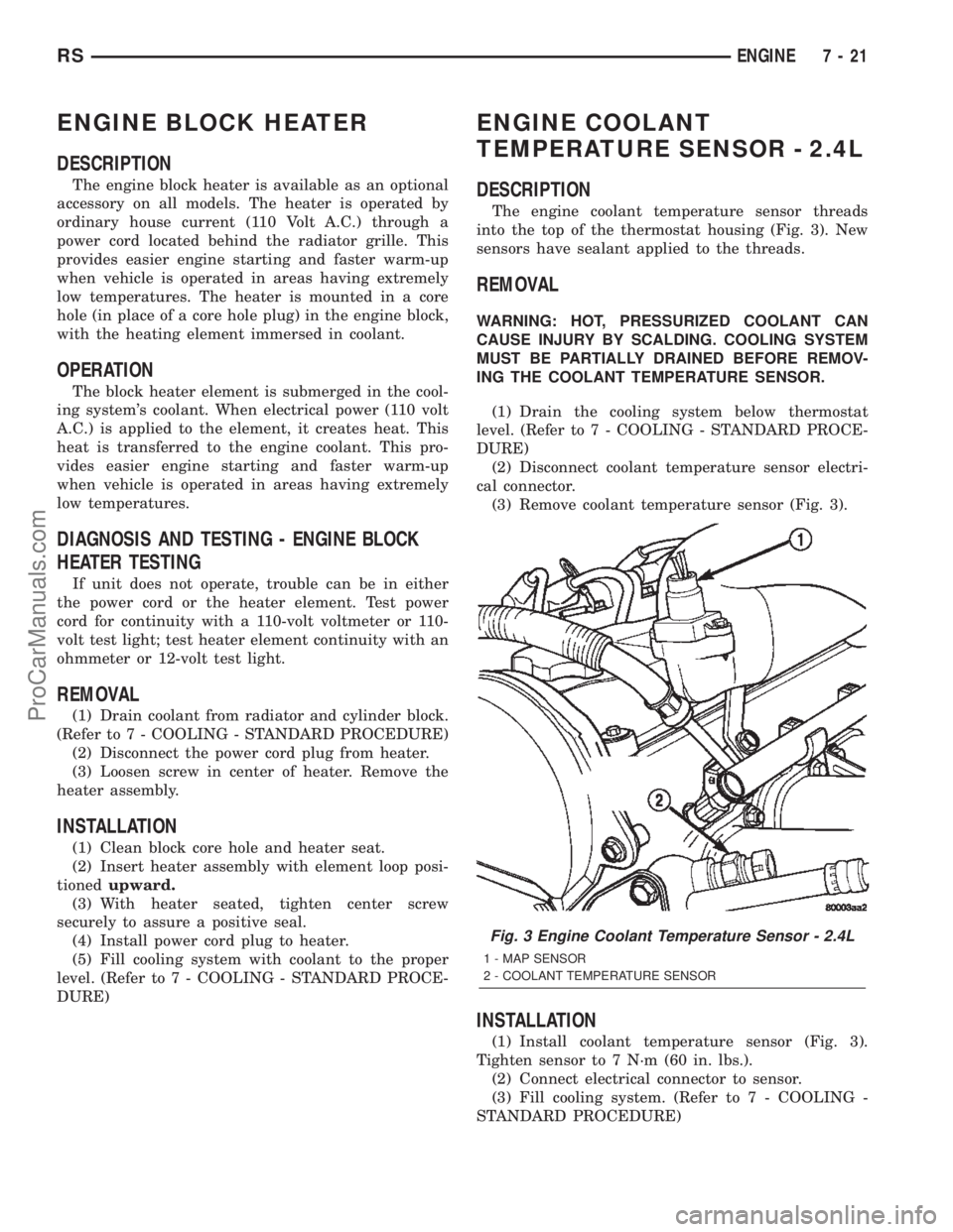
The engine coolant temperature sensor threads
into the top of the thermostat housing (Fig. 3). New
sensors have sealant applied to the threads.
REMOVAL
WARNING: HOT, PRESSURIZED COOLANT CAN
CAUSE INJURY BY SCALDING. COOLING SYSTEM
MUST BE PARTIALLY DRAINED BEFORE REMOV-
ING THE COOLANT TEMPERATURE SENSOR.
(1) Drain the cooling system below thermostat
level. (Refer to 7 - COOLING - STANDARD PROCE-
DURE)
(2) Disconnect coolant temperature sensor electri-
cal connector.
(3) Remove coolant temperature sensor (Fig. 3).
INSTALLATION
(1) Install coolant temperature sensor (Fig. 3).
Tighten sensor to 7 N´m (60 in. lbs.).
(2) Connect electrical connector to sensor.
(3) Fill cooling system. (Refer to 7 - COOLING -
STANDARD PROCEDURE)
Fig. 3 Engine Coolant Temperature Sensor - 2.4L
1 - MAP SENSOR
2 - COOLANT TEMPERATURE SENSOR
RSENGINE7-21
ProCarManuals.com
Page 271 of 2399
ENGINE COOLANT
TEMPERATURE SENSOR -
3.3/3.8L
DESCRIPTION
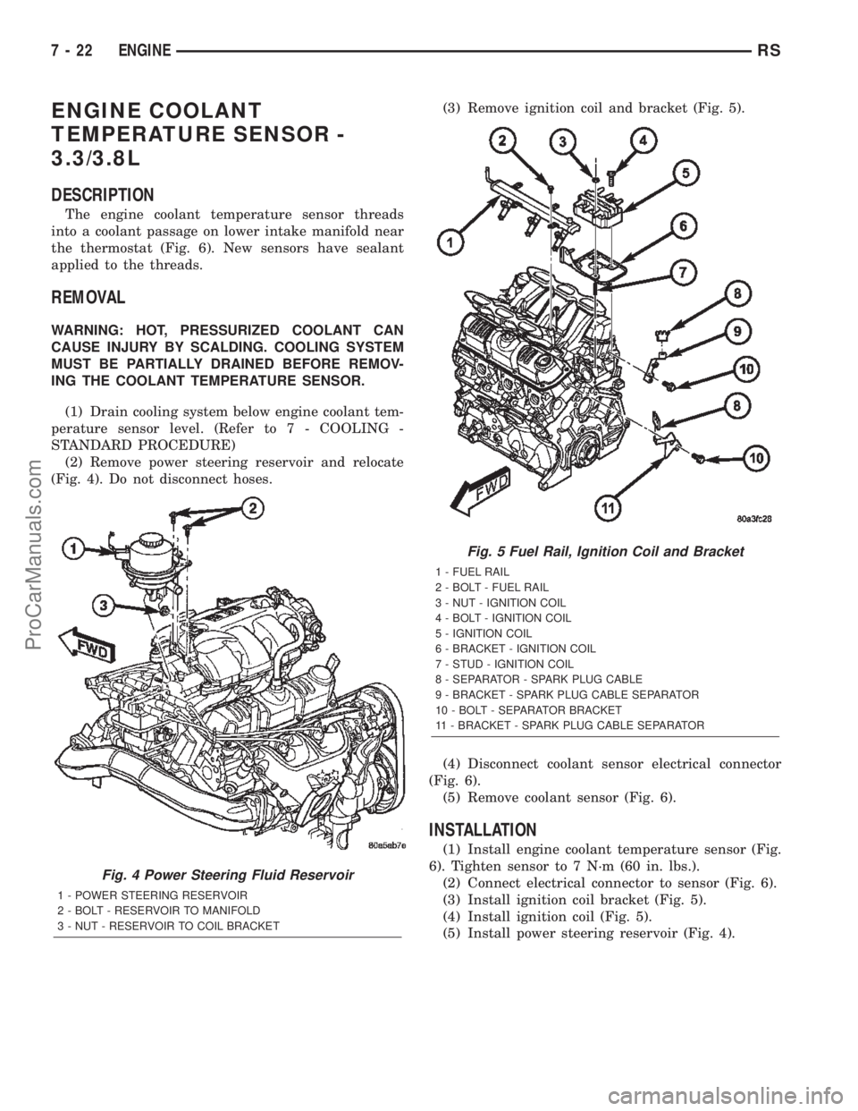
The engine coolant temperature sensor threads
into a coolant passage on lower intake manifold near
the thermostat (Fig. 6). New sensors have sealant
applied to the threads.
REMOVAL
WARNING: HOT, PRESSURIZED COOLANT CAN
CAUSE INJURY BY SCALDING. COOLING SYSTEM
MUST BE PARTIALLY DRAINED BEFORE REMOV-
ING THE COOLANT TEMPERATURE SENSOR.
(1) Drain cooling system below engine coolant tem-
perature sensor level. (Refer to 7 - COOLING -
STANDARD PROCEDURE)
(2) Remove power steering reservoir and relocate
(Fig. 4). Do not disconnect hoses.(3) Remove ignition coil and bracket (Fig. 5).
(4) Disconnect coolant sensor electrical connector
(Fig. 6).
(5) Remove coolant sensor (Fig. 6).
INSTALLATION
(1) Install engine coolant temperature sensor (Fig.
6). Tighten sensor to 7 N´m (60 in. lbs.).
(2) Connect electrical connector to sensor (Fig. 6).
(3) Install ignition coil bracket (Fig. 5).
(4) Install ignition coil (Fig. 5).
(5) Install power steering reservoir (Fig. 4).
Fig. 4 Power Steering Fluid Reservoir
1 - POWER STEERING RESERVOIR
2 - BOLT - RESERVOIR TO MANIFOLD
3 - NUT - RESERVOIR TO COIL BRACKET
Fig. 5 Fuel Rail, Ignition Coil and Bracket
1 - FUEL RAIL
2 - BOLT - FUEL RAIL
3 - NUT - IGNITION COIL
4 - BOLT - IGNITION COIL
5 - IGNITION COIL
6 - BRACKET - IGNITION COIL
7 - STUD - IGNITION COIL
8 - SEPARATOR - SPARK PLUG CABLE
9 - BRACKET - SPARK PLUG CABLE SEPARATOR
10 - BOLT - SEPARATOR BRACKET
11 - BRACKET - SPARK PLUG CABLE SEPARATOR
7 - 22 ENGINERS
ProCarManuals.com