torque CHRYSLER VOYAGER 2003 Service Manual
[x] Cancel search | Manufacturer: CHRYSLER, Model Year: 2003, Model line: VOYAGER, Model: CHRYSLER VOYAGER 2003Pages: 2177, PDF Size: 59.81 MB
Page 1629 of 2177

INPUT SHAFT
DESCRIPTION METRIC SPECIFICATION
End Play 0.127-0.635mm 0.005-0.025 in.
TORQUE SPECIFICATIONS
DESCRIPTION N´m Ft. Lbs. In. Lbs.
Bolt, Differential Cover-to-Case 19 Ð 165
Bolt, Differential Ring Gear-to-Case 95 70 Ð
Bolt, Differential Bearing Retainer-to-
Case28 21 Ð
Bolt, Driveplate-to-Crankshaft 95 70 Ð
Bolt, Extension Housing/Plate-to-Case 28 21 Ð
Bolt, Oil Pan-to-Case 19 Ð 165
Bolt, Output Gear 271 200 Ð
Bolt, Output Gear Stirrup/Strap 23 17 Ð
Bolt, Oil Pump-to-Case 27 20 Ð
Bolt, Reaction Support-to-Case 27 20 Ð
Bolt, Solenoid/Pressure Switch
Assy.-to-Case12 Ð 110
Bolt, Torque Converter-to-Driveplate 75 55 Ð
Bolt, Transfer Gear Cover 20 Ð 175
Bolt, Valve Body-to-Case 12 Ð 105
Fitting, Oil Cooler Line 12 Ð 105
Nut, Tranfer Gear 271 200 Ð
Tap, Transaxle Pressure 5 Ð 45
Screw, L/R Clutch Retainer 5 Ð 45
Screw, Solenoid/Pressure Switch Assy.
Connector4Ð35
Screw, Valve Body-to-Transfer Plate 5 Ð 45
Sensor, Input Speed 27 20 Ð
Sensor, Output Speed 27 20 Ð
Sensor, Transmission Range Sensor 5 Ð 45
21 - 182 41TE AUTOMATIC TRANSAXLERS
41TE AUTOMATIC TRANSAXLE (Continued)
ProCarManuals.com
Page 1638 of 2177

The transfer shaft should be removed for differen-
tial repair and bearing turning torque checking.
(1) Remove the differential cover and bolts (Fig.
173) (Fig. 174).(2) Remove the differential bearing retainer and
bolts (Fig. 175) (Fig. 176).
(3) Using a plastic hammer, remove extension
housing/adapter plate on the right side of the trans-
axle.
WARNING: HOLD ONTO DIFFERENTIAL ASSEMBLY
TO PREVENT IT FROM ROLLING OUT OF HOUSING.
Fig. 173 Differential Cover Bolts
1 - DIFFERENTIAL COVER BOLTS
2 - DIFFERENTIAL COVER
Fig. 174 Remove Differential Cover
1 - DIFFERENTIAL ASSEMBLY
2 - DIFFERENTIAL COVER
Fig. 175 Differential Retainer Bolts
1 - DIFFERENTIAL RETAINER BOLTS
Fig. 176 Remove Bearing Retainer
1 - DIFFERENTIAL BEARING RETAINER
2 - TOOL L-4435
RS41TE AUTOMATIC TRANSAXLE21 - 191
FINAL DRIVE (Continued)
ProCarManuals.com
Page 1644 of 2177
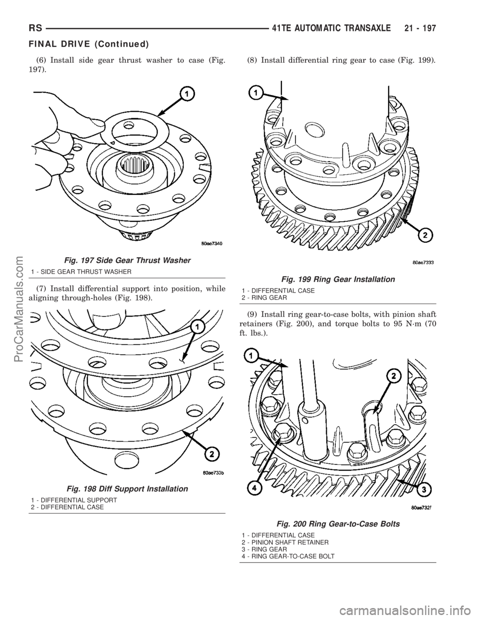
(6) Install side gear thrust washer to case (Fig.
197).
(7) Install differential support into position, while
aligning through-holes (Fig. 198).(8) Install differential ring gear to case (Fig. 199).
(9) Install ring gear-to-case bolts, with pinion shaft
retainers (Fig. 200), and torque bolts to 95 N´m (70
ft. lbs.).
Fig. 197 Side Gear Thrust Washer
1 - SIDE GEAR THRUST WASHER
Fig. 198 Diff Support Installation
1 - DIFFERENTIAL SUPPORT
2 - DIFFERENTIAL CASE
Fig. 199 Ring Gear Installation
1 - DIFFERENTIAL CASE
2 - RING GEAR
Fig. 200 Ring Gear-to-Case Bolts
1 - DIFFERENTIAL CASE
2 - PINION SHAFT RETAINER
3 - RING GEAR
4 - RING GEAR-TO-CASE BOLT
RS41TE AUTOMATIC TRANSAXLE21 - 197
FINAL DRIVE (Continued)
ProCarManuals.com
Page 1645 of 2177
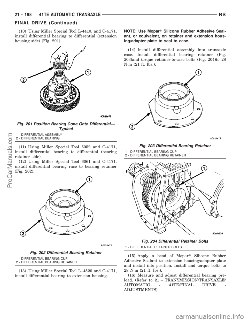
(10) Using Miller Special Tool L-4410, and C-4171,
install differential bearing to differential (extension
housing side) (Fig. 201).
(11) Using Miller Special Tool 5052 and C-4171,
install differential bearing to differential (bearing
retainer side).
(12) Using Miller Special Tool 6061 and C-4171,
install differential bearing race to bearing retainer
(Fig. 202).
(13) Using Miller Special Tool L±4520 and C-4171,
install differential bearing to extension housing.NOTE: Use MoparTSilicone Rubber Adhesive Seal-
ant, or equivalent, on retainer and extension hous-
ing/adapter plate to seal to case.
(14) Install differential assembly into transaxle
case. Install differential bearing retainer (Fig.
203)and torque retainer-to-case bolts (Fig. 204)to 28
N´m (21 ft. lbs.).
(15) Apply a bead of MopartSilicone Rubber
Adhesive Sealant to extension housing/adapter plate
and install into position. Install and torque bolts to
28 N´m (21 ft. lbs.).
(16) Measure and adjust differential bearing pre-
load. (Refer to 21 - TRANSMISSION/TRANSAXLE/
AUTOMATIC - 41TE/FINAL DRIVE -
ADJUSTMENTS)
Fig. 201 Position Bearing Cone Onto DifferentialÐ
Typical
1 - DIFFERENTIAL ASSEMBLY
2 - DIFFERENTIAL BEARING
Fig. 202 Differential Bearing Retainer
1 - DIFFERENTIAL BEARING CUP
2 - DIFFERENTIAL BEARING RETAINER
Fig. 203 Differential Bearing Retainer
1 - DIFFERENTIAL BEARING CUP
2 - DIFFERENTIAL BEARING RETAINER
Fig. 204 Differential Retainer Bolts
1 - DIFFERENTIAL RETAINER BOLTS
21 - 198 41TE AUTOMATIC TRANSAXLERS
FINAL DRIVE (Continued)
ProCarManuals.com
Page 1646 of 2177

(17) Apply a bead of MopartSilicone Rubber
Adhesive Sealant to differential cover and install to
case (Fig. 205).
(18) Install and torque cover-to-case bolts to 19
N´m (165 in. lbs.) (Fig. 206).
ADJUSTMENTS
ADJUSTMENT - DIFFERENTIAL BEARING
PRELOAD
NOTE: Perform all differential bearing preload mea-
surements with the transfer shaft and gear
removed.
DIFFERENTIAL BEARING PRELOAD ADJUSTMENT
USING EXISTING SHIM
(1) Position the transaxle assembly vertically on
the support stand, differential bearing retainer side
up.
(2) Install Tool L-4436A into the differential and
onto the pinion mate shaft (Fig. 207).
(3) Rotate the differential at least one full revolu-
tion to ensure the tapered roller bearings are fully
seated.
(4) Using Tool L-4436A and an inch-pound torque
wrench, check the turning torque of the differential
(Fig. 208).The turning torque should be
between 5 and 18 inch-pounds.
Fig. 205 Install Differential Cover
1 - DIFFERENTIAL ASSEMBLY
2 - DIFFERENTIAL COVER
Fig. 206 Differential Cover Bolts
1 - DIFFERENTIAL COVER BOLTS
2 - DIFFERENTIAL COVER
Fig. 207 Tool L-4436 and Torque Wrench
1 - SPECIAL TOOL L-4436±A
2 - TORQUE WRENCH
3 - DIFFERENTIAL BEARING RETAINER
Fig. 208 Checking Differential Bearings Turning
Torque
1 - SPECIAL TOOL L-4436±A
2 - TORQUE WRENCH
RS41TE AUTOMATIC TRANSAXLE21 - 199
FINAL DRIVE (Continued)
ProCarManuals.com
Page 1647 of 2177
(5) If the turning torque is within specifications,
remove tools. Setup is complete.
(6) If turning torque is not within specifications
proceed with the following steps.
(a) Remove differential bearing retainer from
the transaxle case.
(b) Remove the bearing cup from the differential
bearing retainer using Tool 6062A.
(c) Remove the existing shim from under the
cup.
(d) Measure the existing shim.
(e) If the turning torque was too high when mea-
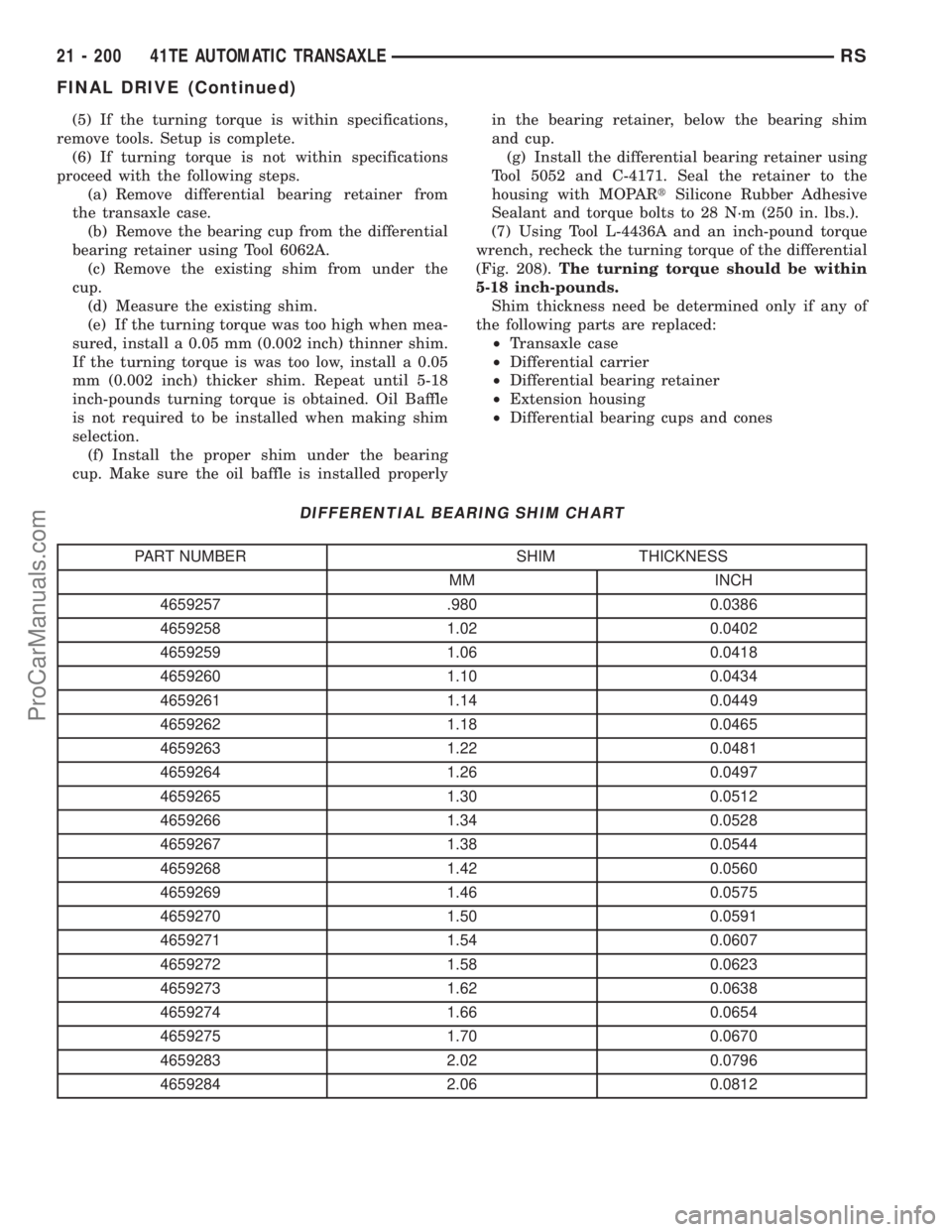
sured, install a 0.05 mm (0.002 inch) thinner shim.
If the turning torque is was too low, install a 0.05
mm (0.002 inch) thicker shim. Repeat until 5-18
inch-pounds turning torque is obtained. Oil Baffle
is not required to be installed when making shim
selection.
(f) Install the proper shim under the bearing
cup. Make sure the oil baffle is installed properlyin the bearing retainer, below the bearing shim
and cup.
(g) Install the differential bearing retainer using
Tool 5052 and C-4171. Seal the retainer to the
housing with MOPARtSilicone Rubber Adhesive
Sealant and torque bolts to 28 N´m (250 in. lbs.).
(7) Using Tool L-4436A and an inch-pound torque
wrench, recheck the turning torque of the differential
(Fig. 208).The turning torque should be within
5-18 inch-pounds.
Shim thickness need be determined only if any of
the following parts are replaced:
²Transaxle case
²Differential carrier
²Differential bearing retainer
²Extension housing
²Differential bearing cups and cones
DIFFERENTIAL BEARING SHIM CHART
PART NUMBER SHIM THICKNESS
MM INCH
4659257 .980 0.0386
4659258 1.02 0.0402
4659259 1.06 0.0418
4659260 1.10 0.0434
4659261 1.14 0.0449
4659262 1.18 0.0465
4659263 1.22 0.0481
4659264 1.26 0.0497
4659265 1.30 0.0512
4659266 1.34 0.0528
4659267 1.38 0.0544
4659268 1.42 0.0560
4659269 1.46 0.0575
4659270 1.50 0.0591
4659271 1.54 0.0607
4659272 1.58 0.0623
4659273 1.62 0.0638
4659274 1.66 0.0654
4659275 1.70 0.0670
4659283 2.02 0.0796
4659284 2.06 0.0812
21 - 200 41TE AUTOMATIC TRANSAXLERS
FINAL DRIVE (Continued)
ProCarManuals.com
Page 1648 of 2177
PRELOAD ADJUSTMENT W/O SHIM
(1) Remove the bearing cup from the differential
bearing retainer using Miller special Tool 6062A.
(2) Remove existing shim from under bearing cup.
(3) Reinstall the bearing cup into the retainer
using Miller Special Tool 6061, and C-4171.
NOTE: Oil baffle is not required when making the
shim calculation.
(4) Install the bearing retainer into the case.
Torque bolts to 28 N´m (250 in. lbs.).
(5) Position the transaxle assembly vertically on
the support stand and install Miller Special Tool
L-4436-A into the bearing retainer.
(6) Rotate the differential at least one full revolu-
tion to ensure the tapered roller bearings are fully
seated.
(7) Attach a dial indicator to the case and zero the
dial. Place the tip on the end of Special Tool
L-4436-A.
(8) Place a large screwdriver to each side of the
ring gear and lift. Check the dial indicator for the
amount of end play.
CAUTION: Do not damage the transaxle case and/or
differential retainer sealing surface.
(9) Using the end play measurement that was
determined, add 0.18mm (0.007 inch). This should
give you between 5-18 inch pounds of bearing pre-
load. Refer to the Differential Bearing Shim Chart to
determine which shim to use.
(10) Remove the differential bearing retainer.
Remove the bearing cup.
(11) Install the oil baffle. Install the proper shim
combination under the bearing cup.
(12) Install the differential bearing retainer. Seal
the retainer to the housing with MopartSilicone
Rubber Adhesive Sealant. Torque bolts to 28 N´m
(250 in. lbs.).
(13) Using Miller Special Tool L-4436-A and an
inch-pound torque wrench, check the turning torque
of the differential (Fig. 208). The turning torque
should be between 5-18 inch-pounds.
NOTE: If turning torque is too high install a 0.05mm
(0.002 inch) thicker shim. If the turning torque is too
low, install a 0.05mm (0.002 inch) thinner shim.
Repeat until 5-18 inch-pounds of turning torque is
obtained.
FLUID
STANDARD PROCEDURE
FLUID LEVEL AND CONDITION CHECK
NOTE: Only transmission fluid of the type labeled
Mopar ATF+4 (Automatic Transmission Fluid)
should be used in this transaxle.
FLUID LEVEL CHECK
The transmission sump has a fluid level indicator
(dipstick) to check oil similar to most automatic
transmissions. It is located on the left side of the
engine. Be sure to wipe all dirt from dipstick handle
before removing.
The torque converter fills in both the P Park and N
Neutral positions. Place the selector lever in P Park
to be sure that the fluid level check is accurate.The
engine should be running at idle speed for at
least one minute, with the vehicle on level
ground.At normal operating temperature 82É C
(180É F), the fluid level is correct if it is in the HOT
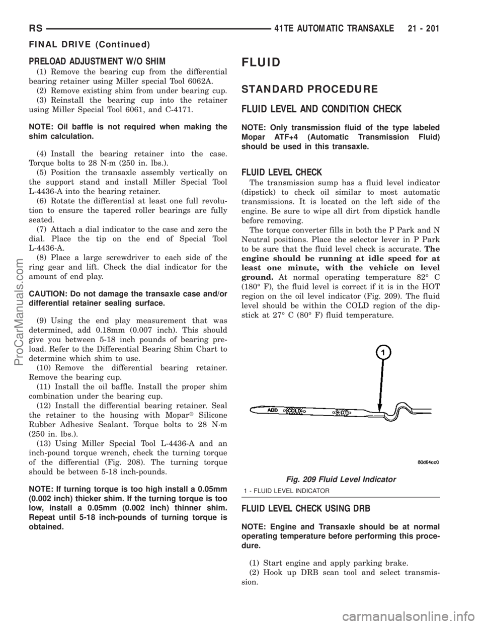
region on the oil level indicator (Fig. 209). The fluid
level should be within the COLD region of the dip-
stick at 27É C (80É F) fluid temperature.
FLUID LEVEL CHECK USING DRB
NOTE: Engine and Transaxle should be at normal
operating temperature before performing this proce-
dure.
(1) Start engine and apply parking brake.
(2) Hook up DRB scan tool and select transmis-
sion.
Fig. 209 Fluid Level Indicator
1 - FLUID LEVEL INDICATOR
RS41TE AUTOMATIC TRANSAXLE21 - 201
FINAL DRIVE (Continued)
ProCarManuals.com
Page 1677 of 2177
OIL PUMP
DESCRIPTION
The oil pump is located in the pump housing inside
the bell housing of the transaxle case (Fig. 283). The
oil pump consists of an inner and outer gear, a hous-
ing, and a cover that also serves as the reaction shaft
support.
OPERATION
As the torque converter rotates, the converter hub
rotates the inner and outer gears. As the gears
rotate, the clearance between the gear teeth
increases in the crescent area, and creates a suction
at the inlet side of the pump. This suction draws
fluid through the pump inlet from the oil pan. As the
clearance between the gear teeth in the crescent area
decreases, it forces pressurized fluid into the pump
outlet and to the valve body.
DISASSEMBLY
When disassembling the transaxle it is necessary
to inspect the oil pump for wear and damage.
(1) Remove the reaction shaft support bolts.
(2) Remove reaction shaft support from pump
housing (Fig. 284).
(3) Remove the pump gears (Fig. 285) and check
for wear and damage on pump housing and gears.
(4) Re-install the gears and check clearances.
(5) Measure the clearance between the outer gear
and the pump pocket (Fig. 286). Clearance should be
0.089±0.202 mm (0.0035-0.0079 in.).
(6) Measure clearance between outer gear and
crescent. Clearance should be 0.060-0.298 mm
(0.0023-0.0117 in.).
(7) Measure clearance between inner gear and
crescent. Clearance should be 0.093-0.385 mm
(0.0036-0.0151 in.).
(8) Position an appropriate piece of Plastigage
across both pump gears.
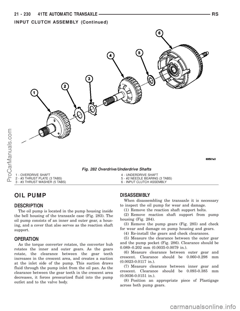
Fig. 282 Overdrive/Underdrive Shafts
1 - OVERDRIVE SHAFT
2 - #3 THRUST PLATE (3 TABS)
3 - #3 THRUST WASHER (5 TABS)4 - UNDERDRIVE SHAFT
5 - #2 NEEDLE BEARING (3 TABS)
6 - INPUT CLUTCH ASSEMBLY
21 - 230 41TE AUTOMATIC TRANSAXLERS
INPUT CLUTCH ASSEMBLY (Continued)
ProCarManuals.com
Page 1679 of 2177
ASSEMBLY
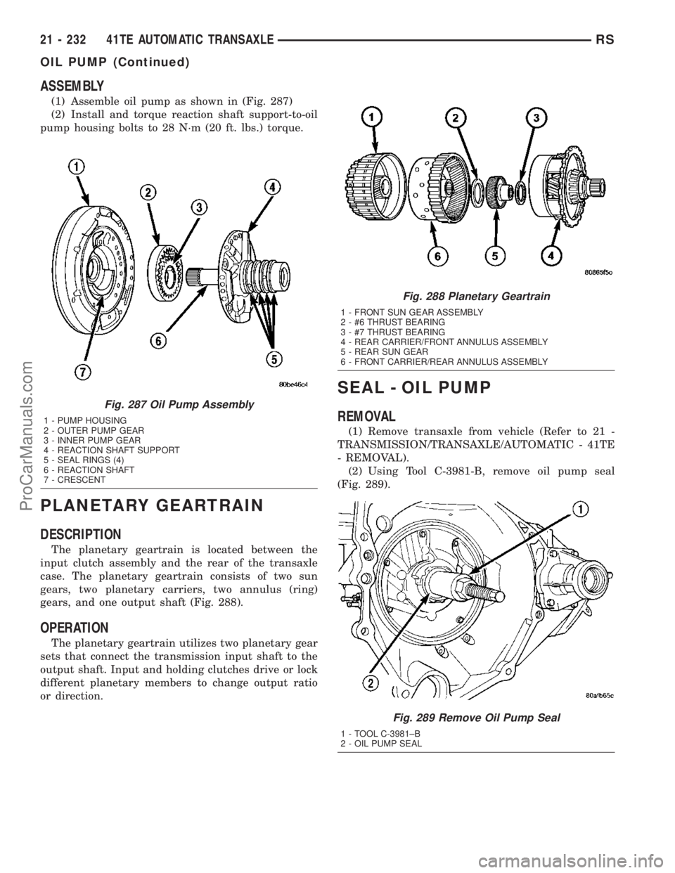
(1) Assemble oil pump as shown in (Fig. 287)
(2) Install and torque reaction shaft support-to-oil
pump housing bolts to 28 N´m (20 ft. lbs.) torque.
PLANETARY GEARTRAIN
DESCRIPTION
The planetary geartrain is located between the
input clutch assembly and the rear of the transaxle
case. The planetary geartrain consists of two sun
gears, two planetary carriers, two annulus (ring)
gears, and one output shaft (Fig. 288).
OPERATION
The planetary geartrain utilizes two planetary gear
sets that connect the transmission input shaft to the
output shaft. Input and holding clutches drive or lock
different planetary members to change output ratio
or direction.
SEAL - OIL PUMP
REMOVAL
(1) Remove transaxle from vehicle (Refer to 21 -
TRANSMISSION/TRANSAXLE/AUTOMATIC - 41TE
- REMOVAL).
(2) Using Tool C-3981-B, remove oil pump seal
(Fig. 289).
Fig. 287 Oil Pump Assembly
1 - PUMP HOUSING
2 - OUTER PUMP GEAR
3 - INNER PUMP GEAR
4 - REACTION SHAFT SUPPORT
5 - SEAL RINGS (4)
6 - REACTION SHAFT
7 - CRESCENT
Fig. 288 Planetary Geartrain
1 - FRONT SUN GEAR ASSEMBLY
2 - #6 THRUST BEARING
3 - #7 THRUST BEARING
4 - REAR CARRIER/FRONT ANNULUS ASSEMBLY
5 - REAR SUN GEAR
6 - FRONT CARRIER/REAR ANNULUS ASSEMBLY
Fig. 289 Remove Oil Pump Seal
1 - TOOL C-3981±B
2 - OIL PUMP SEAL
21 - 232 41TE AUTOMATIC TRANSAXLERS
OIL PUMP (Continued)
ProCarManuals.com
Page 1686 of 2177
INSTALLATION
NOTE: If solenoid/pressure switch assembly is
being replaced, it is necessary to perform the TCM
Quick Learn Procedure. (Refer to 8 - ELECTRICAL/
ELECTRONIC CONTROL MODULES/TRANSMISSION
CONTROL MODULE - STANDARD PROCEDURE)
(1) Install solenoid/pressure switch assembly and
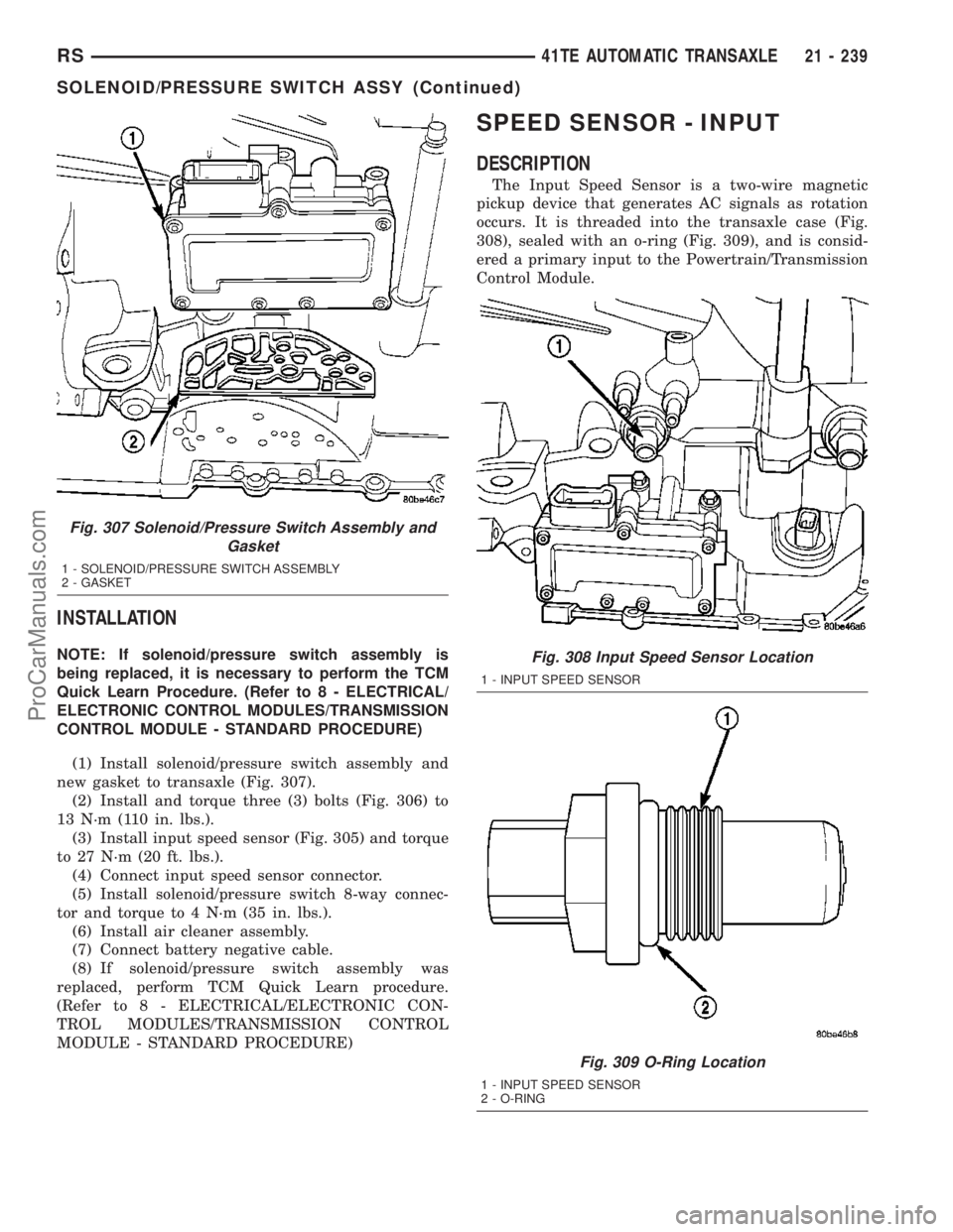
new gasket to transaxle (Fig. 307).
(2) Install and torque three (3) bolts (Fig. 306) to
13 N´m (110 in. lbs.).
(3) Install input speed sensor (Fig. 305) and torque
to 27 N´m (20 ft. lbs.).
(4) Connect input speed sensor connector.
(5) Install solenoid/pressure switch 8-way connec-
tor and torque to 4 N´m (35 in. lbs.).
(6) Install air cleaner assembly.
(7) Connect battery negative cable.
(8) If solenoid/pressure switch assembly was
replaced, perform TCM Quick Learn procedure.
(Refer to 8 - ELECTRICAL/ELECTRONIC CON-
TROL MODULES/TRANSMISSION CONTROL
MODULE - STANDARD PROCEDURE)
SPEED SENSOR - INPUT
DESCRIPTION
The Input Speed Sensor is a two-wire magnetic
pickup device that generates AC signals as rotation
occurs. It is threaded into the transaxle case (Fig.
308), sealed with an o-ring (Fig. 309), and is consid-
ered a primary input to the Powertrain/Transmission
Control Module.
Fig. 307 Solenoid/Pressure Switch Assembly and
Gasket
1 - SOLENOID/PRESSURE SWITCH ASSEMBLY
2 - GASKET
Fig. 308 Input Speed Sensor Location
1 - INPUT SPEED SENSOR
Fig. 309 O-Ring Location
1 - INPUT SPEED SENSOR
2 - O-RING
RS41TE AUTOMATIC TRANSAXLE21 - 239
SOLENOID/PRESSURE SWITCH ASSY (Continued)
ProCarManuals.com