torque CHRYSLER VOYAGER 2004 Service Manual
[x] Cancel search | Manufacturer: CHRYSLER, Model Year: 2004, Model line: VOYAGER, Model: CHRYSLER VOYAGER 2004Pages: 2585, PDF Size: 62.54 MB
Page 604 of 2585
REMOVAL
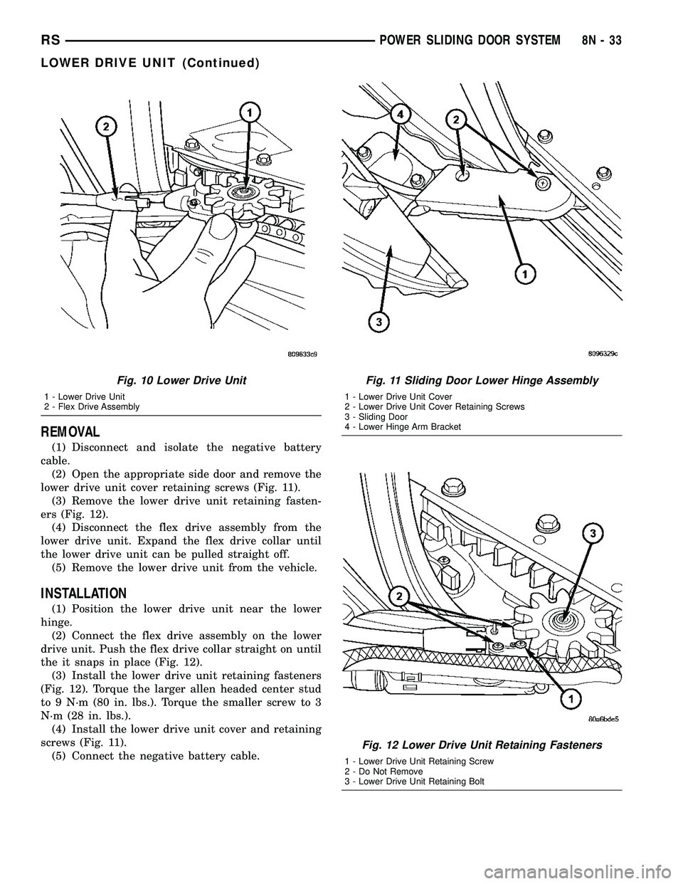
(1) Disconnect and isolate the negative battery
cable.
(2) Open the appropriate side door and remove the
lower drive unit cover retaining screws (Fig. 11).
(3) Remove the lower drive unit retaining fasten-
ers (Fig. 12).
(4) Disconnect the flex drive assembly from the
lower drive unit. Expand the flex drive collar until
the lower drive unit can be pulled straight off.
(5) Remove the lower drive unit from the vehicle.
INSTALLATION
(1) Position the lower drive unit near the lower
hinge.
(2) Connect the flex drive assembly on the lower
drive unit. Push the flex drive collar straight on until
the it snaps in place (Fig. 12).
(3) Install the lower drive unit retaining fasteners
(Fig. 12). Torque the larger allen headed center stud
to 9 N´m (80 in. lbs.). Torque the smaller screw to 3
N´m (28 in. lbs.).
(4) Install the lower drive unit cover and retaining
screws (Fig. 11).
(5) Connect the negative battery cable.
Fig. 10 Lower Drive Unit
1 - Lower Drive Unit
2 - Flex Drive Assembly
Fig. 11 Sliding Door Lower Hinge Assembly
1 - Lower Drive Unit Cover
2 - Lower Drive Unit Cover Retaining Screws
3 - Sliding Door
4 - Lower Hinge Arm Bracket
Fig. 12 Lower Drive Unit Retaining Fasteners
1 - Lower Drive Unit Retaining Screw
2 - Do Not Remove
3 - Lower Drive Unit Retaining Bolt
RSPOWER SLIDING DOOR SYSTEM8N-33
LOWER DRIVE UNIT (Continued)
Page 605 of 2585
LOWER DRIVE UNIT TRACK &
RACK
DESCRIPTION
Vehicles equipped with a power sliding side door
utilize a lower drive unit track or door track and
rack assembly. This track provides a mating rack
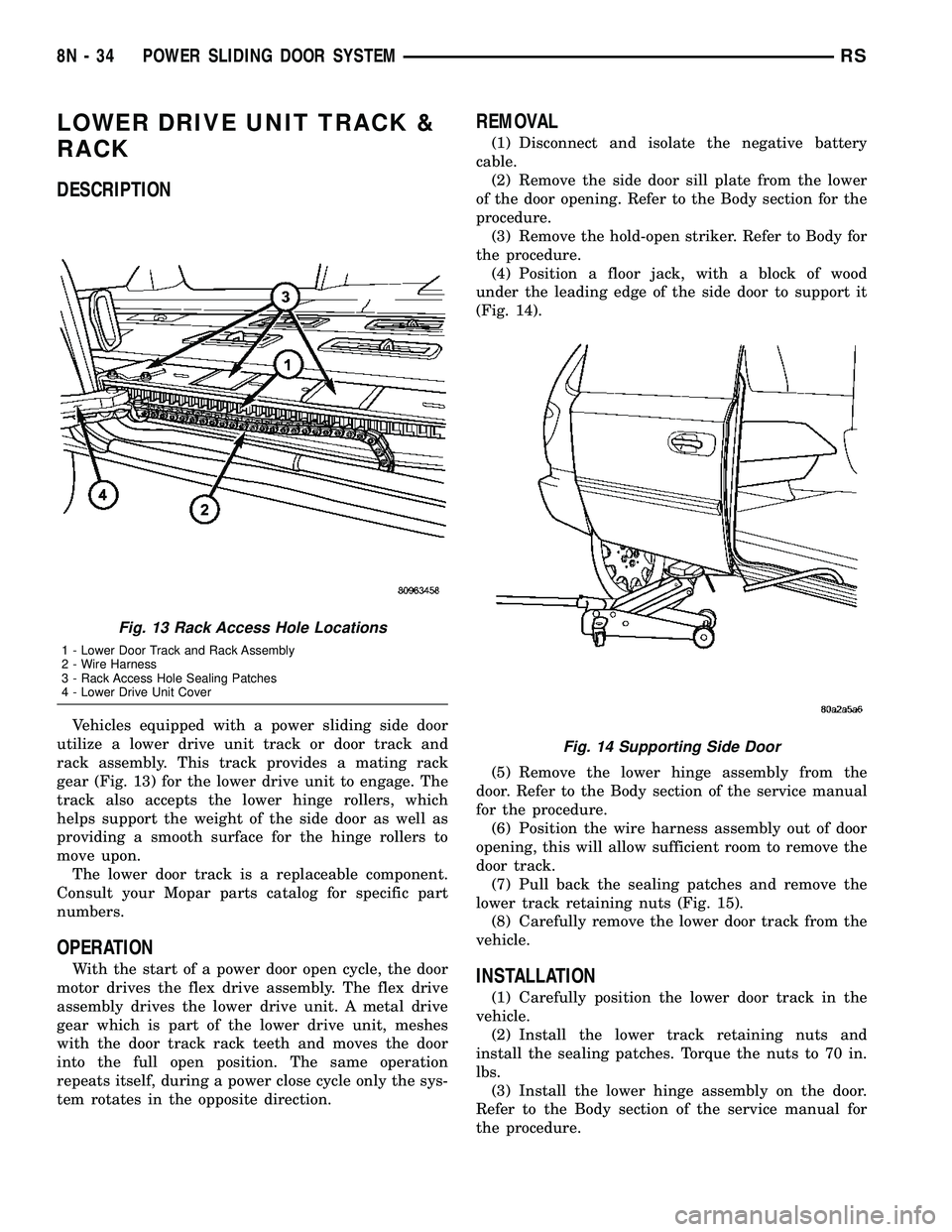
gear (Fig. 13) for the lower drive unit to engage. The
track also accepts the lower hinge rollers, which
helps support the weight of the side door as well as
providing a smooth surface for the hinge rollers to
move upon.
The lower door track is a replaceable component.
Consult your Mopar parts catalog for specific part
numbers.
OPERATION
With the start of a power door open cycle, the door
motor drives the flex drive assembly. The flex drive
assembly drives the lower drive unit. A metal drive
gear which is part of the lower drive unit, meshes
with the door track rack teeth and moves the door
into the full open position. The same operation
repeats itself, during a power close cycle only the sys-
tem rotates in the opposite direction.
REMOVAL
(1) Disconnect and isolate the negative battery
cable.
(2) Remove the side door sill plate from the lower
of the door opening. Refer to the Body section for the
procedure.
(3) Remove the hold-open striker. Refer to Body for
the procedure.
(4) Position a floor jack, with a block of wood
under the leading edge of the side door to support it
(Fig. 14).
(5) Remove the lower hinge assembly from the
door. Refer to the Body section of the service manual
for the procedure.
(6) Position the wire harness assembly out of door
opening, this will allow sufficient room to remove the
door track.
(7) Pull back the sealing patches and remove the
lower track retaining nuts (Fig. 15).
(8) Carefully remove the lower door track from the
vehicle.
INSTALLATION
(1) Carefully position the lower door track in the
vehicle.
(2) Install the lower track retaining nuts and
install the sealing patches. Torque the nuts to 70 in.
lbs.
(3) Install the lower hinge assembly on the door.
Refer to the Body section of the service manual for
the procedure.
Fig. 13 Rack Access Hole Locations
1 - Lower Door Track and Rack Assembly
2 - Wire Harness
3 - Rack Access Hole Sealing Patches
4 - Lower Drive Unit Cover
Fig. 14 Supporting Side Door
8N - 34 POWER SLIDING DOOR SYSTEMRS
Page 607 of 2585

(11) Remove the wire harness assembly from the
vehicle.
INSTALLATION
(1) Position the wire harness assembly in the vehi-
cle.
(2) Connect the wire harness connector located at
the rearward edge of the B-pillar.
(3) Install the side door lower sill plate. Refer to
the Body section for the procedure.
(4) Snap the wire harness retaining pushpins in
the rocker panel.
(5) Slide the wire harness on the lower drive unit
stud.
(6) Install the wire harness retaining clip on the
lower drive unit stud.
(7) Connect the power side door electrical connec-
tor, located just behind the lower drive unit.
(8) Install the lower drive unit cover and retaining
screws.
(9) Install the appropriate door trim panel on the
sliding side door. Refer to the Body section for the
procedure.
(10) Connect the negative battery cable.
FLEX DRIVE
DESCRIPTION
Vehicles equipped with a power sliding side door
utilize a flex drive assembly. The flex drive assembly
is located in the lower portion of the door (Fig. 18)
and is used to connect the door motor to the lower
drive unit. An E-clip is used to secure the flexdrive to
the motor assembly, while the flex drive collar is
used to secure the drive to the lower drive unit. The
flex drive assembly is basically a flexible drive shaft
for the power side door system.
The flex drive assembly is a replaceable compo-
nent. Consult your Mopar parts catalog for specific
part numbers.
OPERATION
With one end of the flex drive attached to the door
motor and the other attached to the lower drive unit,
the flex drive transfers the power and torque from
the motor to the drive unit. A square shaped drive
cable, inside the flex drive assembly engages the
motor drive and rotates to move the door accordingly.
Fig. 17 Lower Hinge/Drive Assembly
1 - Lower Drive Unit Cover
2 - Lower Drive Unit Cover Retaining Screws
3 - Sliding Door
4 - Lower Hinge Arm Bracket
Fig. 18 Side Door Components
1 - Sliding Door Control Module
2 - Module Retaining Screw
3 - Module Electrical Connectors
4 - Door Motor Assembly
5 - Flex Drive Assembly
6 - Door Motor Retaining Fasteners
7 - Door Motor Electrical Connector
8N - 36 POWER SLIDING DOOR SYSTEMRS
WIRING HARNESS (Continued)
Page 630 of 2585
TESTING POWER SEAT TRACK MOTORS
(1) Check the power seat circuit breaker under the
seat. If OK, go to Step 2. If not OK, replace the
faulty power seat circuit breaker.
(2) Check for battery voltage at the power seat cir-
cuit breaker under the seat. If OK, go to Step 3. If
not OK, repair the open fused B(+) circuit to the fuse
in the Intelligent Power Module as required.
(3) Remove the outboard seat cushion side shield
from the seat. Disconnect the seat wire harness con-
nector from the power seat switch connector recepta-
cle. Check for battery voltage at the fused B(+)
circuit cavity of the power seat wire harness connec-
tor for the power seat switch. If OK, go to Step 4. If
not OK, repair the open fused B(+) circuit to the
power seat circuit breaker under the seat as
required.
(4) Check for continuity between the ground cir-
cuit cavity of the power seat wire harness connector
for the power seat switch and a good ground. There
should be continuity. If OK, go to Step 5. If not OK,
repair the open ground circuit to ground as required.
(5) Test the power seat switch. Refer toDiagnosis
and Testing Power Seat Switchin this section. If
the switch tests OK, test the circuits of the power
seat wire harness between the inoperative power seat
track adjuster motor and the power seat switch for
shorts or opens. If the circuits check OK, replace the
faulty power seat track unit. If the circuits are not
OK, repair the power seat wire harness as required.
REMOVAL
WARNING: SOME VEHICLES ARE EQUIPPED WITH
SEATBACK MOUNTED AIRBAGS. BEFORE
ATTEMPTING TO DIAGNOSE OR SERVICE ANY
SEAT OR POWER SEAT SYSTEM COMPONENT
YOU MUST FIRST DISCONNECT AND ISOLATE THE
BATTERY NEGATIVE CABLE. THEN WAIT TWO MIN-
UTES FOR THE SYSTEM CAPACITOR TO DIS-
CHARGE BEFORE FURTHER SYSTEM SERVICE.
THIS IS THE ONLY SURE WAY TO DISABLE THE
AIRBAG SYSTEM. FAILURE TO DO SO COULD
RESULT IN ACCIDENTAL AIRBAG DEPLOYMENT
AND POSSIBLE PERSONAL INJURY.
(1) Remove the appropriate seat from the vehicle
and place it on a clean work surface(Refer to 23 -
BODY/SEATS/SEAT - REMOVAL).
(2) If the vehicle is so equipped, remove the Mem-
ory Seat/Mirror Module (MSMM) retaining screws.
(3) If the vehicle is so equipped, disconnect the
MSMM electrical connectors and remove the MSMM
from the power seat track.
(4) Remove the rear fabric blocker trim panel from
the rear of the front seat.(5) Remove the seat side cover and power seat
switch as an assembly (Refer to 23 - BODY/SEATS/
SEAT CUSHION SIDE COVERS - REMOVAL).
(6) Disconnect all electrical connectors connecting
the power seat track to the seat assembly.
(7) Pull the seat back trim cover up slightly to
access and remove the two seat back frame mounting
bolts and also remove two seat back recliner bolts.
(8) Remove four seat track mounting bolts from
the seat cushion pan.
(9) Remove the power seat track from the seat.
INSTALLATION
(1) Position the seat cushion on the seat track.
(2) Install the four seat track retaining bolts in the
seat cushion pan. Torque the bolts to 28.5 N´m.
(3) Position the seat back and install the two seat
back frame mounting bolts and the two seat back
recliner bolts. Torque the bolts to 55 N´m.
(4) Route and connect the electrical connectors
between the power seat track and the seat assembly.
(5) Install the seat side cover and power seat
switch as an assembly (Refer to 23 - BODY/SEATS/
SEAT CUSHION SIDE COVERS - INSTALLATION).
(6) Install the rear fabric blocker trim panel on the
rear of the front seat.
(7) If the vehicle is so equipped, position the Mem-
ory Seat/Mirror Module (MSMM) and connect the
MSMM electrical connectors.
(8) Install the MSMM retaining screws.
(9) Install the seat assembly in the vehicle (Refer
to 23 - BODY/SEATS/SEAT - INSTALLATION).
PASSENGER POWER SEAT
TRACK
DESCRIPTION
The four-way passenger side power seat option
includes a electrically operated power seat track unit
located under the passenger side front seat. The
power seat circuit breaker is mounted on the rear of
the power seat track, just behind the seat rear trim
panel. The lower half of the power seat track is
secured to the floor panel via four studs and nuts
that must be accessed from the underside of the vehi-
cle. Four bolts secure the bottom of the seat cushion
frame to the upper half of the power seat track unit.
Four additional bolts secure the seat back frame to
the power seat track unit.
The passenger side power seat track unit includes
two reversible electric motors that are secured to the
upper half of the track unit. Each motor moves the
seat adjuster through a combination of worm-drive
gearboxes and screw-type drive units. The horizontal
adjustment motor moves the seat track in the for-
RSPOWER SEAT SYSTEM8N-59
DRIVER POWER SEAT TRACK (Continued)
Page 632 of 2585
REMOVAL
WARNING: SOME VEHICLES ARE EQUIPPED WITH
SEATBACK MOUNTED AIRBAGS. BEFORE
ATTEMPTING TO DIAGNOSE OR SERVICE ANY
SEAT OR POWER SEAT SYSTEM COMPONENT
YOU MUST FIRST DISCONNECT AND ISOLATE THE
BATTERY NEGATIVE CABLE. THEN WAIT TWO MIN-
UTES FOR THE SYSTEM CAPACITOR TO DIS-
CHARGE BEFORE FURTHER SYSTEM SERVICE.
THIS IS THE ONLY SURE WAY TO DISABLE THE
AIRBAG SYSTEM. FAILURE TO DO SO COULD
RESULT IN ACCIDENTAL AIRBAG DEPLOYMENT
AND POSSIBLE PERSONAL INJURY.
(1) Remove the appropriate seat from the vehicle
(Refer to 23 - BODY/SEATS/SEAT - REMOVAL).
(2) Remove the rear fabric blocker trim panel from
the rear of the front seat.
(3) Remove the seat side cover and power seat
switch as an assembly (Refer to 23 - BODY/SEATS/
SEAT CUSHION SIDE COVERS - REMOVAL).
(4) Disconnect all electrical connectors connecting
the power seat track to the seat assembly.(5) Pull the seat back trim cover up slightly to
access and remove the two seat back frame mounting
bolts and seat back recliner bolts.
(6) Remove four seat track mounting bolts from
the seat cushion pan.
(7) Remove the power seat track from the seat.
INSTALLATION
(1) Position the seat cushion on the seat track.
(2) Install the four seat track retaining bolts in the
seat cushion pan. Torque the bolts to 28.5 N´m.
(3) Position the seat back and install the two seat
back frame mounting bolts and the two seat back
recliner bolts. Torque the bolts to 55 N´m.
(4) Route and connect the electrical connectors
between the power seat track and the seat assembly.
(5) Install the seat side cover and power seat
switch as an assembly (Refer to 23 - BODY/SEATS/
SEAT CUSHION - INSTALLATION).
(6) Install the rear fabric blocker trim panel on the
rear of the front seat.
(7) Install the seat assembly in the vehicle (Refer
to 23 - BODY/SEATS/SEAT - INSTALLATION).
RSPOWER SEAT SYSTEM8N-61
PASSENGER POWER SEAT TRACK (Continued)
Page 653 of 2585
and test again to be certain that the adjuster is not
at its travel limit. If the power seat track adjuster
still fails to operate in only one direction, refer to
Diagnosis and Testing Power Seat Switchin this
section. If the power seat track adjuster fails to oper-
ate in more than one direction, perform the following
tests. For complete circuit diagrams, refer to Wiring
Diagrams .
TESTING POWER SEAT TRACK MOTORS
(1) Check the power seat circuit breaker under the
seat. If OK, go to Step 2. If not OK, replace the
faulty power seat circuit breaker. (2) Check for battery voltage at the power seat cir-
cuit breaker under the seat. If OK, go to Step 3. If
not OK, repair the open fused B(+) circuit to the fuse
in the Intelligent Power Module as required. (3) Remove the outboard seat cushion side shield
from the seat. Disconnect the seat wire harness con-
nector from the power seat switch connector recepta-
cle. Check for battery voltage at the fused B(+)
circuit cavity of the power seat wire harness connec-
tor for the power seat switch. If OK, go to Step 4. If
not OK, repair the open fused B(+) circuit to the
power seat circuit breaker under the seat as
required. (4) Check for continuity between the ground cir-
cuit cavity of the power seat wire harness connector
for the power seat switch and a good ground. There
should be continuity. If OK, go to Step 5. If not OK,
repair the open ground circuit to ground as required. (5) Test the power seat switch. Refer to Diagnosis
and Testing Power Seat Switch in this section. If
the switch tests OK, test the circuits of the power
seat wire harness between the inoperative power seat
track adjuster motor and the power seat switch for
shorts or opens. If the circuits check OK, replace the
faulty power seat track unit. If the circuits are not
OK, repair the power seat wire harness as required.
REMOVAL
WARNING: SOME VEHICLES ARE EQUIPPED WITH
SEATBACK MOUNTED AIRBAGS. BEFORE
ATTEMPTING TO DIAGNOSE OR SERVICE ANY
SEAT OR POWER SEAT SYSTEM COMPONENT
YOU MUST FIRST DISCONNECT AND ISOLATE THE
BATTERY NEGATIVE CABLE. THEN WAIT TWO MIN-
UTES FOR THE SYSTEM CAPACITOR TO DIS-
CHARGE BEFORE FURTHER SYSTEM SERVICE.
THIS IS THE ONLY SURE WAY TO DISABLE THE
AIRBAG SYSTEM. FAILURE TO DO SO COULD
RESULT IN ACCIDENTAL AIRBAG DEPLOYMENT
AND POSSIBLE PERSONAL INJURY. (1) Remove the appropriate seat from the vehicle
and place it on a clean work surface(Refer to 23 -
BODY/SEATS/SEAT - REMOVAL). (2) If the vehicle is so equipped, remove the Mem-
ory Seat/Mirror Module (MSMM) retaining screws. (3) If the vehicle is so equipped, disconnect the
MSMM electrical connectors and remove the MSMM
from the power seat track. (4) Remove the rear fabric blocker trim panel from
the rear of the front seat. (5) Remove the seat side cover and power seat
switch as an assembly (Refer to 23 - BODY/SEATS/
SEAT CUSHION SIDE COVERS - REMOVAL). (6) Disconnect all electrical connectors connecting
the power seat track to the seat assembly. (7) Pull the seat back trim cover up slightly to
access and remove the two seat back frame mounting
bolts and also remove two seat back recliner bolts. (8) Remove four seat track mounting bolts from
the seat cushion pan. (9) Remove the power seat track from the seat.
INSTALLATION
(1) Position the seat cushion on the seat track.
(2) Install the four seat track retaining bolts in the
seat cushion pan. Torque the bolts to 28.5 N´m. (3) Position the seat back and install the two seat
back frame mounting bolts and the two seat back
recliner bolts. Torque the bolts to 55 N´m. (4) Route and connect the electrical connectors
between the power seat track and the seat assembly. (5) Install the seat side cover and power seat
switch as an assembly (Refer to 23 - BODY/SEATS/
SEAT CUSHION SIDE COVERS - INSTALLATION). (6) Install the rear fabric blocker trim panel on the
rear of the front seat. (7) If the vehicle is so equipped, position the Mem-
ory Seat/Mirror Module (MSMM) and connect the
MSMM electrical connectors. (8) Install the MSMM retaining screws.
(9) Install the seat assembly in the vehicle (Refer
to 23 - BODY/SEATS/SEAT - INSTALLATION).
PASSENGER POWER SEAT
TRACK
DESCRIPTION
The four-way passenger side power seat option
includes a electrically operated power seat track unit
located under the passenger side front seat. The
power seat circuit breaker is mounted on the rear of
the power seat track, just behind the seat rear trim
panel. The lower half of the power seat track is
secured to the floor panel via four studs and nuts
that must be accessed from the underside of the vehi-
8Ns - 16 POWER SEAT SYSTEMRS
DRIVER POWER SEAT TRACK (Continued)
Page 655 of 2585
REMOVAL
WARNING: SOME VEHICLES ARE EQUIPPED WITH
SEATBACK MOUNTED AIRBAGS. BEFORE
ATTEMPTING TO DIAGNOSE OR SERVICE ANY
SEAT OR POWER SEAT SYSTEM COMPONENT
YOU MUST FIRST DISCONNECT AND ISOLATE THE
BATTERY NEGATIVE CABLE. THEN WAIT TWO MIN-
UTES FOR THE SYSTEM CAPACITOR TO DIS-
CHARGE BEFORE FURTHER SYSTEM SERVICE.
THIS IS THE ONLY SURE WAY TO DISABLE THE
AIRBAG SYSTEM. FAILURE TO DO SO COULD
RESULT IN ACCIDENTAL AIRBAG DEPLOYMENT
AND POSSIBLE PERSONAL INJURY.(1) Remove the appropriate seat from the vehicle
(Refer to 23 - BODY/SEATS/SEAT - REMOVAL). (2) Remove the rear fabric blocker trim panel from
the rear of the front seat. (3) Remove the seat side cover and power seat
switch as an assembly (Refer to 23 - BODY/SEATS/
SEAT CUSHION SIDE COVERS - REMOVAL). (4) Disconnect all electrical connectors connecting
the power seat track to the seat assembly. (5) Pull the seat back trim cover up slightly to
access and remove the two seat back frame mounting
bolts and seat back recliner bolts. (6) Remove four seat track mounting bolts from
the seat cushion pan. (7) Remove the power seat track from the seat.
INSTALLATION
(1) Position the seat cushion on the seat track.
(2) Install the four seat track retaining bolts in the
seat cushion pan. Torque the bolts to 28.5 N´m. (3) Position the seat back and install the two seat
back frame mounting bolts and the two seat back
recliner bolts. Torque the bolts to 55 N´m. (4) Route and connect the electrical connectors
between the power seat track and the seat assembly. (5) Install the seat side cover and power seat
switch as an assembly (Refer to 23 - BODY/SEATS/
SEAT CUSHION - INSTALLATION). (6) Install the rear fabric blocker trim panel on the
rear of the front seat. (7) Install the seat assembly in the vehicle (Refer
to 23 - BODY/SEATS/SEAT - INSTALLATION).
8Ns - 18 POWER SEAT SYSTEMRS
PASSENGER POWER SEAT TRACK (Continued)
Page 660 of 2585
STANDARD PROCEDURE - CLOCK SPRING
CENTERING
If the rotating tape (wire coil) in the clock spring is
not positioned properly with the steering wheel and
the front wheels, the clock spring may fail. The fol-
lowing procedure MUST BE USED to center the
clock spring if it is not known to be properly posi-
tioned, or if the front wheels were moved from the
straight ahead position.
(1) Position steering wheel and front wheels
straight ahead.
(2) Release hood latch and open hood.
(3) Disconnect and isolate the battery negative
cable.
(4) Wait two minutes for the system reserve capac-
itor to discharge before beginning any airbag compo-
nent service.
(5) Remove driver airbag from steering wheel
(Refer to 8 - ELECTRICAL/RESTRAINTS/DRIVER
AIRBAG - REMOVAL).
(6) Disconnect wire connectors from back of driver
airbag.
(7) Disconnect the 2±way connector from remote
radio control harness.
(8) Disconnect the 4±way harness connector from
the speed control/horn harness to the clock spring.
(9) Remove steering wheel (Refer to 19 - STEER-
ING/COLUMN/STEERING WHEEL - REMOVAL).
(10) Rotate the clock spring rotor clockwise until
the rotor stops. Do not apply excessive force.
(11) From the end of travel, rotate the rotor two
turns counterclockwise until the wires end up at the
top.
(12) Install the steering wheel (Refer to 19 -
STEERING/COLUMN/STEERING WHEEL -
INSTALLATION).
(13) Connect the 4±way harness connector to the
speed control/horn harness to the clock spring.
(14) Connect the 2±way connector to the remote
radio control harness.
(15) Install the driver airbag (Refer to 8 - ELEC-
TRICAL/RESTRAINTS/DRIVER AIRBAG - INSTAL-
LATION). Torque the two screws to 10 N´m (90 in.
lbs.).
WARNING: DO NOT CONNECT THE BATTERY NEG-
ATIVE CABLE (Refer to 8 - ELECTRICAL/RE-
STRAINTS - DIAGNOSIS AND TESTING).
PERSONAL INJURY OR DEATH MAY RESULT IF
THE SYSTEM TEST IS NOT PERFORMED PROP-
ERLY.
REMOVAL
(1) Position steering wheel and front wheels
straight ahead.(2) Release hood latch and open hood.
(3) Disconnect and isolate the battery negative
cable.
(4) Wait two minutes for the system reserve capac-
itor to discharge before beginning any airbag compo-
nent service.
(5) Remove driver airbag from steering wheel
(Refer to 8 - ELECTRICAL/RESTRAINTS/DRIVER
AIRBAG - REMOVAL).
(6) Disconnect wire connectors from back of driver
airbag.
(7) Disconnect the 2±way connector from remote
radio control harness.
(8) Disconnect the 4±way harness connector from
the speed control/horn harness to the clock spring.
(9) Remove steering wheel (Refer to 19 - STEER-
ING/COLUMN/STEERING WHEEL - REMOVAL).
(10) Remove steering column shrouds and discon-
nect traction control wire connector (if equipped)
(Refer to 19 - STEERING/COLUMN/LOWER
SHROUD - REMOVAL).
(11) Disconnect 4-way and 6-way connectors
between the clock spring and the instrument panel
wiring harness.
(12) Remove clock spring from column assembly by
removing the two retaining screws that attach the
clock spring to the column.
INSTALLATION
(1) Install the clock spring on the column.
(2) Connect the 4-way and 6-way connectors
between the clock spring and the instrument panel
wiring harness.
(3) Install the steering column shrouds and con-
nect traction control wire connector (if equipped)
(Refer to 19 - STEERING/COLUMN/LOWER
SHROUD - INSTALLATION).
(4) Install the steering wheel (Refer to 19 -
STEERING/COLUMN/STEERING WHEEL -
INSTALLATION).
(5) Connect the 4±way harness connector to the
speed control/horn harness to the clock spring.
(6) Connect the 2±way connector to the remote
radio control harness.
(7) Install the driver airbag (Refer to 8 - ELEC-
TRICAL/RESTRAINTS/DRIVER AIRBAG - INSTAL-
LATION). Torque the two screws to 10 N´m (90 in.
lbs.).
WARNING: DO NOT CONNECT THE BATTERY NEG-
ATIVE CABLE (Refer to 8 - ELECTRICAL/RE-
STRAINTS - DIAGNOSIS AND TESTING).
PERSONAL INJURY OR DEATH MAY RESULT IF
THE SYSTEM TEST IS NOT PERFORMED PROP-
ERLY.
RSRESTRAINTS8O-5
CLOCK SPRING (Continued)
Page 662 of 2585

(7) Disconnect the 4±way harness connector from
the speed control/horn harness to the clock spring.
INSTALLATION
DEPLOYED AIRBAG
(1) Perform clean up procedure (Refer to 8 - ELEC-
TRICAL/RESTRAINTS - STANDARD PROCEDURE
- SERVICE AFTER AN AIRBAG DEPLOYMENT).
(2) Install a new steering column assembly and
lower steering column coupler (Refer to 19 - STEER-
ING/COLUMN - INSTALLATION).
(3) Install the new clock spring.
(4) Connect the 4-way and 6-way connectors
between the clock spring and the instrument panel
wiring harness.
(5) Install the steering column shrouds and con-
nect traction control wire connector (if equipped)
(Refer to 19 - STEERING/COLUMN/LOWER
SHROUD - INSTALLATION).
(6) Install the steering wheel (Refer to 19 -
STEERING/COLUMN/STEERING WHEEL -
INSTALLATION).
(7) Connect the 4±way harness connector to the
speed control/horn harness to the clock spring.
(8) Connect the 2±way connector to the remote
radio control harness.
(9) Install the driver airbag and the two screws
retaining the airbag. Tighten screws to 10 N´m (90
in. lbs.)
WARNING: DO NOT CONNECT THE BATTERY NEG-
ATIVE CABLE (Refer to 8 - ELECTRICAL/RE-
STRAINTS - DIAGNOSIS AND TESTING).
PERSONAL INJURY OR DEATH MAY RESULT IF
THE SYSTEM TEST IS NOT PERFORMED PROP-
ERLY.
UNDEPLOYED AIRBAG
(1) Connect the harness connector on the DAB
cover (horn, speed controls) to the clock spring.
(2) Connect the squib connectors to the DAB.
(3) Position a new airbag into the airbag cavity.
(4) Install the two screws retaining the airbag.
Tighten screws to 10 N´m (90 in. lbs.)
WARNING: DO NOT CONNECT THE BATTERY NEG-
ATIVE CABLE (Refer to 8 - ELECTRICAL/RE-
STRAINTS - DIAGNOSIS AND TESTING).
PERSONAL INJURY OR DEATH MAY RESULT IF
THE SYSTEM TEST IS NOT PERFORMED PROP-
ERLY.
DRIVER AIRBAG TRIM COVER
REMOVAL
The horn switch is integral to the driver airbag
trim cover. If either component is faulty or damaged,
the entire driver airbag trim cover and horn switch
unit must be replaced.
(1) Disconnect and isolate the battery negative
cable. Wait two minutes for the system capacitor to
discharge.
(2) Remove the driver airbag from the steering
wheel (Refer to 8 - ELECTRICAL/RESTRAINTS/
DRIVER AIRBAG - REMOVAL).
(3) Remove the plastic wire retainer that captures
the horn switch feed pigtail wire between the upper
left inflator stud and the inflator on the back of the
driver airbag housing and disconnect the speed con-
trol switches (if equipped).
(4) Remove the four nuts that secure the trim
cover retainer to the studs on the back of the driver
airbag housing.
(5) Remove the horn switch ground pigtail wire
eyelet terminal from the upper left airbag housing
stud.
(6) Remove the trim cover retainer from the airbag
housing studs.
(7) Disengage the six trim cover locking blocks
from the lip around the outside edge of the driver
airbag housing and remove the housing from the
cover.
INSTALLATION
(1) Install the housing into the cover. Engage the
six trim cover locking blocks to the lip around the
outside edge of the driver airbag housing.
(2) Install the trim cover retainer to the airbag
housing studs.
(3) Install the horn switch ground pigtail wire eye-
let terminal to the upper left airbag housing stud.
(4) Install the four nuts that secure the upper and
lower trim cover retainers to the studs on the back of
the driver airbag housing. Torque nuts to 6.8 N´m (60
in. lbs.).
(5) Install the plastic wire retainer that captures
the horn switch feed pigtail wire between the upper
left inflator stud and the inflator on the back of the
driver airbag housing.
(6) Connect speed control switches (if equipped).
(7) Install the driver airbag onto the steering
wheel (Refer to 8 - ELECTRICAL/RESTRAINTS/
DRIVER AIRBAG - INSTALLATION).
RSRESTRAINTS8O-7
DRIVER AIRBAG (Continued)
Page 663 of 2585

WARNING: DO NOT CONNECT THE BATTERY NEG-
ATIVE CABLE (Refer to 8 - ELECTRICAL/RE-
STRAINTS - DIAGNOSIS AND TESTING).
PERSONAL INJURY OR DEATH MAY RESULT IF
THE SYSTEM TEST IS NOT PERFORMED PROP-
ERLY.
OCCUPANT RESTRAINT
CONTROLLER
DESCRIPTION
The front driver and passenger airbag system is
designed to reduce the risk of fatality or serious
injury, caused by a frontal impact of the vehicle.
The Occupant Restraint Controller (ORC) is also
sometimes referred to as the Airbag Control Module
(ACM). The ORC contains the impact sensor and
energy reserve capacitor. It is mounted on a bracket,
under the instrument panel, just forward of the stor-
age bin. The ORC monitors the system to determine
the system readiness. The ORC contains on-board
diagnostics and will light the AIRBAG warning lamp
in the message center when a problem occurs.
OPERATION
The impact sensor provides verification of the
direction and severity of the impact. One impact sen-
sor is used. It is located inside the Occupant
Restraint Controller (ORC). The impact sensor is an
accelerometer that senses deceleration. The decelera-
tion pulses are sent to a microprocessor which con-
tains a decision algorithm. When an impact is severe
enough to require airbag protection, the ORC micro-
processor sends a signal that completes the electrical
circuit to the driver and passenger airbags. The
impact sensor is calibrated for the specific vehicle
and reacts to the severity and direction of an impact.
REMOVAL
NOTE: Diagnose the ORC using the service/diag-
nostic manual.
(1) Disconnect and isolate the battery negative
cable.
(2) Remove storage bin from instrument panel.
Refer to Body, Instrument Panel, Storage Bin,
Removal.
(3) Remove three bolts holding ORC to floor
bracket.
(4) Disconnect the wire connector from ORC.
(5) Remove the ORC assembly from vehicle.
INSTALLATION
WARNING: DO NOT INSTALL ORC IF MOUNTING
LOCATION IS DEFORMED OR DAMAGED. THIS
WILL CAUSE THE ORC TO BE IMPROPERLY
LOCATED AND COULD RESULT IN OCCUPANT
PERSONAL INJURY OR DEATH.
CAUTION: Use correct screws when installing the
ORC.
(1) Install the ORC assembly into vehicle.
(2) Connect the wire connector to the ORC.
(3) Install three bolts holding ORC to floor
bracket. Torque bolts to 7.3 - 9.6 N´m (65 to 85 in.
lbs.)
(4) Install the storage bin onto the instrument
panel. Refer to Body, Instrument Panel, Storage Bin,
Installation.
WARNING: DO NOT CONNECT THE BATTERY NEG-
ATIVE CABLE (Refer to 8 - ELECTRICAL/RE-
STRAINTS - DIAGNOSIS AND TESTING).
PERSONAL INJURY OR DEATH MAY RESULT IF
THE SYSTEM TEST IS NOT PERFORMED PROP-
ERLY.
PASSENGER AIRBAG
DESCRIPTION
WARNING: NEVER DISASSEMBLE THE PASSEN-
GER AIRBAG, THE PASSENGER AIRBAG HAS NO
SERVICEABLE PARTS. IF TAMPERED WITH INTER-
NALLY, THE AIRBAG COULD DEPLOY AND RESULT
IN PERSONAL INJURY OR DEATH.
The Passenger Airbag is located beneath the
instrument panel and pad assembly. The airbag is
mounted to the back side of the instrument panel
reinforcement.
The instrument panel top pad is the most visible
part of the passenger airbag system. Located under
the instrument panel top pad are the airbag door, the
passenger airbag cushion and the airbag cushion
supporting components.
The passenger airbag includes a magnesium hous-
ing within which the cushion and inflator are
mounted and sealed.
Following a passenger airbag deployment, the pas-
senger airbag and the instrument panel must be
replaced. The passenger airbag cannot be repaired,
and must be replaced if deployed or damaged in any
way.
8O - 8 RESTRAINTSRS
DRIVER AIRBAG TRIM COVER (Continued)