torque CHRYSLER VOYAGER 2004 Service Manual
[x] Cancel search | Manufacturer: CHRYSLER, Model Year: 2004, Model line: VOYAGER, Model: CHRYSLER VOYAGER 2004Pages: 2585, PDF Size: 62.54 MB
Page 665 of 2585
(26) Using a trim stick or equivalent, gently pry
off the filler bezel just above the cup holder to expose
the lower screws to center bezel.
(27) Remove two screws and then using a trim
stick or equivalent, gently pry off instrument panel
center bezel.
(28) Remove center bezel wiring connectors to
HVAC control and switch assembly (hazard, rear
wiper/washer, heated seats) and remove bezel.
(29) Slide cup holder assembly from instrument
panel.
(30) Remove nineteen screws to right lower instru-
ment panel trim (glove box surround), unplug glove
box lamp wire connector, and remove panel.
(31) Remove four screws and wiring connectors to
radio and remove radio.
(32) Remove one far left instrument panel speaker
retaining screw.
(33) Remove four screws along top front edge of
instrument panel cover/pad.
(34) Remove seven lower instrument panel cover/
pad retaining screws starting from right of vehicle
and only removing these seven, not all of them.
(35) Remove six upper fence line instrument panel
retaining bolts.
(36) Roll back instrument panel just enough to
increase access to the passenger airbag retaining
bolts at the reinforcement. Lift the instrument panel
up slightly so as not to damage the air distribution to
HVAC unit seal.
(37) Disconnect the passenger airbag electrical
connector. Using a trim stick or equivalent, gently
pry electrical connector off of instrument panel rein-
forcement.
(38) Remove the two passenger airbag to instru-
ment panel cover/pad retaining screws.
(39) Remove the three passenger airbag to instru-
ment panel reinforcement retaining bolts.
(40) Pull rearward slightly on the instrument
panel cover/pad to maneuver passenger airbag out
from reinforcement and instrument panel.
INSTALLATION
DEPLOYED AIRBAG
Transfer all reusable components to the new
instrument panel.
(1) Install new Passenger Airbag into instrument
panel.
(2) Install airbag attaching bolts to the instrument
panel.
(a) Torque the two bolts at instrument panel
retainer bosses to 2.7 .5 N´m (24 5 in. lbs.).
(b) Torque the three bolts that attach the pas-
senger airbag to cross-car beam to 10 2 N´m (90
15 in. lbs.).(3) Connect yellow wire connector to passenger air-
bag and affix connector to instrument panel rein-
forcement with push pins.
(4) Install Instrument panel (Refer to 23 - BODY/
INSTRUMENT PANEL/INSTRUMENT PANEL
ASSEMBLY - INSTALLATION).
WARNING: DO NOT CONNECT THE BATTERY NEG-
ATIVE CABLE (Refer to 8 - ELECTRICAL/RE-
STRAINTS - DIAGNOSIS AND TESTING).
PERSONAL INJURY OR DEATH MAY RESULT IF
THE SYSTEM TEST IS NOT PERFORMED PROP-
ERLY.
UNDEPLOYED AIRBAG
(1) Pull rearward slightly on the instrument panel
cover/pad to maneuver passenger airbag up onto
reinforcement and instrument panel.
(2) Install the three passenger airbag to instru-
ment panel reinforcement retaining bolts but leave
loose. This will help align the passenger airbag for
the cover/pad fit.
(3) Install the two passenger airbag to instrument
panel cover/pad retaining screws. Torque screws to
2.7 .5 N´m (24 5 in. lbs.).
NOTE: Insure that the instrument panel cover/pad
locator pins are indexed properly at center stack
area prior to reassembly.
(4) Tighten the three passenger airbag to instru-
ment panel reinforcement retaining bolts. Torque
bolts to 10 2 N´m (90 15 in. lbs.).
(5) Connect the passenger airbag electrical connec-
tor. Install the connector onto the instrument panel
reinforcement with the push-pin fasteners.
(6) Roll the instrument panel forward lifting
slightly so as to seat the instrument panel air distri-
bution duct on top of the HVAC unit properly to
avoid any leaks or damage to the seal.
(7) Install six upper fence line instrument panel
retaining bolts.
(8) Install three right side instrument panel A-pil-
lar retaining bolts and tighten the right instrument
panel roll down bolt. Install the smaller 10 mm bolt
first to align the instrument panel properly.
(9) Install three left side instrument panel A-pillar
retaining bolts and tighten the left instrument panel
roll down bolt. Install the smaller 10 mm bolt first to
align the instrument panel properly.
(10) Install seven lower instrument panel cover/
pad retaining screws.
(11) Install four screws along top front edge of
instrument panel cover/pad.
(12) Install one far left instrument panel speaker
retaining screw.
8O - 10 RESTRAINTSRS
PASSENGER AIRBAG (Continued)
Page 667 of 2585
the seat back trim cover will tear open and allow the
side airbag to fully inflate and quickly deflate.
SEAT BELT BUCKLE - FRONT
INBOARD
REMOVAL
The seat belt tensioners are integral to the front
seat belt buckles. They are not serviceable and must
be replaced after a frontal impact event. The entire
front seat belt buckle assembly must be replaced as
an assembly.
(1) Disconnect and isolate the battery negative
cable.
(2) Wait two minutes for the system reserve capac-
itor to discharge before beginning any airbag compo-
nent service procedure.
(3) Remove screws attaching front inboard side
cover to seat cushion frame.
(4) Remove side cover from vehicle.
(5) Disconnect the tensioner wire connector from
seat belt buckle.
(6) Remove bolt attaching seat belt buckle to front
seat track.
(7) Remove buckle from vehicle.
INSTALLATION
The seat belt tensioners are integral to the front
seat belt buckles. They are not serviceable and must
be replaced after a frontal impact event. The entire
front seat belt buckle assembly must be replaced as
an assembly.
(1) Place buckle into position.
(2) Install bolt attaching seat belt buckle to front
seat track. Torque bolt to 39 N´m (29 ft. lbs.).
(3) Connect the seat belt tensioner electrical con-
nector.
(4) Install side cover into position.
(5) Install screws attaching front inboard side
cover to seat cushion frame.
WARNING: DO NOT CONNECT THE BATTERY NEG-
ATIVE CABLE (Refer to 8 - ELECTRICAL/RE-
STRAINTS - DIAGNOSIS AND TESTING).
PERSONAL INJURY OR DEATH MAY RESULT IF
THE SYSTEM TEST IS NOT PERFORMED PROP-
ERLY.
SEAT BELT BUCKLE - FIRST
ROW INBOARD - QUAD
BUCKET
REMOVAL
(1) Remove seat from vehicle.
(2) Remove screws attaching inboard side cover to
seat cushion.
(3) Remove side cover from seat.
(4) Remove bolts attaching recliner bracket to seat
cushion.
(5) Remove recliner bracket from seat.
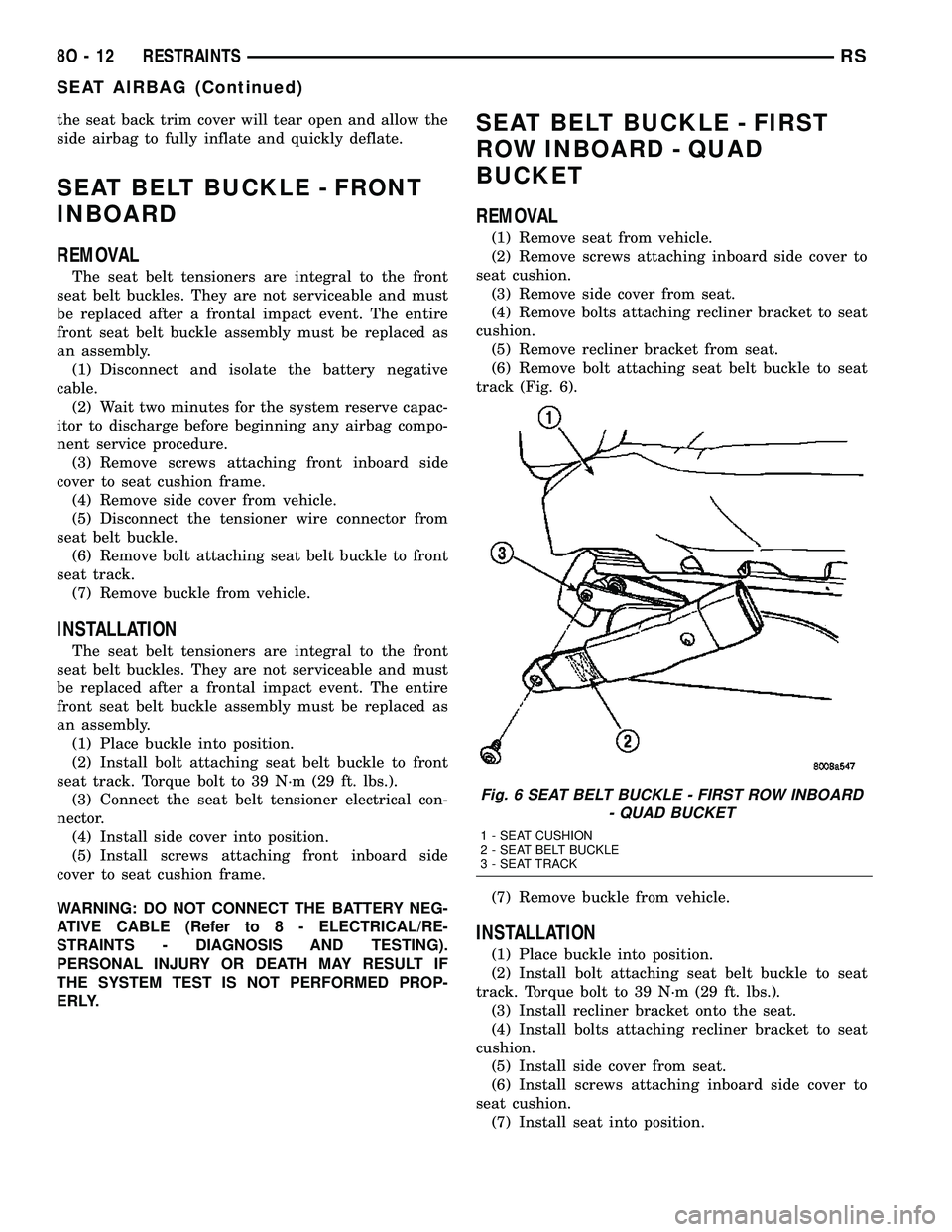
(6) Remove bolt attaching seat belt buckle to seat
track (Fig. 6).
(7) Remove buckle from vehicle.
INSTALLATION
(1) Place buckle into position.
(2) Install bolt attaching seat belt buckle to seat
track. Torque bolt to 39 N´m (29 ft. lbs.).
(3) Install recliner bracket onto the seat.
(4) Install bolts attaching recliner bracket to seat
cushion.
(5) Install side cover from seat.
(6) Install screws attaching inboard side cover to
seat cushion.
(7) Install seat into position.
Fig. 6 SEAT BELT BUCKLE - FIRST ROW INBOARD
- QUAD BUCKET
1 - SEAT CUSHION
2 - SEAT BELT BUCKLE
3 - SEAT TRACK
8O - 12 RESTRAINTSRS
SEAT AIRBAG (Continued)
Page 668 of 2585
SEAT BELT BUCKLE - FIRST
ROW - BENCH
REMOVAL
(1) Remove seat from vehicle.
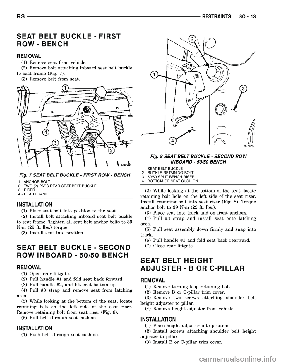
(2) Remove bolt attaching inboard seat belt buckle
to seat frame (Fig. 7).
(3) Remove belt from seat.
INSTALLATION
(1) Place seat belt into position to the seat.
(2) Install bolt attaching inboard seat belt buckle
to seat frame. Tighten all seat belt anchor bolts to 39
N´m (29 ft. lbs.) torque.
(3) Install seat into position.
SEAT BELT BUCKLE - SECOND
ROW INBOARD - 50/50 BENCH
REMOVAL
(1) Open rear liftgate.
(2) Pull handle #1 and fold seat back forward.
(3) Pull handle #2, and lift seat bottom up.
(4) Pull #3 strap and remove seat from latching
area.
(5) While looking at the bottom of the seat, locate
retaining bolt on the left side of the seat riser.
Remove retaining bolt from seat riser (Fig. 8).
(6) Pull belt through seat cushion.
INSTALLATION
(1) Push belt through seat cushion.(2) While looking at the bottom of the seat, locate
retaining bolt hole on the left side of the seat riser.
Install retaining bolt into seat riser (Fig. 8). Torque
anchor bolt to 39 N´m (29 ft. lbs.).
(3) Place seat into track and on front anchors.
(4) Pull #3 strap and install seat onto latching
area.
(5) Pull seat assembly down firmly and snap into
track.
(6) Pull handle #1 and fold seat back rearward.
(7) Close rear liftgate.
SEAT BELT HEIGHT
ADJUSTER-BORC-PILLAR
REMOVAL
(1) Remove turning loop retaining bolt.
(2) Remove B or C-pillar trim cover.
(3) Remove two screws attaching shoulder belt
height adjuster to pillar.
(4) Remove height adjuster from vehicle.
INSTALLATION
(1) Place height adjuster into position.
(2) Install screws attaching shoulder belt height
adjuster to pillar.
(3) Install B or C-pillar trim cover.
Fig. 7 SEAT BELT BUCKLE - FIRST ROW - BENCH
1 - ANCHOR BOLT
2 - TWO (2) PASS REAR SEAT BELT BUCKLE
3 - RISER
4 - REAR FRAME
Fig. 8 SEAT BELT BUCKLE - SECOND ROW
INBOARD - 50/50 BENCH
1 - SEAT BELT BUCKLE
2 - BUCKLE RETAINING BOLT
3 - 50/50 SPLIT BENCH RISER
4 - BOTTOM OF SEAT CUSHION
RSRESTRAINTS8O-13
Page 669 of 2585

(4) Install turning loop to height adjuster. Torque
anchor bolt to 39 N´m (29 ft. lbs.).
SEAT BELT HEIGHT
ADJUSTER KNOB
REMOVAL
(1) Disengage clips attaching clam shell cover to
seat belt turning loop and open cover.
(2) Using a trim tool (special tool #C-4755), gently
pry knob from seat belt height adjuster.
INSTALLATION
(1) Place seat belt height adjuster knob in position
on height adjuster.
(2) Firmly push knob on until retainers engage.
(3) Reinstall turning loop clam shell cover.
(4) Verify seat belt operation. Make sure it moves
through loop without binding.
SEAT BELT & RETRACTOR -
OUTBOARD - FRONT
REMOVAL
(1) Open door.
(2) Move seat all the way forward.
(3) Open hood.
(4) Disconnect and isolate the negative battery
cable.
(5) Remove shoulder harness height adjuster knob
by pulling it straight away from adjuster.
(6) Remove cover from seat belt turning loop.
(7) Remove bolt attaching turning loop to shoulder
belt height adjuster.
(8) Remove upper B-pillar trim cover.
(9) Remove the lower seat belt anchor bolt.
(10) Remove front door sill plate.
(11) Remove sliding door sill plate.
(12) Remove lower B-pillar trim cover.
(13) Disconnect the seat belt retractor electrical
connector.
(14) Remove seat belt retractor attaching bolt.
(15) Remove the seat belt and retractor from vehi-
cle.
INSTALLATION
Inspect the condition of the shoulder belt and lap
belt. Replace any belt that is cut, frayed, torn, or
damaged in any way. Also, replace the shoulder belt
if the retractor is either damaged or inoperative.
(1) Place seat belt and retractor into position.
(2) Install bolt attaching seat belt retractor to
B-pillar. Torque bolt to 39 N´m (29 ft. lbs.).(3) Connect the seat belt retractor electrical con-
nector.
(4) Install the lower B-pillar trim cover.
(5) Install the sliding door sill plate.
(6) Install the front door sill plate.
(7) Install the lower seat belt anchor bolt. Torque
bolt to 39 N´m (29 ft. lbs.).
(8) Install the upper B-pillar trim cover.
(9) Install the bolt attaching turning loop to shoul-
der belt height adjuster. Torque bolt to 39 N´m (29 ft.
lbs.).
(10) Install the cover to the seat belt turning loop.
(11) Install the shoulder harness height adjuster
knob by pushing it straight onto the adjuster.
(12) Connect the battery negative cable.
(13) Verify vehicle and system operation.
(14) Move seat back to approximate customer posi-
tion.
(15) Close hood and door.
SEAT BELT & RETRACTOR -
FIRST ROW - OUTBOARD
REMOVAL
(1) Remove first and second row seats.
(2) Remove first row seat belt lower anchor bolt.
(3) Remove first row seat belt upper turning loop
anchor bolt.
(4) Remove liftgate sill plate.
(5) Remove upper liftgate trim.
(6) Remove second seat lower anchor bolt.
(7) Remove second seat upper turning loop anchor
bolt.
(8) Remove D-pillar trim cover.
(9) Disconnect speaker connector. The left side has
the speaker mounted in the D-pillar trim cover and
the right side will have the speaker mounted in the
rear of the quarter trim panel, but the connector is
accessible from the rear after the D-pillar trim is
removed.
(10) Remove quarter trim bolster.
(11) Remove quarter trim panel screws.
(12) Remove quarter trim panel.
(13) Remove first row seat belt and retractor
retaining bolt.
(14) Remove first row seat belt and retractor from
vehicle.
INSTALLATION
(1) Install first row seat belt and retractor. Torque
bolt to 39 N´m (29 ft. lbs.).
(2) Install quarter trim panel.
(3) Install quarter trim panel screws.
(4) Install quarter trim bolster.
8O - 14 RESTRAINTSRS
SEAT BELT HEIGHT ADJUSTER-BORC-PILLAR (Continued)
Page 670 of 2585
(5) Connect speaker connector. The left side has
the speaker mounted in the D-pillar trim cover and
the right side will have the speaker mounted in the
rear of the quarter trim panel, but the connector is
accessible from the rear after the D-pillar trim is
removed.
(6) Install D-pillar trim cover.
(7) Install second seat belt lower anchor bolt.
Torque bolt to 39 N´m (29 ft. lbs.).
(8) Install second seat belt upper turning loop
anchor bolt. Torque bolt to 39 N´m (29 ft. lbs.).
(9) Install upper liftgate trim.
(10) Install liftgate sill plate.
(11) Install first row seat belt upper turning loop
anchor bolt. Torque bolt to 39 N´m (29 ft. lbs.).
(12) Install first row seat belt lower anchor bolt.
Torque bolt to 39 N´m (29 ft. lbs.).
(13) Install first and second row seats.
SEAT BELT BUCKLE - SECOND
ROW - THREE PASSENGER
BENCH
REMOVAL
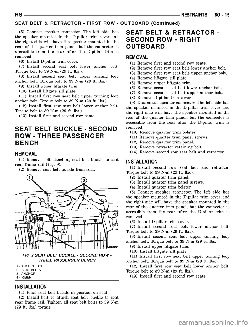
(1) Remove bolt attaching seat belt buckle to seat
rear frame rail (Fig. 9).
(2) Remove seat belt buckle from seat.
INSTALLATION
(1) Place seat belt buckle in position on seat.
(2) Install bolt to attach seat belt buckle to seat
rear frame rail. Tighten all seat belt bolts to 39 N´m
(29 ft. lbs.) torque.
SEAT BELT & RETRACTOR -
SECOND ROW - RIGHT
OUTBOARD
REMOVAL
(1) Remove first and second row seats.
(2) Remove first row seat belt lower anchor bolt.
(3) Remove first row seat belt upper anchor bolt.
(4) Remove liftgate sill plate.
(5) Remove upper liftgate trim.
(6) Remove second seat belt lower anchor bolt.
(7) Remove second seat belt upper anchor bolt.
(8) Remove D-pillar trim cover.
(9) Disconnect speaker connector. The left side has
the speaker mounted in the D-pillar trim cover and
the right side will have the speaker mounted in the
rear of the quarter trim panel, but the connector is
accessible from the rear after the D-pillar trim is
removed.
(10) Remove quarter trim bolster.
(11) Remove quarter trim panel screws.
(12) Remove quarter trim panel.
(13) Remove retractor retaining bolt.
(14) Remove second row seat belt and retractor.
INSTALLATION
(1) Install second row seat belt and retractor.
Torque bolt to 39 N´m (29 ft. lbs.).
(2) Install quarter trim panel.
(3) Install quarter trim panel screws.
(4) Install quarter trim bolster.
(5) Connect speaker connector. The left side has
the speaker mounted in the D-pillar trim cover and
the right side will have the speaker mounted in the
rear of the quarter trim panel, but the connector is
accessible from the rear after the D-pillar trim is
removed.
(6) Install D-pillar trim cover.
(7) Install second seat belt lower anchor bolt.
Torque bolt to 39 N´m (29 ft. lbs.).
(8) Install second seat belt upper turning loop
anchor bolt. Torque bolt to 39 N´m (29 ft. lbs.).
(9) Install upper liftgate trim.
(10) Install liftgate sill plate.
(11) Install first row seat belt upper turning loop
anchor bolt. Torque bolt to 39 N´m (29 ft. lbs.).
(12) Install first row seat belt lower anchor bolt.
Torque bolt to 39 N´m (29 ft. lbs.).
(13) Install first and second row seats.
Fig. 9 SEAT BELT BUCKLE - SECOND ROW -
THREE PASSENGER BENCH
1 - ANCHOR BOLT
2 - SEAT BELTS
3 - ANCHOR
4 - RISER
RSRESTRAINTS8O-15
SEAT BELT & RETRACTOR - FIRST ROW - OUTBOARD (Continued)
Page 671 of 2585
SEAT BELT & RETRACTOR -
SECOND ROW - RIGHT OUTBOARD
WITH REAR HVAC - LWB
REMOVAL
(1) Remove first and second row seats.
(2) Remove first row seat belt lower anchor bolt.
(3) Remove first row seat belt upper anchor bolt.
(4) Remove liftgate sill plate.
(5) Remove upper liftgate trim.
(6) Remove second seat belt lower anchor bolt.
(7) Remove second seat belt upper anchor bolt.
(8) Remove D-pillar trim cover.
(9) Disconnect speaker connector. The left side has
the speaker mounted in the D-pillar trim cover and
the right side will have the speaker mounted in the
rear of the quarter trim panel, but the connector is
accessible from the rear after the D-pillar trim is
removed.
(10) Remove quarter trim bolster.
(11) Remove quarter trim panel screws.
(12) Remove quarter trim panel.
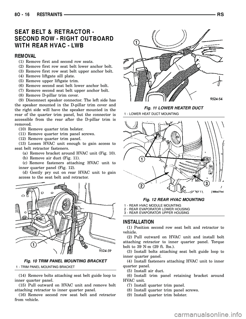
(13) Loosen HVAC unit enough to gain access to
seat belt retractor fasteners.
(a) Remove bracket around HVAC unit (Fig. 10).
(b) Remove air duct (Fig. 11).
(c) Remove fasteners attaching HVAC unit to
inner quarter panel (Fig. 12).
(d) Gently pry out on rear HVAC unit to gain
access to the seat belt and retractor.
(14) Remove bolts attaching seat belt guide loop to
inner quarter panel.
(15) Pull outward on HVAC unit and remove bolt
attaching retractor to inner quarter panel.
(16) Remove second row seat belt and retractor
from vehicle.
INSTALLATION
(1) Position second row seat belt and retractor to
vehicle.
(2) Pull outward on HVAC unit and install bolt
attaching retractor to inner quarter panel. Torque
bolt to 39 N´m (29 ft. lbs.).
(3) Install bolts attaching seat belt guide loop to
inner quarter panel.
(4) Install fasteners attaching HVAC unit to inner
quarter panel.
(5) Install air duct.
(6) Install trim panel retaining bracket around
HVAC unit.
(7) Install quarter trim panel.
(8) Install quarter trim panel screws.
(9) Install quarter trim bolster.
Fig. 10 TRIM PANEL MOUNTING BRACKET
1 - TRIM PANEL MOUNTING BRACKET
Fig. 11 LOWER HEATER DUCT
1 - LOWER HEAT DUCT MOUNTING
Fig. 12 REAR HVAC MOUNTING
1 - REAR HVAC MODULE MOUNTING
2 - REAR EVAPORATOR LOWER HOUSING
3 - REAR EVAPORATOR UPPER HOUSING
8O - 16 RESTRAINTSRS
Page 672 of 2585
(10) Connect speaker connector. The left side has
the speaker mounted in the D-pillar trim cover and
the right side will have the speaker mounted in the
rear of the quarter trim panel, but the connector is
accessible from the rear after the D-pillar trim is
removed.
(11) Install D-pillar trim cover.
(12) Install second seat belt lower anchor bolt.
Torque bolt to 39 N´m (29 ft. lbs.).
(13) Install second seat belt upper turning loop
anchor bolt. Torque bolt to 39 N´m (29 ft. lbs.).
(14) Install upper liftgate trim.
(15) Install liftgate sill plate.
(16) Install first row seat belt upper turning loop
anchor bolt. Torque bolt to 39 N´m (29 ft. lbs.).
(17) Install first row seat belt lower anchor bolt.
Torque bolt to 39 N´m (29 ft. lbs.).
(18) Install first and second row seats.
SEAT BELT & RETRACTOR -
SECOND ROW - LEFT
OUTBOARD
REMOVAL
(1) Remove first and second row seats.
(2) Remove first row seat belt lower anchor bolt.
(3) Remove first row seat belt upper anchor bolt.
(4) Remove liftgate sill plate.
(5) Remove upper liftgate trim.
(6) Remove second seat belt lower anchor bolt.
(7) Remove second seat belt upper anchor bolt.
(8) Remove D-pillar trim cover.
(9) Disconnect speaker connector. The left side has
the speaker mounted in the D-pillar trim cover and
the right side will have the speaker mounted in the
rear of the quarter trim panel, but the connector is
accessible from the rear after the D-pillar trim is
removed.
(10) Remove quarter trim bolster.
(11) Remove quarter trim panel screws.
(12) Remove quarter trim panel.
(13) Remove retractor retaining bolt.
(14) Remove second row seat belt and retractor
from vehicle.
INSTALLATION
(1) Install second row seat belt and retractor.
Torque bolt to 39 N´m (29 ft. lbs.).
(2) Install quarter trim panel.
(3) Install quarter trim panel screws.
(4) Install quarter trim bolster.
(5) Connect speaker connector. The left side has
the speaker mounted in the D-pillar trim cover andthe right side will have the speaker mounted in the
rear of the quarter trim panel, but the connector is
accessible from the rear after the D-pillar trim is
removed.
(6) Install D-pillar trim cover.
(7) Install second seat belt lower anchor bolt.
Torque bolt to 39 N´m (29 ft. lbs.).
(8) Install second seat belt upper turning loop
anchor bolt. Torque bolt to 39 N´m (29 ft. lbs.).
(9) Install upper liftgate trim.
(10) Install liftgate sill plate.
(11) Install first row seat belt upper turning loop
anchor bolt. Torque bolt to 39 N´m (29 ft. lbs.).
(12) Install first row seat belt lower anchor bolt.
Torque bolt to 39 N´m (29 ft. lbs.).
(13) Install first and second row seats.
SEAT BELT TENSIONER
DESCRIPTION
The seat belt system incorporates Seat Belt Ten-
sioners. The tensioner is designed to hold the occu-
pant in their respective seat by retracting the seat
belt up to four inches. They are integral to the front
seat belt buckles and cannot be serviced. If found
defective they must be replaced. After an airbag
deployment, the tensioner must be replaced.
OPERATION
At the onset of an impact event, each tensioner
uses a pyrotechnic device which is triggered simulta-
neously with the airbags to rapidly retract the seat
belts. With the slack removed, the occupant's forward
motion in an impact will be reduced as will the like-
lihood of contacting interior components. After an
impact that deploys the airbags, the seat belt ten-
sioner assembly must be replaced.
The Occupant Restraint Controller (ORC) monitors
the seat belt tensioner circuit resistance and reports
active and stored Diagnostic Trouble Codes (DTC's) if
any problem is found.
Once a vehicle has been in an accident, the ten-
sioner must be replaced along with any deployed air-
bags and broken or damaged parts. Refer to the
proper Body Diagnostic Procedures manual for diag-
nosis and testing.
WARNING: WHEN THE FRONT AIRBAG IS
DEPLOYED, THE TENSIONER WILL HAVE
DEPLOYED ALSO AND SHOULD BE REPLACED.
FAILURE TO DO SO COULD RESULT IN OCCUPANT
PERSONAL INJURY OR DEATH.
RSRESTRAINTS8O-17
SEAT BELT & RETRACTOR - SECOND ROW - RIGHT OUTBOARD WITH REAR HVAC - LWB (Continued)
Page 674 of 2585
SPEED CONTROL
TABLE OF CONTENTS
page page
SPEED CONTROL
DESCRIPTION..........................1
OPERATION
OPERATION..........................1
OPERATION - INTERACTIVE SPEED
CONTROL (4 Speed EATX Only)...........2
DIAGNOSIS AND TESTING - ROAD TEST.....3
SPECIFICATIONS - TORQUE...............3
CABLE
DESCRIPTION..........................4
OPERATION............................4
REMOVAL.............................4
INSTALLATION..........................4
SERVO
DESCRIPTION..........................4OPERATION............................4
REMOVAL.............................5
INSTALLATION..........................5
SWITCH
DESCRIPTION..........................6
OPERATION............................6
REMOVAL.............................6
INSTALLATION..........................6
VACUUM RESERVOIR
DESCRIPTION..........................6
OPERATION............................6
REMOVAL.............................6
INSTALLATION..........................6
SPEED CONTROL
DESCRIPTION
The speed control system is electronically con-
trolled and vacuum operated. The electronic control
is integrated into the Powertrain Control Module.
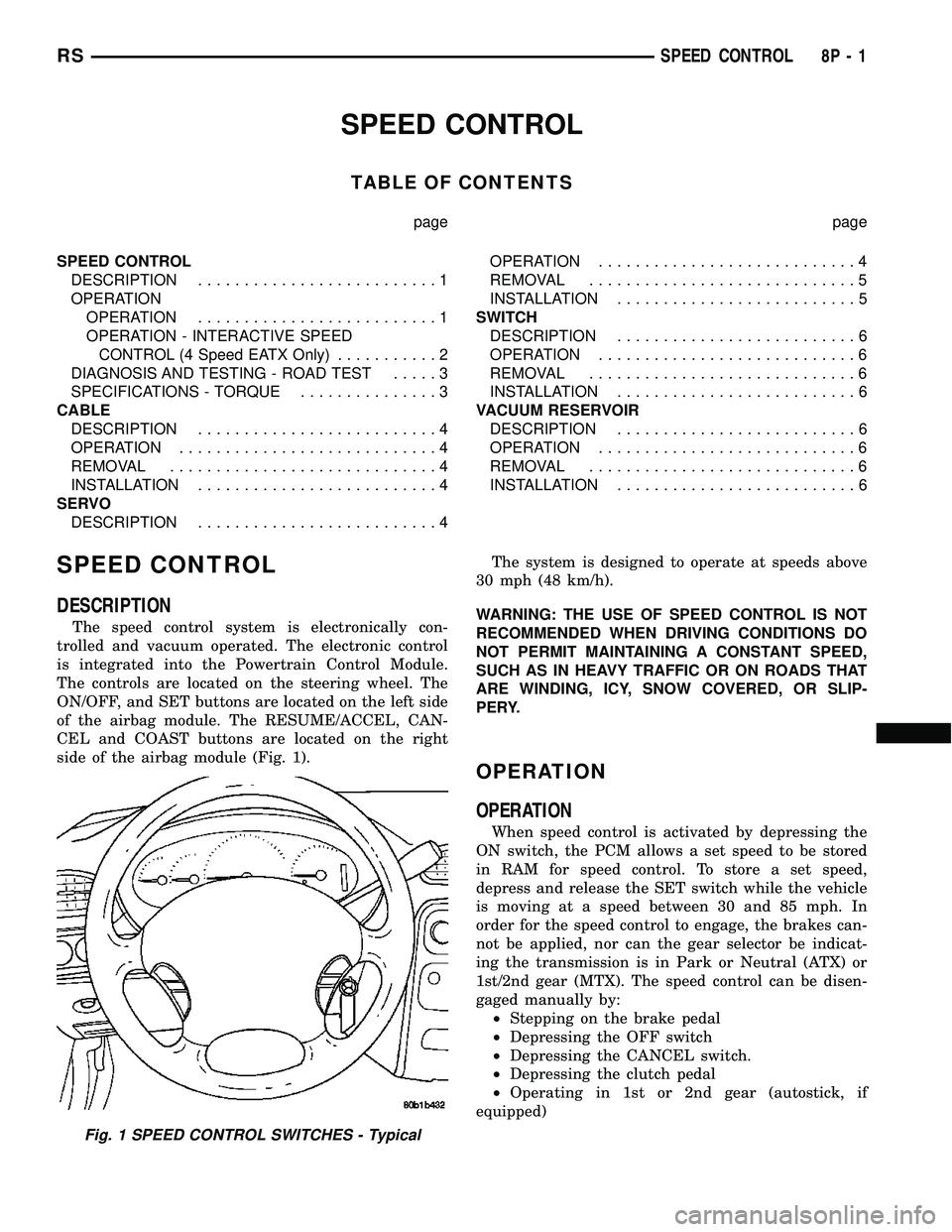
The controls are located on the steering wheel. The
ON/OFF, and SET buttons are located on the left side
of the airbag module. The RESUME/ACCEL, CAN-
CEL and COAST buttons are located on the right
side of the airbag module (Fig. 1).The system is designed to operate at speeds above
30 mph (48 km/h).
WARNING: THE USE OF SPEED CONTROL IS NOT
RECOMMENDED WHEN DRIVING CONDITIONS DO
NOT PERMIT MAINTAINING A CONSTANT SPEED,
SUCH AS IN HEAVY TRAFFIC OR ON ROADS THAT
ARE WINDING, ICY, SNOW COVERED, OR SLIP-
PERY.
OPERATION
OPERATION
When speed control is activated by depressing the
ON switch, the PCM allows a set speed to be stored
in RAM for speed control. To store a set speed,
depress and release the SET switch while the vehicle
is moving at a speed between 30 and 85 mph. In
order for the speed control to engage, the brakes can-
not be applied, nor can the gear selector be indicat-
ing the transmission is in Park or Neutral (ATX) or
1st/2nd gear (MTX). The speed control can be disen-
gaged manually by:
²Stepping on the brake pedal
²Depressing the OFF switch
²Depressing the CANCEL switch.
²Depressing the clutch pedal
²Operating in 1st or 2nd gear (autostick, if
equipped)
Fig. 1 SPEED CONTROL SWITCHES - Typical
RSSPEED CONTROL8P-1
Page 676 of 2585
AUTOMATIC SPEED CONTROL OVERSPEED
REDUCTION
DESCRIPTION
Transmission control software includes an auto-
matic speed control overspeed reduction feature. This
maintains vehicle speed at the selected set point
when descending a grade.
OPERATION
The TCM (on SBEC vehicles) (PCM on NGC vehi-
cles) first senses that the speed control is set. If the
set speed is exceeded by more than 4 mph (6.5
km/hr) and the throttle is closed, the TCM (on SBEC
vehicles) (PCM on NGC vehicles) causes the trans-
axle to downshift to THIRD gear. After downshifting,
the automatic speed control resumes normal opera-
tion. To ensure that an upshift is appropriate after
the set speed is reached, the TCM (on SBEC vehi-
cles) (PCM on NGC vehicles) waits until the speed
control system opens the throttle at least 6 degrees
before upshifting to OVERDRIVE again.
If the driver applies the brakes, canceling auto-
matic speed control operation with the transaxle still
in THIRD gear, the TCM (on SBEC vehicles) (PCM
on NGC vehicles) maintains this gear until the driver
opens the throttle at least 6 degrees to avoid an inap-
propriate upshift. The upshift is also delayed for 2.5
seconds after reaching the 6 degrees throttle opening
in anticipation that the driver might open the throt-
tle enough to require THIRD gear. This will avoid
unnecessary and disturbing transmission cycling. If
the automatic speed control RESUME feature is used
after braking, the upshift is delayed until the set
speed is achieved to reduce cycling and provide bet-
ter response.
DIAGNOSIS AND TESTING - ROAD TEST
Perform a vehicle road test to verify reports of
speed control system malfunction. The road test
should include attention to the speedometer. Speed-
ometer operation should be smooth and without flut-
ter at all speeds.
Flutter in the speedometer indicates a problem
which might cause surging in the speed control sys-
tem. The cause of any speedometer problems should
be corrected before proceeding. Refer to the Instru-
ment Cluster for speedometer diagnosis.
If a road test verifies an inoperative system, and
the speedometer operates properly, check for:
²A Diagnostic Trouble Code (DTC). If a DTC
exists, conduct tests per the Powertrain Diagnostic
Procedures manual.
²A misadjusted brake (stop) lamp switch. This
could also cause an intermittent problem.
²Loose or corroded electrical connections at the
servo. Corrosion should be removed from electrical
terminals and a light coating of Mopar Multipurpose
Grease, or equivalent, applied.
²Leaking vacuum reservoir.
²Loose or leaking vacuum hoses or connections.
²Defective one-way vacuum check valve.
²Secure attachment at both ends of the speed
control servo cable.
²Smooth operation of throttle linkage and throttle
body air valve.
²Conduct electrical test at PCM.
²Failed speed control servo. Do the servo vacuum
test.
CAUTION: When test probing for voltage or conti-
nuity at electrical connectors, care must be taken
not to damage connector, terminals or seals. If
these components are damaged, intermittent or
complete system failure may occur.
SPECIFICATIONS - TORQUE
DESCRIPTION N´m Ft. Lbs. In. Lbs.
Servo Mounting Bracket
Nuts14 10.3 123.9
Servo Mounting Bracket
Bolts14 10.3 123.9
Servo Mounting Nuts 6.7 60
RSSPEED CONTROL8P-3
SPEED CONTROL (Continued)
Page 695 of 2585

FRONT WASHER PUMP
MOTOR
REMOVAL
(1) Disconnect and isolate the battery negative
cable.
(2) Remove the engine fresh air housing inside the
engine compartment (Refer to 9 - ENGINE/AIR
INTAKE SYSTEM/AIR CLEANER HOUSING -
REMOVAL).
(3) Disconnect the washer hose at the in-line con-
nector forward of the cowl grille so that the in-line
connector remains with the washer hose from the
fresh air plenum.
(4) Disconnect the washer hose from the hose clip
located on the front fender side shield.
(5) Remove the filler tube screw.
(6) Hoist and support vehicle on hoist or jack
stands.
(7) Remove the right front wheel and tire assembly
(Refer to 22 - TIRES/WHEELS - REMOVAL).
(8) Disconnect the left right front wheelhouse
splash shield and move aside (Refer to 23 - BODY/
EXTERIOR/WHEELHOUSE SPLASH SHIELD -
REMOVAL).
(9) Drain washer fluid from the reservoir and into
a suitable clean container. This can be done by dis-
connecting the windshield washer hose from the
front (outboard) washer pump and allowing the
washer fluid to drain into a container through a tem-
porary jumper hose connected to the front washer
pump.
(10) Disconnect the electrical body harness connec-
tors to the washer pump motors and the fluid level
sensor. Slide the red lock on the connector to the
release position, then, depress the black tab and pull
the connector off the pump or sensor.
(11) Remove the two reservoir mounting screws.
(12) Disconnect the reservoir from the body mount
by raising the reservoir upward slightly and then
down so that the reservoir filler neck and front
washer hose pull through the opening in the front
fender side shield.
(13) Remove pump from reservoir by pulling pump
upper retention tab away from reservoir cavity and
then lifting pump up from mounting grommet. Do
not damage reservoir/pump sealing surface or punc-
ture reservoir during removal.
(14) Remove pump grommet and discard.
INSTALLATION
(1) Use new grommet when installing a new pump
assembly.
(2) Assure pump upper retention tab is pressed
into reservoir slot and that pump is rotated flatagainst the reservoir and that pump connector is fac-
ing up in the fully seated position. Assure the pump
is aligned to and fully seated in the reservoir cavity.
(3) Push filler neck and front washer hose through
the opening in the front fender side shield. Connect
the reservoir to the body mount by lowering the res-
ervoir down.
(4) Install the two reservoir mounting screws.
Torque screws to 8.5 - 11.3 N´m (75 - 100 in. lbs.).
(5) Connect the electrical body harness connectors
to the washer pump motors and the fluid level sen-
sor. Slide the red lock on the connector to the closed
or locked position.
(6) Assure that washer hose is properly routed to
prevent pinching and possible inoperative washers.
(7) Connect the left right front wheelhouse splash
shield and move aside (Refer to 23 - BODY/EXTERI-
OR/WHEELHOUSE SPLASH SHIELD - INSTALLA-
TION).
(8) Install the right front wheel and tire assembly
(Refer to 22 - TIRES/WHEELS - INSTALLATION).
(9) lower vehicle from hoist or jack stands.
(10) Install the filler tube screw. Torque screw to
8.5 - 11.3 N´m (75 - 100 in. lbs.).
(11) Connect the washer hose to the hose clip
located on the front fender side shield.
(12) Connect the washer hose at the in-line con-
nector forward of the cowl grille.
(13) Install the engine fresh air housing inside the
engine compartment (Refer to 9 - ENGINE/AIR
INTAKE SYSTEM/AIR CLEANER HOUSING -
INSTALLATION).
(14) Connect the battery negative cable.
(15) Verify system operation.
FRONT WIPER ARMS
STANDARD PROCEDURE - FRONT WIPER ARM
ALIGNMENT
(1) Verify wiper blade element condition and wiper
arm spring tension. Run wipers in low speed mode
while applying water to the windshield. Observe the
wiper blade that is chattering or skipping across the
windshield. If the wiper element is not rolling over
when the wiper direction reverses, align the wiper
arm. The extension bar portion of the wiper arm
must be twisted in the proper direction to allow the
wiper element to roll over when the direction
reverses.
(2) Place two small adjustable wrenches placed 50
mm (2 in.) apart on the wiper arm extension rod.
(3) Twist the extension rod slightly in the opposite
direction that the element is laying on the wind-
shield while holding the wrench closest to the pivot
stationary.
8R - 8 WIPERS/WASHERSRS