torque CHRYSLER VOYAGER 2004 Service Manual
[x] Cancel search | Manufacturer: CHRYSLER, Model Year: 2004, Model line: VOYAGER, Model: CHRYSLER VOYAGER 2004Pages: 2585, PDF Size: 62.54 MB
Page 2217 of 2585
LUMBAR SUPPORT
REMOVAL
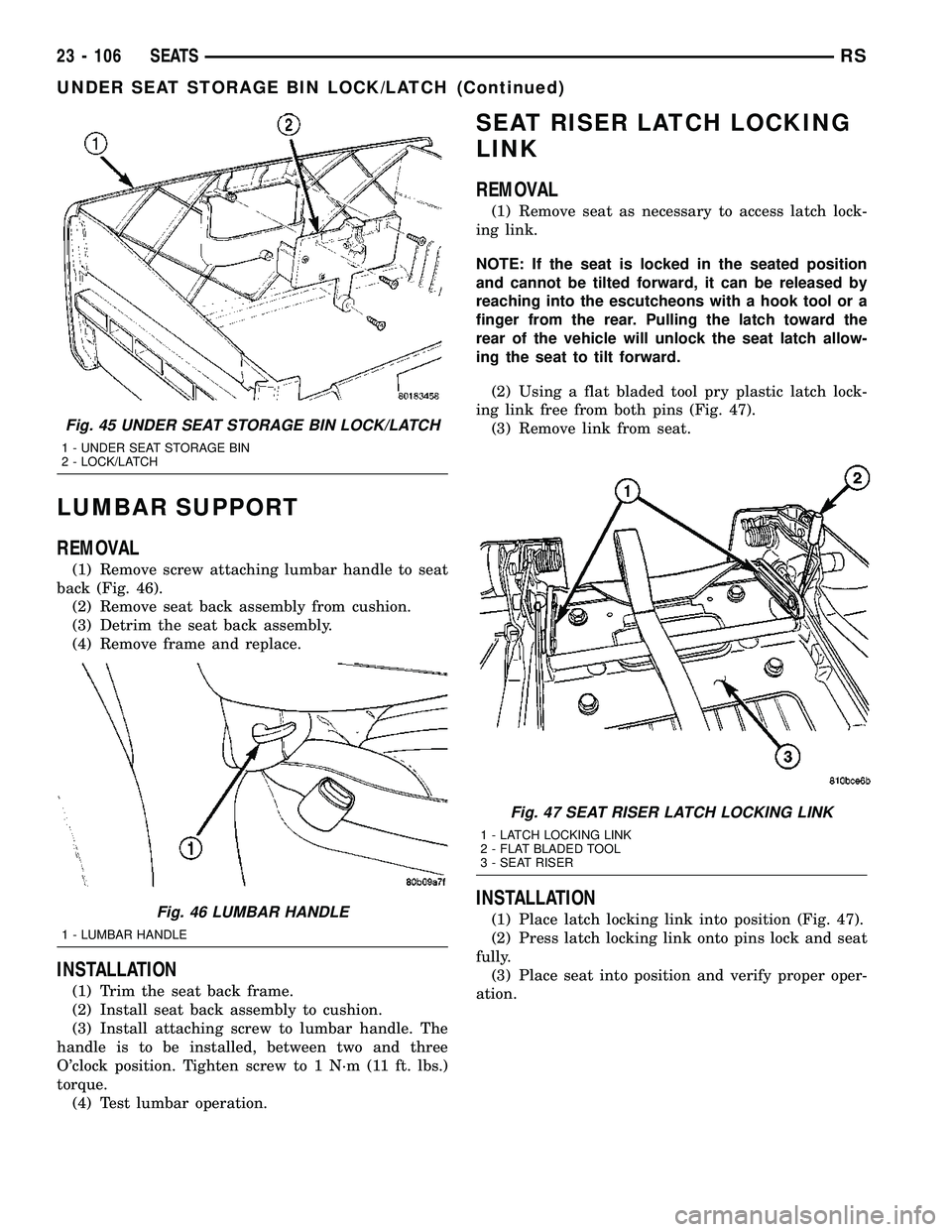
(1) Remove screw attaching lumbar handle to seat
back (Fig. 46).
(2) Remove seat back assembly from cushion.
(3) Detrim the seat back assembly.
(4) Remove frame and replace.
INSTALLATION
(1) Trim the seat back frame.
(2) Install seat back assembly to cushion.
(3) Install attaching screw to lumbar handle. The
handle is to be installed, between two and three
O'clock position. Tighten screw to 1 N´m (11 ft. lbs.)
torque.
(4) Test lumbar operation.
SEAT RISER LATCH LOCKING
LINK
REMOVAL
(1) Remove seat as necessary to access latch lock-
ing link.
NOTE: If the seat is locked in the seated position
and cannot be tilted forward, it can be released by
reaching into the escutcheons with a hook tool or a
finger from the rear. Pulling the latch toward the
rear of the vehicle will unlock the seat latch allow-
ing the seat to tilt forward.
(2) Using a flat bladed tool pry plastic latch lock-
ing link free from both pins (Fig. 47).
(3) Remove link from seat.
INSTALLATION
(1) Place latch locking link into position (Fig. 47).
(2) Press latch locking link onto pins lock and seat
fully.
(3) Place seat into position and verify proper oper-
ation.
Fig. 45 UNDER SEAT STORAGE BIN LOCK/LATCH
1 - UNDER SEAT STORAGE BIN
2 - LOCK/LATCH
Fig. 46 LUMBAR HANDLE
1 - LUMBAR HANDLE
Fig. 47 SEAT RISER LATCH LOCKING LINK
1 - LATCH LOCKING LINK
2 - FLAT BLADED TOOL
3 - SEAT RISER
23 - 106 SEATSRS
UNDER SEAT STORAGE BIN LOCK/LATCH (Continued)
Page 2221 of 2585
(16) Apply 150 mm (6 in.) lengths of 50 mm (2 in.)
masking tape spaced 250 mm (10 in.) apart to hold
molding in place until urethane cures.
(17) Install A-pillar trim panels.
(18) Install cowl cover and wipers.
(19) Install inside rear view mirror.
(20) After urethane has cured, remove tape strips
and water test windshield to verify repair.SLIDING DOOR GLASS
REMOVAL
The temperature of the vehicle should be at least
21É C (70É F) before removing the stationary quarter/
sliding door glass. Butyl sealer becomes more pliable
at high temperatures.
(1) Remove interior trim as necessary to gain
access attaching locations on back of glass.
(2) Remove nuts holding stationary glass to fence.
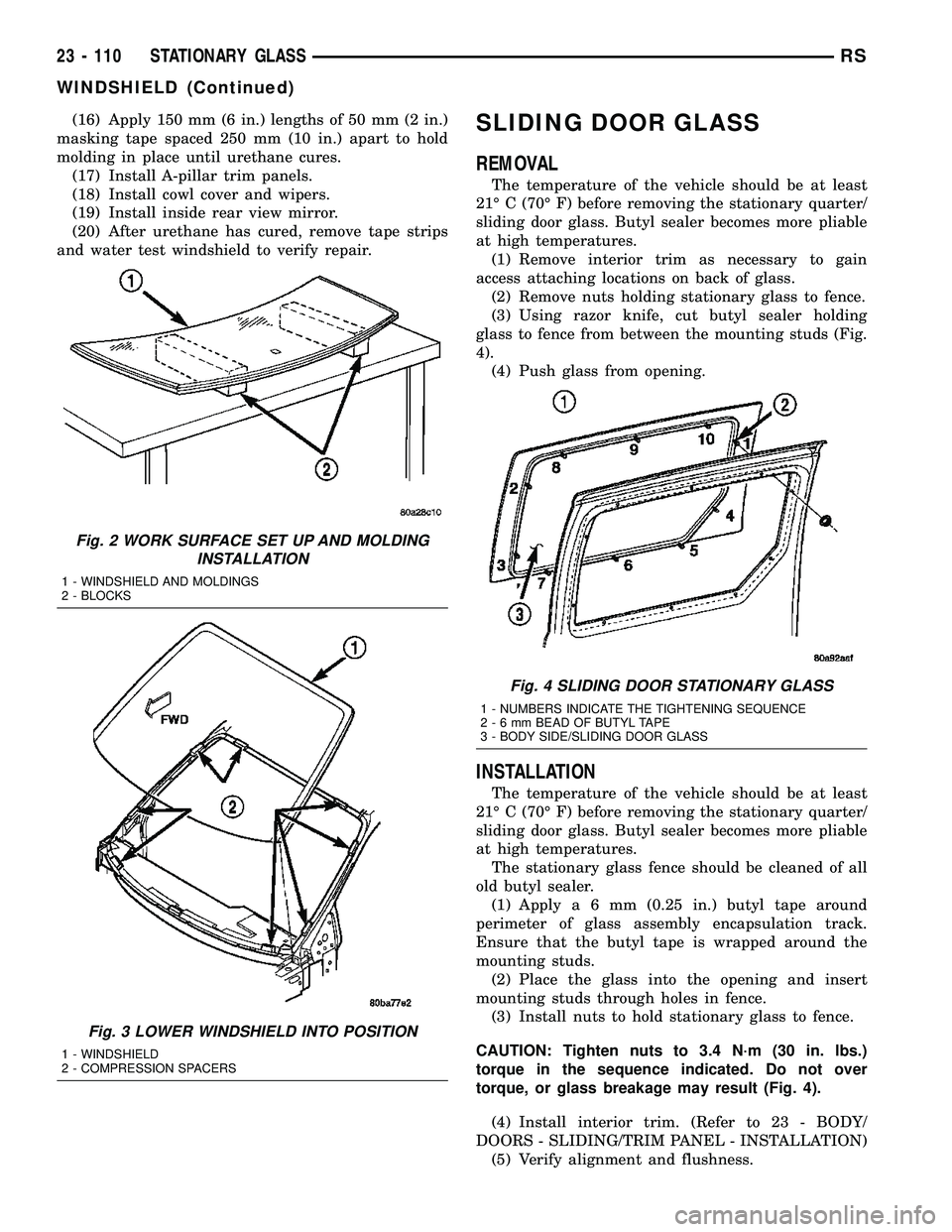
(3) Using razor knife, cut butyl sealer holding
glass to fence from between the mounting studs (Fig.
4).
(4) Push glass from opening.
INSTALLATION
The temperature of the vehicle should be at least
21É C (70É F) before removing the stationary quarter/
sliding door glass. Butyl sealer becomes more pliable
at high temperatures.
The stationary glass fence should be cleaned of all
old butyl sealer.
(1) Applya6mm(0.25 in.) butyl tape around
perimeter of glass assembly encapsulation track.
Ensure that the butyl tape is wrapped around the
mounting studs.
(2) Place the glass into the opening and insert
mounting studs through holes in fence.
(3) Install nuts to hold stationary glass to fence.
CAUTION: Tighten nuts to 3.4 N´m (30 in. lbs.)
torque in the sequence indicated. Do not over
torque, or glass breakage may result (Fig. 4).
(4) Install interior trim. (Refer to 23 - BODY/
DOORS - SLIDING/TRIM PANEL - INSTALLATION)
(5) Verify alignment and flushness.
Fig. 2 WORK SURFACE SET UP AND MOLDING
INSTALLATION
1 - WINDSHIELD AND MOLDINGS
2 - BLOCKS
Fig. 3 LOWER WINDSHIELD INTO POSITION
1 - WINDSHIELD
2 - COMPRESSION SPACERS
Fig. 4 SLIDING DOOR STATIONARY GLASS
1 - NUMBERS INDICATE THE TIGHTENING SEQUENCE
2-6mmBEAD OF BUTYL TAPE
3 - BODY SIDE/SLIDING DOOR GLASS
23 - 110 STATIONARY GLASSRS
WINDSHIELD (Continued)
Page 2231 of 2585
INSTALLATION
FRONT HOSES
(1) Connect the new drain hose to the sunroof
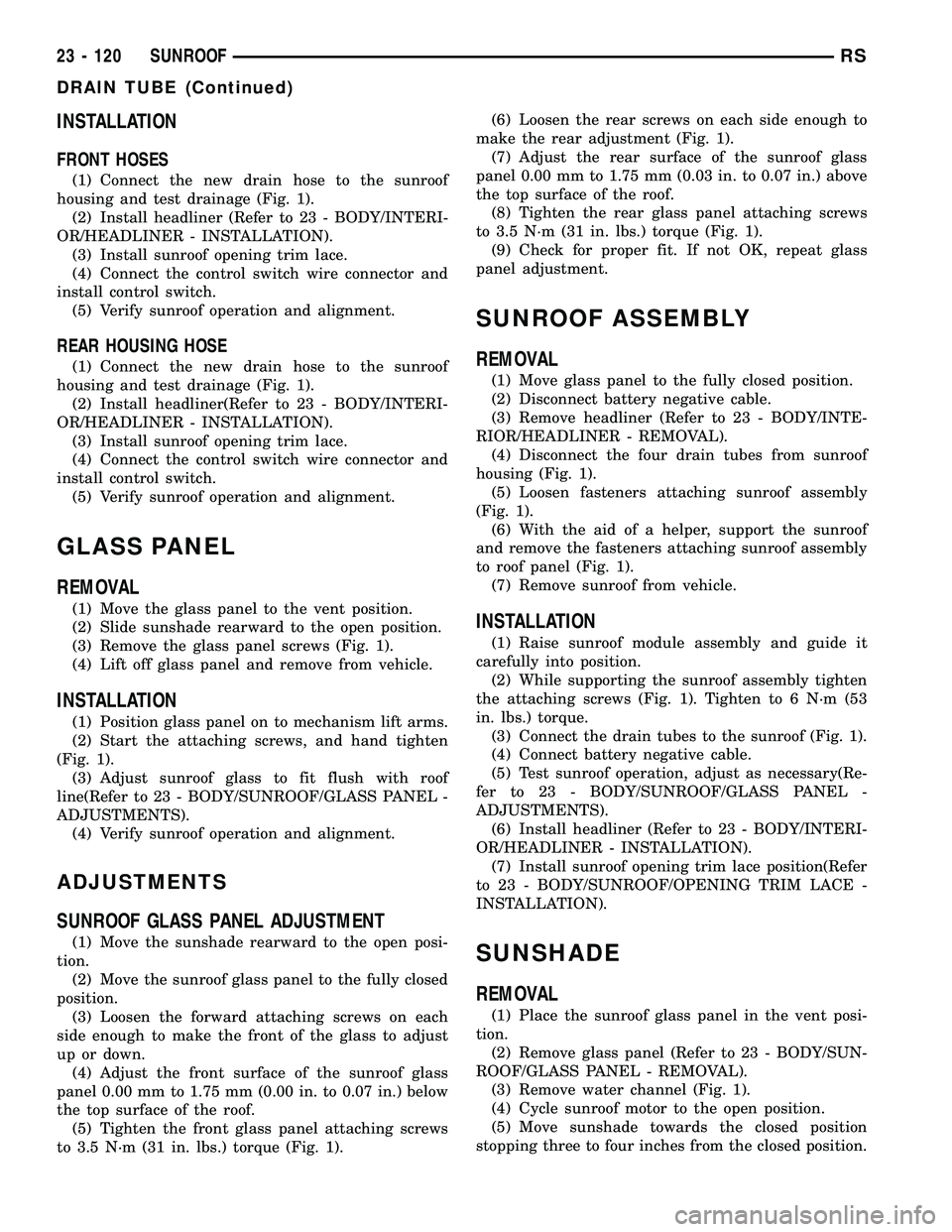
housing and test drainage (Fig. 1).
(2) Install headliner (Refer to 23 - BODY/INTERI-
OR/HEADLINER - INSTALLATION).
(3) Install sunroof opening trim lace.
(4) Connect the control switch wire connector and
install control switch.
(5) Verify sunroof operation and alignment.
REAR HOUSING HOSE
(1) Connect the new drain hose to the sunroof
housing and test drainage (Fig. 1).
(2) Install headliner(Refer to 23 - BODY/INTERI-
OR/HEADLINER - INSTALLATION).
(3) Install sunroof opening trim lace.
(4) Connect the control switch wire connector and
install control switch.
(5) Verify sunroof operation and alignment.
GLASS PANEL
REMOVAL
(1) Move the glass panel to the vent position.
(2) Slide sunshade rearward to the open position.
(3) Remove the glass panel screws (Fig. 1).
(4) Lift off glass panel and remove from vehicle.
INSTALLATION
(1) Position glass panel on to mechanism lift arms.
(2) Start the attaching screws, and hand tighten
(Fig. 1).
(3) Adjust sunroof glass to fit flush with roof
line(Refer to 23 - BODY/SUNROOF/GLASS PANEL -
ADJUSTMENTS).
(4) Verify sunroof operation and alignment.
ADJUSTMENTS
SUNROOF GLASS PANEL ADJUSTMENT
(1) Move the sunshade rearward to the open posi-
tion.
(2) Move the sunroof glass panel to the fully closed
position.
(3) Loosen the forward attaching screws on each
side enough to make the front of the glass to adjust
up or down.
(4) Adjust the front surface of the sunroof glass
panel 0.00 mm to 1.75 mm (0.00 in. to 0.07 in.) below
the top surface of the roof.
(5) Tighten the front glass panel attaching screws
to 3.5 N´m (31 in. lbs.) torque (Fig. 1).(6) Loosen the rear screws on each side enough to
make the rear adjustment (Fig. 1).
(7) Adjust the rear surface of the sunroof glass
panel 0.00 mm to 1.75 mm (0.03 in. to 0.07 in.) above
the top surface of the roof.
(8) Tighten the rear glass panel attaching screws
to 3.5 N´m (31 in. lbs.) torque (Fig. 1).
(9) Check for proper fit. If not OK, repeat glass
panel adjustment.
SUNROOF ASSEMBLY
REMOVAL
(1) Move glass panel to the fully closed position.
(2) Disconnect battery negative cable.
(3) Remove headliner (Refer to 23 - BODY/INTE-
RIOR/HEADLINER - REMOVAL).
(4) Disconnect the four drain tubes from sunroof
housing (Fig. 1).
(5) Loosen fasteners attaching sunroof assembly
(Fig. 1).
(6) With the aid of a helper, support the sunroof
and remove the fasteners attaching sunroof assembly
to roof panel (Fig. 1).
(7) Remove sunroof from vehicle.
INSTALLATION
(1) Raise sunroof module assembly and guide it
carefully into position.
(2) While supporting the sunroof assembly tighten
the attaching screws (Fig. 1). Tighten to 6 N´m (53
in. lbs.) torque.
(3) Connect the drain tubes to the sunroof (Fig. 1).
(4) Connect battery negative cable.
(5) Test sunroof operation, adjust as necessary(Re-
fer to 23 - BODY/SUNROOF/GLASS PANEL -
ADJUSTMENTS).
(6) Install headliner (Refer to 23 - BODY/INTERI-
OR/HEADLINER - INSTALLATION).
(7) Install sunroof opening trim lace position(Refer
to 23 - BODY/SUNROOF/OPENING TRIM LACE -
INSTALLATION).
SUNSHADE
REMOVAL
(1) Place the sunroof glass panel in the vent posi-
tion.
(2) Remove glass panel (Refer to 23 - BODY/SUN-
ROOF/GLASS PANEL - REMOVAL).
(3) Remove water channel (Fig. 1).
(4) Cycle sunroof motor to the open position.
(5) Move sunshade towards the closed position
stopping three to four inches from the closed position.
23 - 120 SUNROOFRS
DRAIN TUBE (Continued)
Page 2406 of 2585
MECHANICAL PROBLEMS
Possible causes of insufficient heat due to mechan-
ical problems are as follows:
²Obstructed cowl air intake.
²Obstructed heater system outlets.
²Blend door not functioning properly.
TEMPERATURE CONTROL
If the heater outlet air temperature cannot be
adjusted with the temperature control knob on the
A/C-heater control panel, the following could require
service:
²Blend door binding.²Faulty blend door actuator.
²Faulty A/C-heater control.
²Faulty related wiring harness or connectors.
²Improper engine coolant temperature.
SPECIFICATIONS
A/C SYSTEM
The R-134a refrigerant system charge capacity for
this vehicle can be found on the underhood Specifica-
tion Label.
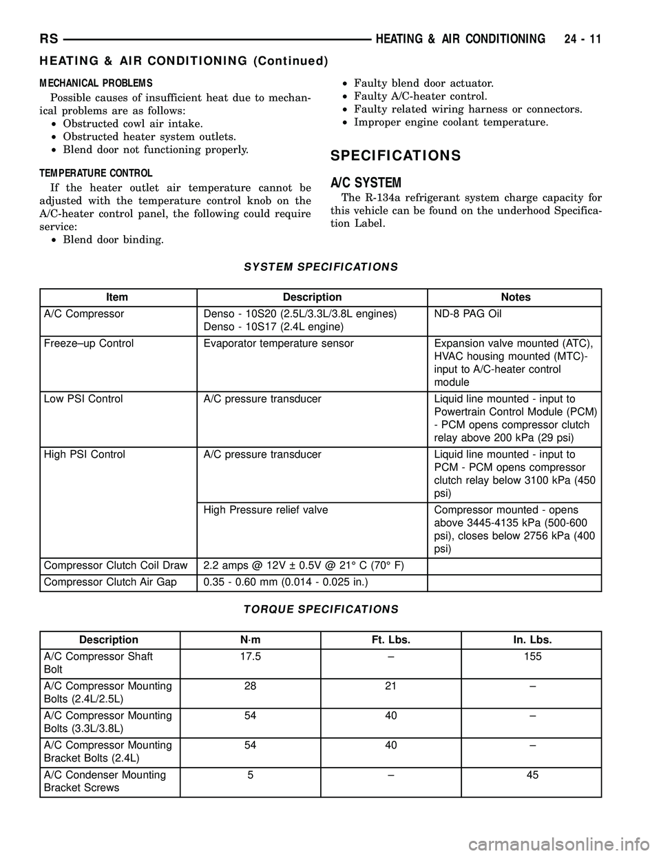
SYSTEM SPECIFICATIONS
Item Description Notes
A/C Compressor Denso - 10S20 (2.5L/3.3L/3.8L engines)
Denso - 10S17 (2.4L engine)ND-8 PAG Oil
Freeze±up Control Evaporator temperature sensor Expansion valve mounted (ATC),
HVAC housing mounted (MTC)-
input to A/C-heater control
module
Low PSI Control A/C pressure transducer Liquid line mounted - input to
Powertrain Control Module (PCM)
- PCM opens compressor clutch
relay above 200 kPa (29 psi)
High PSI Control A/C pressure transducer Liquid line mounted - input to
PCM - PCM opens compressor
clutch relay below 3100 kPa (450
psi)
High Pressure relief valve Compressor mounted - opens
above 3445-4135 kPa (500-600
psi), closes below 2756 kPa (400
psi)
Compressor Clutch Coil Draw 2.2 amps @ 12V 0.5V @ 21É C (70É F)
Compressor Clutch Air Gap 0.35 - 0.60 mm (0.014 - 0.025 in.)
TORQUE SPECIFICATIONS
Description N´m Ft. Lbs. In. Lbs.
A/C Compressor Shaft
Bolt17.5 ± 155
A/C Compressor Mounting
Bolts (2.4L/2.5L)28 21 ±
A/C Compressor Mounting
Bolts (3.3L/3.8L)54 40 ±
A/C Compressor Mounting
Bracket Bolts (2.4L)54 40 ±
A/C Condenser Mounting
Bracket Screws5±45
RSHEATING & AIR CONDITIONING24-11
HEATING & AIR CONDITIONING (Continued)
Page 2414 of 2585
COOLING/ACCESSORY DRIVE/DRIVE BELTS -
3.3L/3.8L - INSTALLATION).
(15) Lower the vehicle.
(16) Reconnect the battery negative cable.
CLUTCH BREAK-IN
After a new compressor clutch has been installed,
cycle the compressor clutch approximately twenty
times (five seconds on, then five seconds off). During
this procedure, set the A/C-heater control to the A/C
Recirculation Mode, the blower motor switch in the
highest speed position, and the engine speed at 1500
to 2000 rpm. This procedure (burnishing) will seat
the opposing friction surfaces and provide a higher
compressor clutch torque capability.
A/C COMPRESSOR CLUTCH
RELAY
DESCRIPTION
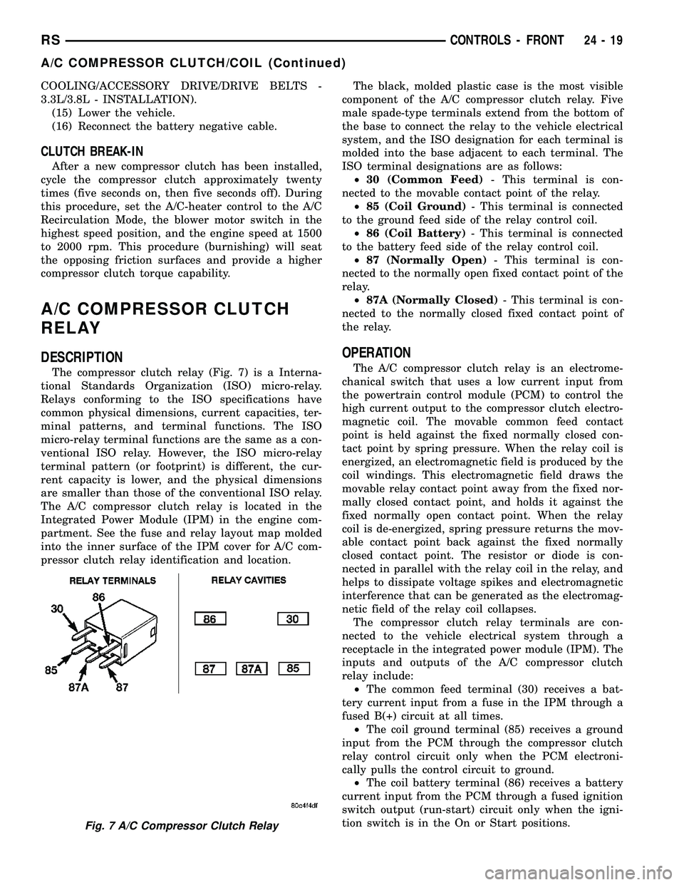
The compressor clutch relay (Fig. 7) is a Interna-
tional Standards Organization (ISO) micro-relay.
Relays conforming to the ISO specifications have
common physical dimensions, current capacities, ter-
minal patterns, and terminal functions. The ISO
micro-relay terminal functions are the same as a con-
ventional ISO relay. However, the ISO micro-relay
terminal pattern (or footprint) is different, the cur-
rent capacity is lower, and the physical dimensions
are smaller than those of the conventional ISO relay.
The A/C compressor clutch relay is located in the
Integrated Power Module (IPM) in the engine com-
partment. See the fuse and relay layout map molded
into the inner surface of the IPM cover for A/C com-
pressor clutch relay identification and location.The black, molded plastic case is the most visible
component of the A/C compressor clutch relay. Five
male spade-type terminals extend from the bottom of
the base to connect the relay to the vehicle electrical
system, and the ISO designation for each terminal is
molded into the base adjacent to each terminal. The
ISO terminal designations are as follows:
²30 (Common Feed)- This terminal is con-
nected to the movable contact point of the relay.
²85 (Coil Ground)- This terminal is connected
to the ground feed side of the relay control coil.
²86 (Coil Battery)- This terminal is connected
to the battery feed side of the relay control coil.
²87 (Normally Open)- This terminal is con-
nected to the normally open fixed contact point of the
relay.
²87A (Normally Closed)- This terminal is con-
nected to the normally closed fixed contact point of
the relay.
OPERATION
The A/C compressor clutch relay is an electrome-
chanical switch that uses a low current input from
the powertrain control module (PCM) to control the
high current output to the compressor clutch electro-
magnetic coil. The movable common feed contact
point is held against the fixed normally closed con-
tact point by spring pressure. When the relay coil is
energized, an electromagnetic field is produced by the
coil windings. This electromagnetic field draws the
movable relay contact point away from the fixed nor-
mally closed contact point, and holds it against the
fixed normally open contact point. When the relay
coil is de-energized, spring pressure returns the mov-
able contact point back against the fixed normally
closed contact point. The resistor or diode is con-
nected in parallel with the relay coil in the relay, and
helps to dissipate voltage spikes and electromagnetic
interference that can be generated as the electromag-
netic field of the relay coil collapses.
The compressor clutch relay terminals are con-
nected to the vehicle electrical system through a
receptacle in the integrated power module (IPM). The
inputs and outputs of the A/C compressor clutch
relay include:
²The common feed terminal (30) receives a bat-
tery current input from a fuse in the IPM through a
fused B(+) circuit at all times.
²The coil ground terminal (85) receives a ground
input from the PCM through the compressor clutch
relay control circuit only when the PCM electroni-
cally pulls the control circuit to ground.
²The coil battery terminal (86) receives a battery
current input from the PCM through a fused ignition
switch output (run-start) circuit only when the igni-
tion switch is in the On or Start positions.
Fig. 7 A/C Compressor Clutch Relay
RSCONTROLS - FRONT24-19
A/C COMPRESSOR CLUTCH/COIL (Continued)
Page 2522 of 2585

Effective control of exhaust emissions is achieved
by an oxygen feedback system. The most important
element of the feedback system is the O2S. The O2S
is located in the exhaust path. Once it reaches oper-
ating temperatures of 300É to 350ÉC (572 É to 662ÉF),
the sensor generates a voltage that is inversely pro-
portional to the amount of oxygen in the exhaust.
The information obtained by the sensor is used to
calculate the fuel injector pulse width. This main-
tains a 14.7 to 1 Air Fuel (A/F) ratio. At this mixture
ratio, the catalyst works best to remove hydrocarbons
(HC), carbon monoxide (CO) and nitrogen oxide
(NOx) from the exhaust.
The voltage readings taken from the O2S are very
temperature sensitive. The readings are not accurate
below 300ÉC. Heating of the O2S is done to allow the
engine controller to shift to closed loop control as
soon as possible. The heating element used to heat
the O2S must be tested to ensure that it is heating
the sensor properly.
The O2S circuit is monitored for a drop in voltage.
The sensor output is used to test the heater by iso-
lating the effect of the heater element on the O2S
output voltage from the other effects.
EGR MONITOR (if equipped)
The Powertrain Control Module (PCM) performs
an on-board diagnostic check of the EGR system.
The EGR monitor is used to test whether the EGR
system is operating within specifications. The diag-
nostic check activates only during selected engine/
driving conditions. When the conditions are met, the
EGR is turned off (solenoid energized) and the O2S
compensation control is monitored. Turning off the
EGR shifts the air fuel (A/F) ratio in the lean direc-
tion. The O2S data should indicate an increase in the
O2 concentration in the combustion chamber when
the exhaust gases are no longer recirculated. While
this test does not directly measure the operation of
the EGR system, it can be inferred from the shift in
the O2S data whether the EGR system is operating
correctly. Because the O2S is being used, the O2S
test must pass its test before the EGR test. Also
looks at EGR linear potentiometer for feedback.
MISFIRE MONITOR
Excessive engine misfire results in increased cata-
lyst temperature and causes an increase in HC emis-
sions. Severe misfires could cause catalyst damage.
To prevent catalytic convertor damage, the PCM
monitors engine misfire.
The Powertrain Control Module (PCM) monitors
for misfire during most engine operating conditions
(positive torque) by looking at changes in the crank-
shaft speed. If a misfire occurs the speed of the
crankshaft will vary more than normal.FUEL SYSTEM MONITOR
To comply with clean air regulations, vehicles are
equipped with catalytic converters. These converters
reduce the emission of hydrocarbons, oxides of nitro-
gen and carbon monoxide. The catalyst works best
when the air fuel (A/F) ratio is at or near the opti-
mum of 14.7 to 1.
The PCM is programmed to maintain the optimum
air/fuel ratio. This is done by making short term cor-
rections in the fuel injector pulse width based on the
O2S output. The programmed memory acts as a self
calibration tool that the engine controller uses to
compensate for variations in engine specifications,
sensor tolerances and engine fatigue over the life
span of the engine. By monitoring the actual air-fuel
ratio with the O2S (short term) and multiplying that
with the program long-term (adaptive) memory and
comparing that to the limit, it can be determined
whether it will pass an emissions test. If a malfunc-
tion occurs such that the PCM cannot maintain the
optimum A/F ratio, then the MIL will be illuminated.
CATALYST MONITOR
To comply with clean air regulations, vehicles are
equipped with catalytic converters. These converters
reduce the emission of hydrocarbons, oxides of nitro-
gen and carbon monoxide.
Normal vehicle miles or engine misfire can cause a
catalyst to decay. A meltdown of the ceramic core can
cause a reduction of the exhaust passage. This can
increase vehicle emissions and deteriorate engine
performance, driveability and fuel economy.
The catalyst monitor uses dual oxygen sensors
(O2S's) to monitor the efficiency of the converter. The
dual O2S's strategy is based on the fact that as a cat-
alyst deteriorates, its oxygen storage capacity and its
efficiency are both reduced. By monitoring the oxy-
gen storage capacity of a catalyst, its efficiency can
be indirectly calculated. The upstream O2S is used to
detect the amount of oxygen in the exhaust gas
before the gas enters the catalytic converter. The
PCM calculates the A/F mixture from the output of
the O2S. A low voltage indicates high oxygen content
(lean mixture). A high voltage indicates a low content
of oxygen (rich mixture).
When the upstream O2S detects a lean condition,
there is an abundance of oxygen in the exhaust gas.
A functioning converter would store this oxygen so it
can use it for the oxidation of HC and CO. As the
converter absorbs the oxygen, there will be a lack of
oxygen downstream of the converter. The output of
the downstream O2S will indicate limited activity in
this condition.
As the converter loses the ability to store oxygen,
the condition can be detected from the behavior of
the downstream O2S. When the efficiency drops, no
RSEMISSIONS CONTROL25-7
EMISSIONS CONTROL (Continued)
Page 2525 of 2585

EVAPORATIVE EMISSIONS
TABLE OF CONTENTS
page page
EVAPORATIVE EMISSIONS
OPERATION - EVAPORATION CONTROL
SYSTEM............................10
SPECIFICATIONS
TORQUE............................11
EVAP/PURGE SOLENOID
DESCRIPTION.........................12
OPERATION...........................12
REMOVAL.............................12
INSTALLATION.........................12
FUEL FILLER CAP
DESCRIPTION.........................12
OPERATION...........................12
NATURAL VAC LEAK DETECTION ASSY
REMOVAL.............................13
INSTALLATION.........................13
LEAK DETECTION PUMP
REMOVAL.............................13
INSTALLATION.........................13ORVR
OPERATION...........................14
DIAGNOSIS AND TESTING - VEHICLE DOES
NOT FILL............................16
P C V VA LV E
DESCRIPTION.........................16
OPERATION...........................16
DIAGNOSIS AND TESTING - PCV SYSTEM . . . 17
VAPOR CANISTER
DESCRIPTION.........................18
OPERATION...........................18
REMOVAL
REMOVAL...........................18
REMOVAL - WITH NVLD................19
REMOVAL - REAR EVAP CANISTER.......19
INSTALLATION
INSTALLATION.......................19
INSTALLATION - WITH NVLD............20
INSTALLATION - REAR EVAP CANISTER . . . 20
EVAPORATIVE EMISSIONS
OPERATION - EVAPORATION CONTROL
SYSTEM
The evaporation control system prevents the emis-
sion of fuel tank vapors into the atmosphere. When
fuel evaporates in the fuel tank, the vapors pass
through vent hoses or tubes to an activated carbon
filled evaporative canister. The canister temporarily
holds the vapors. The Powertrain Control Module
(PCM) allows intake manifold vacuum to draw
vapors into the combustion chambers during certain
operating conditions (Fig. 1).All engines use a proportional purge solenoid sys-
tem. The PCM controls vapor flow by operating the
purge solenoid. Refer to Proportional Purge Solenoid
in this section.
NOTE: The evaporative system uses specially man-
ufactured hoses. If they need replacement, only use
fuel resistant hose. Also the hoses must be able to
pass an Ozone compliance test.
NOTE: For more information on Onboard Refueling
Vapor Recovery (ORVR), refer to the Fuel Delivery
section.
25 - 10 EVAPORATIVE EMISSIONSRS
Page 2526 of 2585

SPECIFICATIONS
TORQUE
DESCRIPTION N´m Ft. Lbs. In. Lbs.
PCV VAlve 3.3/3.8L 6.3 55
Fig. 1 ORVR System Schematic
1 - FUEL TANK (PLASTIC)
2 - FUEL FILLER TUBE
3 - FUEL CAP (PRESSURE/RELIEF)
4 - FILL TUBE TO FUEL TANK CONNECTOR (ELASTOMERIC)
5 - TANK VENT/ROLLOVER VALVE(S)
6 - VAPOR RECIRCULATION LINE
7 - TANK VAPOR LINE
8 - VAPOR LINE TO CANISTER
9 - CHECK VALVE (N/C)
10 - CONTROL VALVE
11 - NATURAL VACUUM LEAD DETECTION (NVLD)12 - LIQUID SEPARATOR (IF EQUIPPED)
13 - ENGINE WIRING HARNESS TO NVLD
14 - VAPOR CANISTER
15 - PURGE LINE
16 - PURGE DEVICE
17 - WITHOUT NVLD
18 - BREATHER ELEMENT
19 - FLOW CONTROL ORIFICE
20 - SERVICE PORT
21 - WITH NVLD
RSEVAPORATIVE EMISSIONS25-11
EVAPORATIVE EMISSIONS (Continued)
Page 2532 of 2585

DIAGNOSIS AND TESTING - PCV SYSTEM
WARNING: APPLY PARKING BRAKE AND/OR
BLOCK WHEELS BEFORE PERFORMING ANY TEST
OR ADJUSTMENT WITH THE ENGINE OPERATING.
(1) With engine idling, remove the hose from the
PCV valve. If the valve is not plugged, a hissing
noise will be heard as air passes through the valve. A
strong vacuum should also be felt when a finger is
placed over the valve inlet.
(2) Install hose on PCV valve. Remove the
make-up air hose from the air plenum at the rear of
the engine. Hold a piece of stiff paper (parts tag)
loosely over the end of the make-up air hose.
(3) After allowing approximately one minute for
crankcase pressure to reduce, the paper should draw
up against the hose with noticeable force. If the
engine does not draw the paper against the grommet
after installing a new valve, replace the PCV valve
hose.
(4) Turn the engine off. Remove the PCV valve
from intake manifold. The valve should rattle when
shaken.
(5) Replace the PCV valve and retest the system if
it does not operate as described in the preceding
tests.Do not attempt to clean the old PCV valve.
If the valve rattles, apply a light coating of Loctitet
Pipe Sealant With Teflon to the threads. Thread the
PCV valve into the manifold plenum and tighten to 7
N´m (60 in. lbs.) torque.
Fig. 10 PCV VALVE 2.4L
1 - PCV Valve
Fig. 11 PCV VALVE 3.3/3.8L
Fig. 12 Engine Off or Engine Backfire No Vapor
Flow
Fig. 13 High Intake Manifold Vacuum Minimal Vapor
Flow
Fig. 14 Moderate Intake Manifold Vacuum Maximum
Vapor Flow
RSEVAPORATIVE EMISSIONS25-17
PCV VALVE (Continued)
Page 2536 of 2585
EXHAUST GAS RECIRCULATION
TABLE OF CONTENTS
page page
EXHAUST GAS RECIRCULATION
SPECIFICATIONS
TORQUE............................21
TUBE
REMOVAL - 2.4L........................21
INSTALLATION - 2.4L....................21VA LV E
DESCRIPTION.........................22
OPERATION...........................22
REMOVAL - 2.4L........................23
INSTALLATION - 2.4L....................23
EXHAUST GAS
RECIRCULATION
SPECIFICATIONS
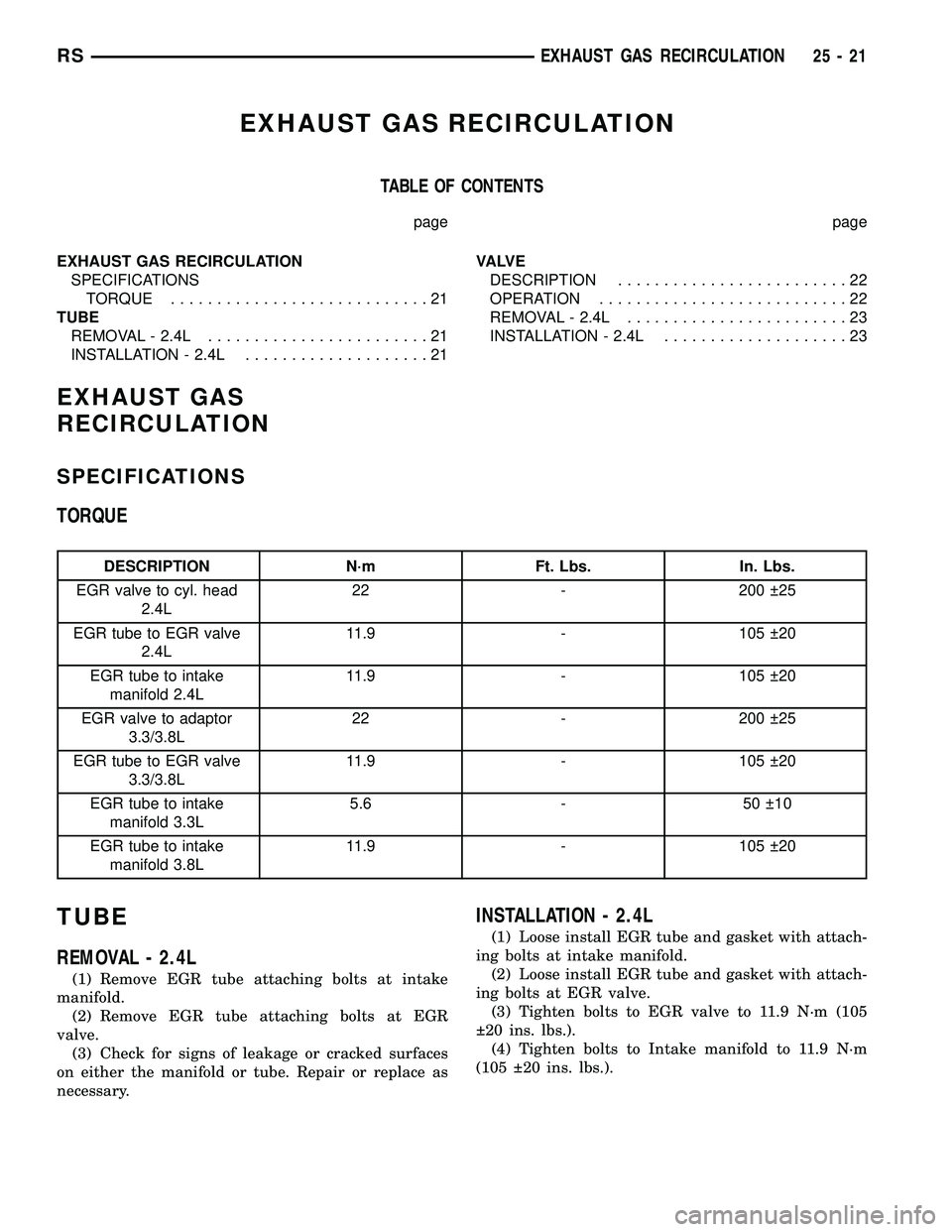
TORQUE
DESCRIPTION N´m Ft. Lbs. In. Lbs.
EGR valve to cyl. head
2.4L22 - 200 25
EGR tube to EGR valve
2.4L11.9 - 105 20
EGR tube to intake
manifold 2.4L11.9 - 105 20
EGR valve to adaptor
3.3/3.8L22 - 200 25
EGR tube to EGR valve
3.3/3.8L11.9 - 105 20
EGR tube to intake
manifold 3.3L5.6 - 50 10
EGR tube to intake
manifold 3.8L11.9 - 105 20
TUBE
REMOVAL - 2.4L
(1) Remove EGR tube attaching bolts at intake
manifold.
(2) Remove EGR tube attaching bolts at EGR
valve.
(3) Check for signs of leakage or cracked surfaces
on either the manifold or tube. Repair or replace as
necessary.
INSTALLATION - 2.4L
(1) Loose install EGR tube and gasket with attach-
ing bolts at intake manifold.
(2) Loose install EGR tube and gasket with attach-
ing bolts at EGR valve.
(3) Tighten bolts to EGR valve to 11.9 N´m (105
20 ins. lbs.).
(4) Tighten bolts to Intake manifold to 11.9 N´m
(105 20 ins. lbs.).
RSEXHAUST GAS RECIRCULATION25-21