Steering CHRYSLER VOYAGER 2005 Service Manual
[x] Cancel search | Manufacturer: CHRYSLER, Model Year: 2005, Model line: VOYAGER, Model: CHRYSLER VOYAGER 2005Pages: 2339, PDF Size: 59.69 MB
Page 499 of 2339
(12) Install the steering wheel (Refer to 19 -
STEERING/COLUMN/STEERING WHEEL -
INSTALLATION).
(13) Connect the 4±way harness connector to the
speed control/horn harness to the clockspring.
(14) Connect the 2±way connector to the remote
radio control harness.
(15) Install the driver airbag (Refer to 8 - ELEC-
TRICAL/RESTRAINTS/DRIVER AIRBAG - INSTAL-
LATION). Torque the two screws to 10 N´m (90 in.
lbs.).
WARNING: Do not connect the battery negative
cable (Refer to 8 - ELECTRICAL/RESTRAINTS -
DIAGNOSIS AND TESTING). Personal injury or
death may result if the system test is not performed
properly.
REMOVAL
(1) Position steering wheel and front wheels
straight ahead.
(2) Release hood latch and open hood.
(3) Disconnect and isolate the battery negative
cable.
(4)
WARNING: Wait two minutes for the airbag system
reserve capacitor to discharge before beginning
any airbag system or component service. Failure to
do so may result in accidental airbag deployment,
personal injury or death.
(5) Remove driver airbag from steering wheel
(Refer to 8 - ELECTRICAL/RESTRAINTS/DRIVER
AIRBAG - REMOVAL).
(6) Disconnect wire connectors from back of driver
airbag.
(7) Disconnect the 2±way connector from remote
radio control harness.
(8) Disconnect the 4±way harness connector from
the speed control/horn harness to the clockspring.
(9) Remove steering wheel (Refer to 19 - STEER-
ING/COLUMN/STEERING WHEEL - REMOVAL).
(10) Remove steering column shrouds and discon-
nect traction control wire connector (if equipped)
(Refer to 19 - STEERING/COLUMN/LOWER
SHROUD - REMOVAL).
(11) Disconnect 4-way and 6-way connectors
between the clockspring and the instrument panel
wiring harness.
(12) Remove clockspring from column assembly by
removing the two retaining screws that attach the
clock spring to the column.
INSTALLATION
(1) Install the clockspring on the column.
(2) Connect the 4-way and 6-way connectors
between the clockspring and the instrument panel
wiring harness.
(3) Install the steering column shrouds and con-
nect traction control wire connector (if equipped)
(Refer to 19 - STEERING/COLUMN/LOWER
SHROUD - INSTALLATION).
(4) Install the steering wheel (Refer to 19 -
STEERING/COLUMN/STEERING WHEEL -
INSTALLATION).
(5) Connect the 4±way harness connector to the
speed control/horn harness to the clockspring.
(6) Connect the 2±way connector to the remote
radio control harness (if equipped).
(7) Install the driver airbag (Refer to 8 - ELEC-
TRICAL/RESTRAINTS/DRIVER AIRBAG - INSTAL-
LATION). Torque the two screws to 10 N´m (90 in.
lbs.).
WARNING: Do not connect the battery negative
cable (Refer to 8 - ELECTRICAL/RESTRAINTS -
DIAGNOSIS AND TESTING - AIRBAG SYSTEM). Per-
sonal injury or death may result if the system test
is not performed first.
CURTAIN AIRBAG
DESCRIPTION
Curtain Airbags (Fig. 11) are available when it is
also equipped with dual front airbags. These airbags
are passive and inflatable, Supplemental Restraint
System (SRS) components, and vehicles with this
equipment can be readily identified by a molded
identification trim button with the ªSRS - AIRBAGº
logo (Fig. 12) located on the B-pillar and C-pillar
upper trim panels. This system is designed to reduce
injuries to the vehicle occupants in the event of a
side impact collision.
Curtain airbags have two individually controlled
curtain airbag units. These airbag units are con-
cealed and mounted above the headliner where they
are each secured to one of the roof side rails (Fig.
13). Each airbag cushion is contained within a fabric
wrap that extends along the roof rail from the A-pil-
lar at the front of the vehicle to just behind the
D-pillar at the rear of the vehicle. One tether extends
down the A-pillar from the front of the airbag cush-
ion, and a second tether extends to the roof rail at
the D-pillar. The end of the A-pillar tether is secured
to a slot in the sheet metal with a metal hook
retained by a bolt. The D-pillar tether is attached to
the d-pillar.
8O - 12 RESTRAINTSRS
CLOCKSPRING (Continued)
Page 503 of 2339
INSTALLATION
(1) Position curtain airbag over retaining holes in
roof rail and firmly snap into place (Fig. 17).
(2) Install the curtain airbag retaining bolts (Fig.
17).
(3) Engage the side curtain airbag front tether in
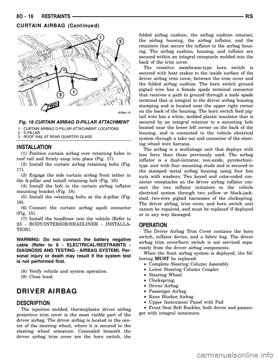
the A-pillar and install retaining bolt (Fig. 16).
(4) Install the bolt in the curtain airbag inflator
mounting bracket (Fig. 18).
(5) Install the retaining bolts at the d-pillar (Fig.
19).
(6) Connect the curtain airbag squib connector
(Fig. 15).
(7) Install the headliner into the vehicle (Refer to
23 - BODY/INTERIOR/HEADLINER - INSTALLA-
TION).
WARNING: Do not connect the battery negative
cable (Refer to 8 - ELECTRICAL/RESTRAINTS -
DIAGNOSIS AND TESTING - AIRBAG SYSTEM). Per-
sonal injury or death may result if the system test
is not performed first.
(8) Verify vehicle and system operation.
(9) Close hood.
DRIVER AIRBAG
DESCRIPTION
The injection molded, thermoplastic driver airbag
protective trim cover is the most visible part of the
driver airbag. The driver airbag is located in the cen-
ter of the steering wheel, where it is secured to the
steering wheel armature. Concealed beneath the
driver airbag trim cover are the horn switch, thefolded airbag cushion, the airbag cushion retainer,
the airbag housing, the airbag inflator, and the
retainers that secure the inflator to the airbag hous-
ing. The airbag cushion, housing, and inflator are
secured within an integral receptacle molded into the
back of the trim cover.
The resistive membrane-type horn switch is
secured with heat stakes to the inside surface of the
driver airbag trim cover, between the trim cover and
the folded airbag cushion. The horn switch ground
pigtail wire has a female spade terminal connector
that receives a path to ground through a male spade
terminal that is integral to the driver airbag housing
stamping and is located near the upper right corner
on the back of the housing. The horn switch feed pig-
tail wire has a white, molded plastic insulator that is
secured by an integral retainer to a mounting hole
located near the lower left corner on the back of the
housing, and is connected to the vehicle electrical
system through a take out and connector of the steer-
ing wheel wire harness.
The airbag is a multistage unit that deploys with
less force than those previously used. The airbag
inflator is a dual-initiator, non-azide, pyrotechnic-
type unit with four mounting studs and is secured to
the stamped metal airbag housing using four hex
nuts with washers. Two keyed and color-coded con-
nector receptacles on the driver airbag inflator con-
nect the two inflator initiators to the vehicle
electrical system through two yellow or black-jack-
eted, two-wire pigtail harnesses of the clockspring.
The driver airbag, trim cover, and horn switch unit
cannot be repaired, and must be replaced if deployed
or in any way damaged.
OPERATION
The Driver Airbag Trim Cover contains the horn
switch, inflator device, and a fabric bag. The driver
airbag trim cover/horn switch is not serviced sepa-
rately from the driver airbag components.
When the front airbag system is deployed, the fol-
lowingMUSTbe replaced:
²Complete Steering Column Assembly
²Lower Steering Column Coupler
²Steering Wheel.
²Clockspring.
²Driver Airbag
²Passenger Airbag
²Knee Blocker Airbag
²Upper Instrument Panel with Pad
²Front Seat Belt Buckles, both driver and passen-
ger with integral tensioners.
Fig. 19 CURTAIN AIRBAG D-PILLAR ATTACHMENT
1 - CURTAIN AIRBAG D-PILLAR ATTACHMENT LOCATIONS
2 - D-PILLAR
3 - ROOF RAIL AT REAR QUARTER GLASS
8O - 16 RESTRAINTSRS
CURTAIN AIRBAG (Continued)
Page 504 of 2339
CARE OF UNDEPLOYED AIRBAGS
WARNING: Airbags must be stored in their original
special container until used for service. At no time
should a source of electricity be permitted near the
inflator on the back of an airbag. When carrying or
handling an undeployed airbag, the trim side of the
airbag should be pointing toward the body to mini-
mize possibility of injury if accidental deployment
occurs. Do not place undeployed airbag face down
on a solid surface, the airbag will propel into the air
if accidental deployment occurs.
REMOVAL
DEPLOYED AIRBAG
(1) Clean powder residue from interior of vehicle
(Fig. 4).
(2) Position steering wheel and front wheels
straight ahead.
(3) Release hood latch and open hood.
(4) Disconnect and isolate the battery negative
cable.
(5)
WARNING: Wait two minutes for the airbag system
reserve capacitor to discharge before beginning
any airbag system or component service. Failure to
do so may result in accidental airbag deployment,
personal injury or death.
(6) Remove two screws retaining driver airbag to
steering wheel.
(7) Disconnect wire connectors from back of driver
airbag.
(8) Disconnect the 2±way connector from remote
radio control harness.
(9) Disconnect the 4±way harness connector from
the speed control/horn harness to the clockspring.
(10) Remove steering wheel (Refer to 19 - STEER-
ING/COLUMN/STEERING WHEEL - REMOVAL).
(11) Remove steering column shrouds and discon-
nect traction control wire connector (if equipped)
(Refer to 19 - STEERING/COLUMN/LOWER
SHROUD - REMOVAL).
(12) Disconnect 4-way and 6-way connectors
between the clockspring and the instrument panel
wiring harness.
(13) Remove clockspring from column assembly by
removing the two retaining screws that attach the
clockspring to the column.
WARNING: The clockspring, steering wheel, and
complete steering column assembly w/lower steer-
ing column coupler must be replaced also in theevent of a driver airbag deployment. Personal injury
or death may result if not replaced.
UNDEPLOYED AIRBAG
(1) Release hood latch and open hood.
(2) Disconnect and isolate the battery negative
cable.
WARNING: Wait two minutes for the system reserve
capacitor to discharge before beginning any airbag
component service. Personal injury or death may
result.
(3) Remove two screws retaining driver airbag to
steering wheel.
(4) Disconnect wire connectors from back of driver
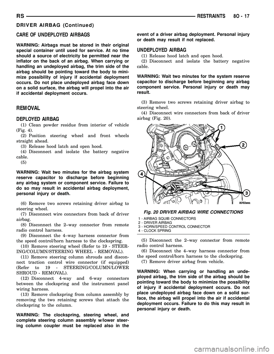
airbag (Fig. 20).
(5) Disconnect the 2±way connector from remote
radio control harness.
(6) Disconnect the 4±way harness connector from
the speed control/horn harness to the clockspring.
(7) Remove driver airbag from vehicle.
WARNING: When carrying or handling an unde-
ployed airbag, the trim side of the airbag should be
pointing toward the body to minimize the possibility
of injury if accidental deployment occurs. Do not
place undeployed airbag face down on a solid sur-
face, the airbag will propel into the air if accidental
deployment occurs. Failure to do this may result in
personal injury or death.
Fig. 20 DRIVER AIRBAG WIRE CONNECTIONS
1 - AIRBAG SQUIB CONNECTORS
2 - DRIVER AIRBAG
3 - HORN/SPEED CONTROL CONNECTOR
4 - CLOCK SPRING
RSRESTRAINTS8O-17
DRIVER AIRBAG (Continued)
Page 505 of 2339
INSTALLATION
DEPLOYED AIRBAG
(1) Perform clean up procedure (Refer to 8 - ELEC-
TRICAL/RESTRAINTS - STANDARD PROCEDURE
- SERVICE AFTER AN AIRBAG DEPLOYMENT).
(2) Install a new steering column assembly and
lower steering column coupler (Refer to 19 - STEER-
ING/COLUMN - INSTALLATION).
(3) Install the new clockspring.
(4) Connect the 4-way and 6-way connectors
between the clockspring and the instrument panel
wiring harness.
(5) Install the steering column shrouds and con-
nect traction control wire connector (if equipped)
(Refer to 19 - STEERING/COLUMN/LOWER
SHROUD - INSTALLATION).
(6) Install the steering wheel (Refer to 19 -
STEERING/COLUMN/STEERING WHEEL -
INSTALLATION).
(7) Connect the 4±way harness connector to the
speed control/horn harness to the clockspring.
(8) Connect the 2±way connector to the remote
radio control harness.
(9) Install the driver airbag and the two screws
retaining the airbag. Tighten screws to 10 N´m (90
in. lbs.)
WARNING: Do not connect the battery negative
cable (Refer to 8 - ELECTRICAL/RESTRAINTS -
DIAGNOSIS AND TESTING - AIRBAG SYSTEM). Per-
sonal injury or death may result if the system test
is not performed first.
UNDEPLOYED AIRBAG
(1) Connect the harness connector on the driver
airbag trim cover (horn, speed controls) to the clock-
spring.
(2) Connect the squib connectors to the driver air-
bag.
(3) Position the driver airbag into the steering
wheel.
(4) Install the two screws retaining the airbag.
Tighten screws to 10 N´m (90 in. lbs.)
WARNING: Do not connect the battery negative
cable (Refer to 8 - ELECTRICAL/RESTRAINTS -
DIAGNOSIS AND TESTING - AIRBAG SYSTEM). Per-
sonal injury or death may result if the system test
is not performed first.
IMPACT SENSOR
DESCRIPTION
FRONT IMPACT SENSORS
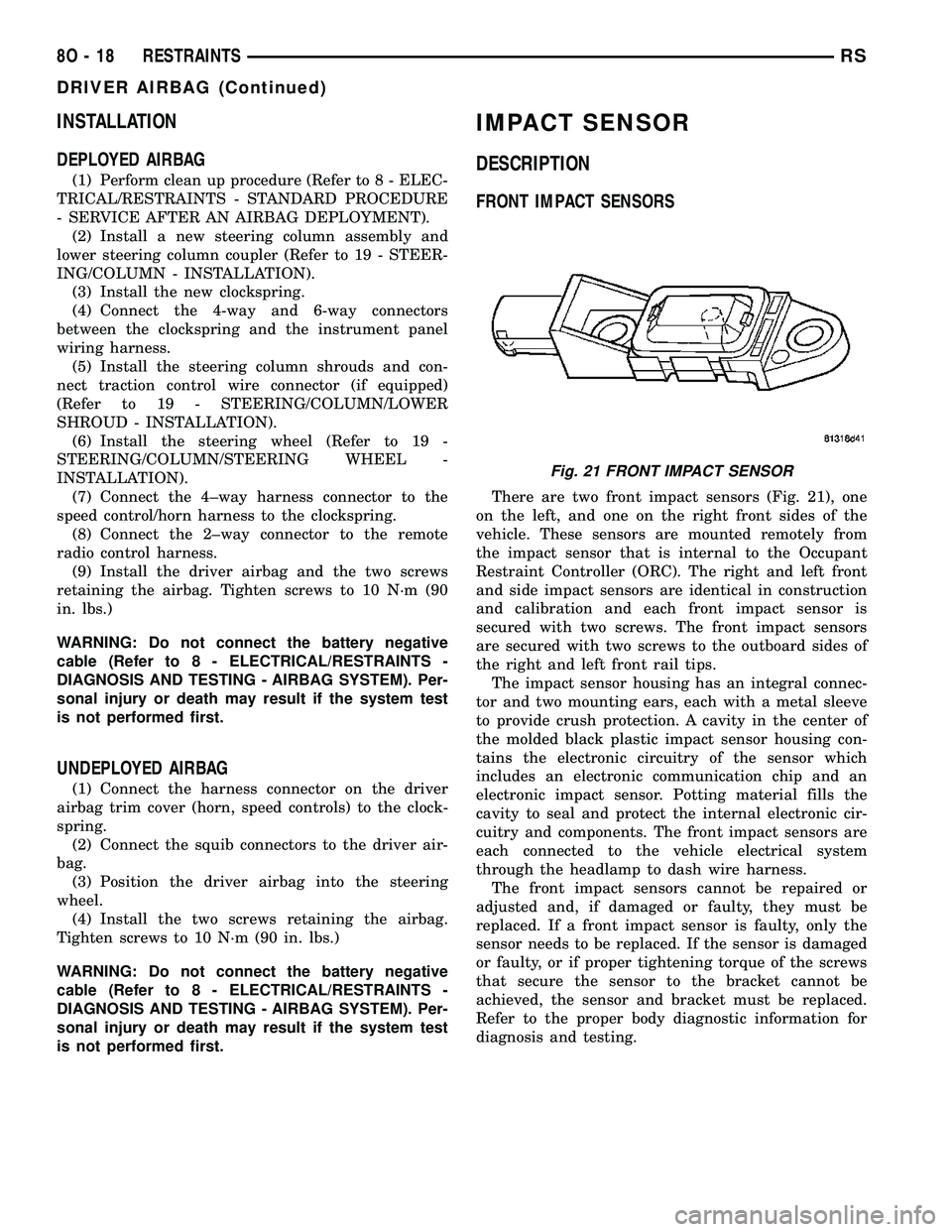
There are two front impact sensors (Fig. 21), one
on the left, and one on the right front sides of the
vehicle. These sensors are mounted remotely from
the impact sensor that is internal to the Occupant
Restraint Controller (ORC). The right and left front
and side impact sensors are identical in construction
and calibration and each front impact sensor is
secured with two screws. The front impact sensors
are secured with two screws to the outboard sides of
the right and left front rail tips.
The impact sensor housing has an integral connec-
tor and two mounting ears, each with a metal sleeve
to provide crush protection. A cavity in the center of
the molded black plastic impact sensor housing con-
tains the electronic circuitry of the sensor which
includes an electronic communication chip and an
electronic impact sensor. Potting material fills the
cavity to seal and protect the internal electronic cir-
cuitry and components. The front impact sensors are
each connected to the vehicle electrical system
through the headlamp to dash wire harness.
The front impact sensors cannot be repaired or
adjusted and, if damaged or faulty, they must be
replaced. If a front impact sensor is faulty, only the
sensor needs to be replaced. If the sensor is damaged
or faulty, or if proper tightening torque of the screws
that secure the sensor to the bracket cannot be
achieved, the sensor and bracket must be replaced.
Refer to the proper body diagnostic information for
diagnosis and testing.
Fig. 21 FRONT IMPACT SENSOR
8O - 18 RESTRAINTSRS
DRIVER AIRBAG (Continued)
Page 509 of 2339
WARNING: Do not connect the battery negative
cable (Refer to 8 - ELECTRICAL/RESTRAINTS -
DIAGNOSIS AND TESTING - AIRBAG SYSTEM). Per-
sonal injury or death may result if the system test
is not performed first.
(5) Verify vehicle and system operation.
(6) Close hood.
SLIDING DOOR OPENING MOUNTED
(1) Connect electrical connector (Fig. 27).
(2) Position sensor in vehicle (Fig. 27).
(3) Install the two retaining screws to the impact
sensor (Fig. 27). Torque screws to 7 N´m (62 in. lbs.).
WARNING: Do not connect the battery negative
cable (Refer to 8 - ELECTRICAL/RESTRAINTS -
DIAGNOSIS AND TESTING - AIRBAG SYSTEM). Per-
sonal injury or death may result if the system test
is not performed first.
(4) Verify vehicle and system operation.
(5) Close hood.
QUARTER PANEL MOUNTED
(1) Position sensor in vehicle (Fig. 28).
(2) Connect electrical connector (Fig. 28).
(3) Install the two retaining screws to the impact
sensor (Fig. 28). Torque screws to 7 N´m (62 in. lbs.).
(4) Install the quarter trim panel for the side of
the vehicle that you are replacing the side impact
sensor (Refer to 23 - BODY/INTERIOR/QUARTER
TRIM PANEL - INSTALLATION).
WARNING: Do not connect the battery negative
cable (Refer to 8 - ELECTRICAL/RESTRAINTS -
DIAGNOSIS AND TESTING - AIRBAG SYSTEM). Per-
sonal injury or death may result if the system test
is not performed first.
(5) Verify vehicle and system operation.
(6) Close hood.
KNEE BLOCKER AIRBAG
DESCRIPTION
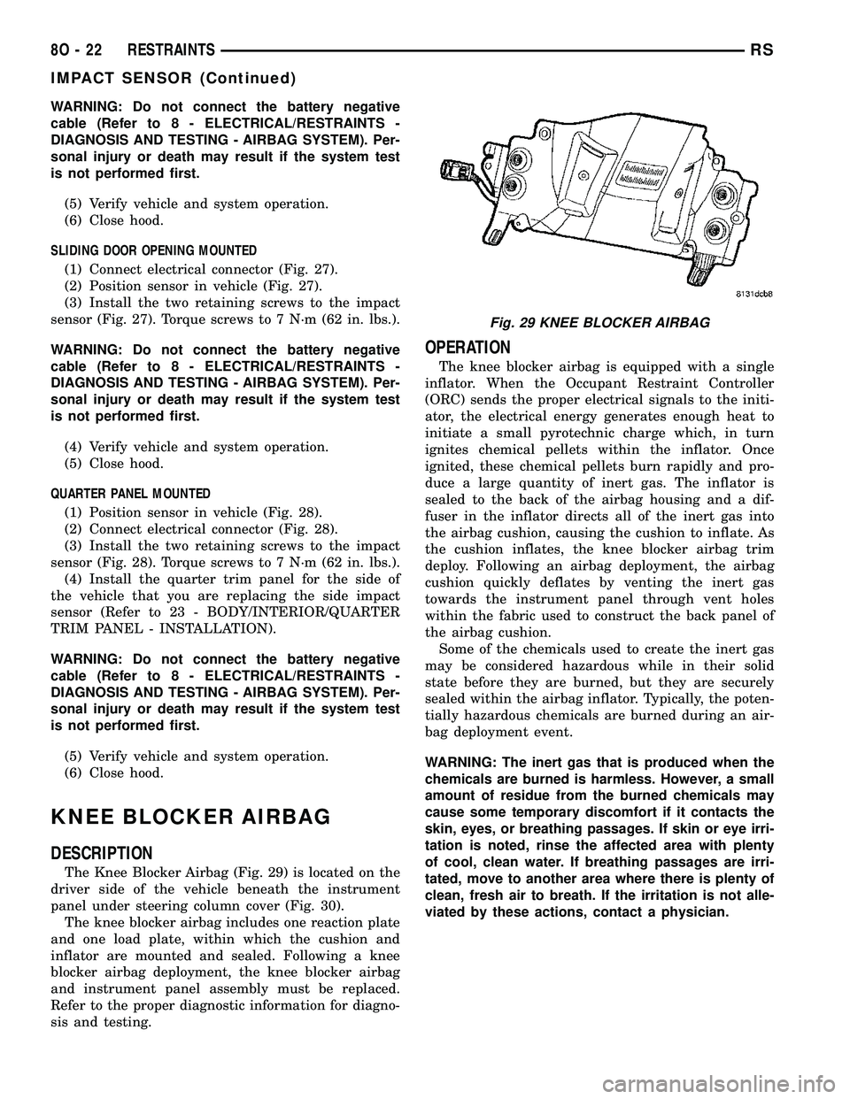
The Knee Blocker Airbag (Fig. 29) is located on the
driver side of the vehicle beneath the instrument
panel under steering column cover (Fig. 30).
The knee blocker airbag includes one reaction plate
and one load plate, within which the cushion and
inflator are mounted and sealed. Following a knee
blocker airbag deployment, the knee blocker airbag
and instrument panel assembly must be replaced.
Refer to the proper diagnostic information for diagno-
sis and testing.
OPERATION
The knee blocker airbag is equipped with a single
inflator. When the Occupant Restraint Controller
(ORC) sends the proper electrical signals to the initi-
ator, the electrical energy generates enough heat to
initiate a small pyrotechnic charge which, in turn
ignites chemical pellets within the inflator. Once
ignited, these chemical pellets burn rapidly and pro-
duce a large quantity of inert gas. The inflator is
sealed to the back of the airbag housing and a dif-
fuser in the inflator directs all of the inert gas into
the airbag cushion, causing the cushion to inflate. As
the cushion inflates, the knee blocker airbag trim
deploy. Following an airbag deployment, the airbag
cushion quickly deflates by venting the inert gas
towards the instrument panel through vent holes
within the fabric used to construct the back panel of
the airbag cushion.
Some of the chemicals used to create the inert gas
may be considered hazardous while in their solid
state before they are burned, but they are securely
sealed within the airbag inflator. Typically, the poten-
tially hazardous chemicals are burned during an air-
bag deployment event.
WARNING: The inert gas that is produced when the
chemicals are burned is harmless. However, a small
amount of residue from the burned chemicals may
cause some temporary discomfort if it contacts the
skin, eyes, or breathing passages. If skin or eye irri-
tation is noted, rinse the affected area with plenty
of cool, clean water. If breathing passages are irri-
tated, move to another area where there is plenty of
clean, fresh air to breath. If the irritation is not alle-
viated by these actions, contact a physician.
Fig. 29 KNEE BLOCKER AIRBAG
8O - 22 RESTRAINTSRS
IMPACT SENSOR (Continued)
Page 510 of 2339

REMOVAL
(1) Open hood, disconnect and isolate the battery
negative cable.
(2)
WARNING: Wait two minutes for the airbag system
reserve capacitor to discharge before beginning
any airbag system or component service. Failure to
do so may result in accidental airbag deployment,
personal injury or death.
(3) Remove the steering column opening cover two
retaining screws (Fig. 31) and unsnap cover from
instrument panel (Refer to 23 - BODY/INSTRU-
MENT PANEL/STEERING COLUMN OPENING
COVER - REMOVAL).
(4) Disconnect the knee blocker airbag electrical
connector (Fig. 32).
(5) Remove five knee blocker airbag retaining bolts
from airbag (Fig. 33).
(6) Remove knee blocker airbag from vehicle.
INSTALLATION
(1) Place the knee blocker airbag into position in
the instrument panel opening (Fig. 33).
(2) Connect the one electrical connector (Fig. 32).
(3) Install the five knee blocker airbag retaining
bolts (Fig. 33).
(4) Position the steering column opening cover
over retaining slots and firmly snap into place (Fig.
31). Install the two retaining screws (Fig. 31) (Refer
to 23 - BODY/INSTRUMENT PANEL/STEERING
COLUMN OPENING COVER - INSTALLATION).
WARNING: Do not connect the battery negative
cable (Refer to 8 - ELECTRICAL/RESTRAINTS -
DIAGNOSIS AND TESTING - AIRBAG SYSTEM). Per-
sonal injury or death may result if the system test
is not performed first.
(5) Verify vehicle and system operation.
(6) Close hood.
Fig. 30 KNEE BLOCKER AIRBAG LOCATION
1 - KNEE BLOCKER AIRBAG 3 - UNDER STEERING COLUMN COVER RETAINING SCREWS
2 - UNDER STEERING C0LUMN COVER
RSRESTRAINTS8O-23
KNEE BLOCKER AIRBAG (Continued)
Page 511 of 2339

Fig. 31 STEERING COLUMN OPENING COVER
1 - KNEE BLOCKER AIRBAG 3 - UNDER STEERING COLUMN COVER RETAINING SCREWS
2 - UNDER STEERING C0LUMN COVER
Fig. 32 KNEE BLOCKER AIRBAG ELECTRICAL
CONNECTOR
1 - KNEE BLOCKER AIRBAG
2 - INSTRUMENT PANEL
3 - KNEE BLOCKER AIRBAG ELECTRICAL CONNECTOR
Fig. 33 KNEE BLOCKER AIRBAG - REMOVE/
INSTALL
1 - KNEE BLOCKER AIRBAG RETAINING SCREWS
2 - KNEE BLOCKER AIRBAG
3 - KNEE BLOCKER AIRBAG ELECTRICAL CONNECTOR
4 - INSTRUMENT PANEL
8O - 24 RESTRAINTSRS
KNEE BLOCKER AIRBAG (Continued)
Page 517 of 2339
WARNING: Never replace both the Occupant
Restraint Controller (ORC) and the Occupant Clas-
sification Module (OCM) at the same time. If both
require replacement, replace one, then perform the
Airbag System test (Refer to 8 - ELECTRICAL/RE-
STRAINTS - DIAGNOSIS AND TESTING - AIRBAG
SYSTEM) before replacing the other. Both the ORC
and the OCM store Occupant Classification System
(OCS) calibration data, which they transfer to one
another when one of them is replaced. If both are
replaced at the same time, an irreversible fault will
be set in both modules and the OCS may malfunc-
tion and result in personal injury or death.
(1) Install the ORC into vehicle (Fig. 39).
(2) Connect the wire connector to the ORC (Fig.
39).
(3) Install three bolts holding ORC to floor bracket
(Fig. 39). Torque bolts to 7.3 - 9.6 N´m (65 to 85 in.
lbs.)
(4) Install the storage bin onto the instrument
panel (Refer to 23 - BODY/INSTRUMENT PANEL/
STORAGE BIN - INSTALLATION).
WARNING: Do not connect the battery negative
cable (Refer to 8 - ELECTRICAL/RESTRAINTS -
DIAGNOSIS AND TESTING - AIRBAG SYSTEM). Per-
sonal injury or death may result if the system test
is not performed first.
(5) Verify vehicle and system operation.
(6) Close hood.
PASSENGER AIRBAG
DESCRIPTION
WARNING: Never disassemble the passenger air-
bag. The passenger airbag has no serviceable
parts. If tampered with internally, the airbag could
deploy and result in personal injury or death.
The Passenger Airbag is located beneath the
instrument panel and pad assembly. The airbag is
mounted to the back side of the instrument panel
reinforcement.
The instrument panel top pad is the most visible
part of the passenger airbag system. Located under
the instrument panel top pad are the airbag door, the
passenger airbag cushion and the airbag cushion
supporting components.
The passenger airbag includes a magnesium hous-
ing within which the cushion and inflator are
mounted and sealed.
Following a passenger airbag deployment, the pas-
senger airbag and the instrument panel must bereplaced. The passenger airbag cannot be repaired,
and must be replaced if deployed or damaged in any
way.
OPERATION
The passenger airbag is equipped with two infla-
tors, each with three levels of pressure output. The
inflators seal the hole in the airbag cushion so it can
discharge the gas it produces directly into the cush-
ion when supplied with the proper electrical signal.
Following an airbag deployment, the airbag cushion
quickly deflates by venting this gas through the
cushion material towards the instrument panel.
The passenger airbag is secured with screws to the
instrument panel beneath the instrument panel top
pad and above the glove box opening. The instrument
panel top pad above the glove box opening conceals
the airbag door and a predetermined hinge line
beneath its decorative cover. Upon airbag deploy-
ment, the top pad will bend at the hinge line and the
door will fold back out of the way onto the top of the
instrument panel.
When the front airbag system is deployed, the fol-
lowingMUSTbe replaced:
²Complete Steering Column Assembly.
²Lower Steering Column Coupler.
²Steering Wheel.
²Clock Spring.
²Driver Airbag.
²Passenger Airbag.
²Upper Instrument Panel with Pad.
CARE OF UNDEPLOYED AIRBAGS
Airbags must be stored in their original special
container until used for service. At no time should a
source of electricity be permitted near the inflator on
the back of an airbag. When carrying or handling an
undeployed airbag, the trim side of the airbag should
be pointing away from the body to minimize possibil-
ity of injury if accidental deployment occurs. Do not
place undeployed airbag face down on a solid surface,
the airbag will propel into the air if accidental
deployment occurs.
REMOVAL
DEPLOYED AIRBAG
(1) Open hood.
(2) Disconnect and isolate the battery negative
cable.
(3)
8O - 30 RESTRAINTSRS
OCCUPANT RESTRAINT CONTROLLER (Continued)
Page 518 of 2339

WARNING: Wait two minutes for the airbag system
reserve capacitor to discharge before beginning
any airbag system or component service. Failure to
do so may result in accidental airbag deployment,
personal injury or death.
(4) Clean powder residue from interior of vehicle
(Refer to 8 - ELECTRICAL/RESTRAINTS - STAN-
DARD PROCEDURE - SERVICE AFTER AN AIR-
BAG DEPLOYMENT).
(5) Remove instrument panel (Refer to 23 - BODY/
INSTRUMENT PANEL/INSTRUMENT PANEL
ASSEMBLY - REMOVAL).
(6) Remove all reusable components from the
upper instrument panel and transfer to the new
instrument panel.
UNDEPLOYED AIRBAG
(1) Open hood.
(2) Disconnect and isolate the battery negative
cable.
(3)
WARNING: Wait two minutes for the airbag system
reserve capacitor to discharge before beginning
any airbag system or component service. Failure to
do so may result in accidental airbag deployment,
personal injury or death.
(4) Remove center console bin between front seats.
(5) Remove left front door sill plate using a trim
stick (special tool #C-4755) or equivalent, and gently
prying up on sill plate.
(6) Remove left cowl panel using a trim stick or
equivalent, and gently prying out on cowl panel.
(7) Remove four screws to lower steering column
cover and remove cover.
(8) Unsnap parking brake lever from knee blocker
reinforcement.
(9) Remove Data Link Connector (DLC) from knee
blocker.
(10) Remove screws to knee blocker.
(11) Unsnap left A-pillar lower extension trim
using a trim stick or equivalent.
(12) Remove three left side instrument panel A-pil-
lar retaining bolts and loosen the instrument panel
roll down bolt.
(13) Remove four nuts at brake pedal support
bracket to instrument panel.
(14) Using a trim stick or equivalent, gently pry
off left side upper A-pillar trim.
(15) Remove six screws and two wiring connectors
to lower instrument panel cubby bin at bottom of
center stack.
(16) Remove two left side nuts at instrument panel
center stack support to floor.(17) Remove two right side nuts at instrument
panel center stack support to floor.
(18) Remove right front door sill plate using a trim
stick or equivalent, and gently prying up on sill
plate.
(19) Remove right cowl panel using a trim stick or
equivalent, and gently prying out on cowl panel.
(20) Using a trim stick or equivalent, gently pry
out on right instrument panel end cap.
(21) Unsnap right A-pillar lower extension trim
using a trim stick or equivalent.
(22) Remove three right side instrument panel
A-pillar retaining bolts and loosen the instrument
panel roll down bolt.
(23) Using a trim stick or equivalent, gently pry
off right side upper A-pillar trim.
(24) Open glove box, pinch in sides and roll down
towards floor. With a firm pull, snap glove box door
off hinges and remove.
(25) Using a trim stick or equivalent, gently pry
up on rear of instrument panel top cover and then
pull rearward and out.
(26) Using a trim stick or equivalent, gently pry
off the filler bezel just above the cup holder to expose
the lower screws to center bezel.
(27) Remove two screws and then using a trim
stick or equivalent, gently pry off instrument panel
center bezel.
(28) Remove center bezel wiring connectors to
HVAC control and switch assembly (hazard, rear
wiper/washer, heated seats) and remove bezel.
(29) Slide cup holder assembly from instrument
panel.
(30) Remove nineteen screws to right lower instru-
ment panel trim (glove box surround), unplug glove
box lamp wire connector, and remove panel.
(31) Remove four screws and wiring connectors to
radio and remove radio.
(32) Remove one far left instrument panel speaker
retaining screw.
(33) Remove four screws along top front edge of
instrument panel cover/pad.
(34) Remove seven lower instrument panel cover/
pad retaining screws starting from right of vehicle
and only removing these seven, not all of them.
(35) Remove six upper fence line instrument panel
retaining bolts.
(36) Roll back instrument panel just enough to
increase access to the passenger airbag retaining
bolts at the reinforcement. Lift the instrument panel
up slightly so as not to damage the air distribution to
HVAC unit seal.
(37) Disconnect the passenger airbag electrical
connector. Using a trim stick or equivalent, gently
pry electrical connector off of instrument panel rein-
forcement.
RSRESTRAINTS8O-31
PASSENGER AIRBAG (Continued)
Page 520 of 2339
(28) Install two right side nuts at instrument
panel center stack support to floor.
(29) Install two left side nuts at instrument panel
center stack support to floor.
(30) Connect the two wiring connectors to lower
instrument panel cubby bin at bottom of center stack
and install six screws.
(31) Align left side upper A-pillar trim over retain-
ing slots and firmly snap into place.
(32) Install four nuts at brake pedal support
bracket to instrument panel.
(33) Align left A-pillar lower extension trim over
retaining slots and firmly snap into place.
(34) Install knee blocker and retaining screws.
(35) Install Data Link Connector (DLC) into bot-
tom of knee blocker.
(36) Align parking brake lever and snap into place
on knee blocker reinforcement.
(37) Install lower steering column cover and four
retaining screws
(38) Align left cowl panel over retaining slots and
firmly snap into place.
(39) Align left front door sill plate over retaining
slots and firmly snap into place.
(40) Install center console bin between front seats.
WARNING: Do not connect the battery negative
cable (Refer to 8 - ELECTRICAL/RESTRAINTS -
DIAGNOSIS AND TESTING - AIRBAG SYSTEM). Per-
sonal injury or death may result if the system test
is not performed first.
(41) Close hood.
(42) Verify system and vehicle operation.
PASSENGER AIRBAG
DISABLED INDICATOR
DESCRIPTION
Vehicles equipped with the Occupant Classification
System (OCS) include a Passenger Airbag Disabled
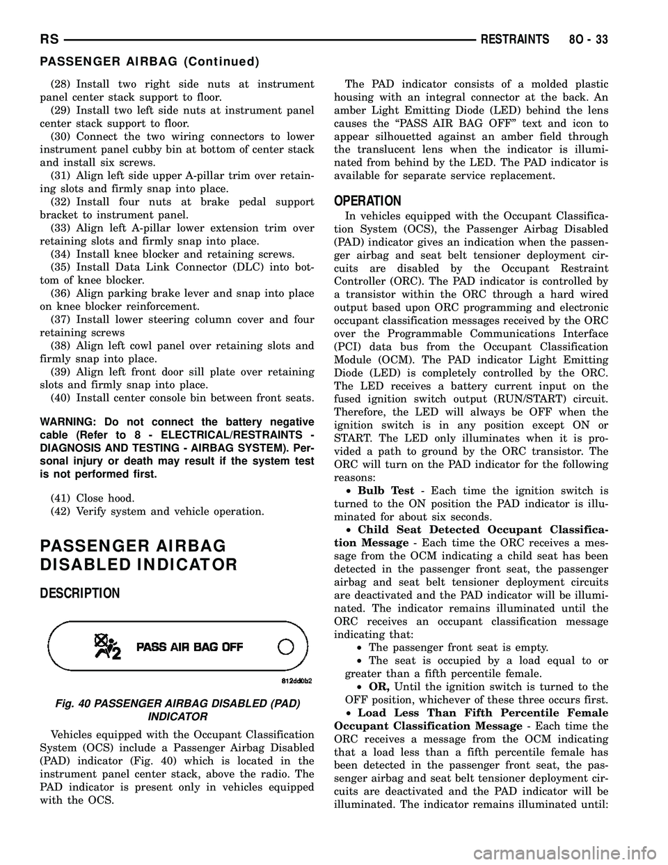
(PAD) indicator (Fig. 40) which is located in the
instrument panel center stack, above the radio. The
PAD indicator is present only in vehicles equipped
with the OCS.The PAD indicator consists of a molded plastic
housing with an integral connector at the back. An
amber Light Emitting Diode (LED) behind the lens
causes the ªPASS AIR BAG OFFº text and icon to
appear silhouetted against an amber field through
the translucent lens when the indicator is illumi-
nated from behind by the LED. The PAD indicator is
available for separate service replacement.
OPERATION
In vehicles equipped with the Occupant Classifica-
tion System (OCS), the Passenger Airbag Disabled
(PAD) indicator gives an indication when the passen-
ger airbag and seat belt tensioner deployment cir-
cuits are disabled by the Occupant Restraint
Controller (ORC). The PAD indicator is controlled by
a transistor within the ORC through a hard wired
output based upon ORC programming and electronic
occupant classification messages received by the ORC
over the Programmable Communications Interface
(PCI) data bus from the Occupant Classification
Module (OCM). The PAD indicator Light Emitting
Diode (LED) is completely controlled by the ORC.
The LED receives a battery current input on the
fused ignition switch output (RUN/START) circuit.
Therefore, the LED will always be OFF when the
ignition switch is in any position except ON or
START. The LED only illuminates when it is pro-
vided a path to ground by the ORC transistor. The
ORC will turn on the PAD indicator for the following
reasons:
²Bulb Test- Each time the ignition switch is
turned to the ON position the PAD indicator is illu-
minated for about six seconds.
²Child Seat Detected Occupant Classifica-
tion Message- Each time the ORC receives a mes-
sage from the OCM indicating a child seat has been
detected in the passenger front seat, the passenger
airbag and seat belt tensioner deployment circuits
are deactivated and the PAD indicator will be illumi-
nated. The indicator remains illuminated until the
ORC receives an occupant classification message
indicating that:
²The passenger front seat is empty.
²The seat is occupied by a load equal to or
greater than a fifth percentile female.
²OR,Until the ignition switch is turned to the
OFF position, whichever of these three occurs first.
²Load Less Than Fifth Percentile Female
Occupant Classification Message- Each time the
ORC receives a message from the OCM indicating
that a load less than a fifth percentile female has
been detected in the passenger front seat, the pas-
senger airbag and seat belt tensioner deployment cir-
cuits are deactivated and the PAD indicator will be
illuminated. The indicator remains illuminated until:
Fig. 40 PASSENGER AIRBAG DISABLED (PAD)
INDICATOR
RSRESTRAINTS8O-33
PASSENGER AIRBAG (Continued)