Steering CHRYSLER VOYAGER 2005 Service Manual
[x] Cancel search | Manufacturer: CHRYSLER, Model Year: 2005, Model line: VOYAGER, Model: CHRYSLER VOYAGER 2005Pages: 2339, PDF Size: 59.69 MB
Page 530 of 2339
SEAT BELT TENSIONER
DESCRIPTION
The seat belt system incorporates Seat Belt Ten-
sioners. The tensioner is designed to hold the occu-
pant in their respective seat by retracting the seat
belt up to four inches. They are integral to the front
seat belt buckles and cannot be serviced. If found
defective they must be replaced. After an airbag
deployment, the tensioner must be replaced.
Seat Belt Tensioners supplement the dual front air-
bag system. The seat belt tensioners are integral to
the front seat belt buckles, which are secured to the
seat cushion frame on the inboard side. The seat belt
tensioners are controlled by the Occupant Restraint
Controller (ORC) and are connected to the vehicle
electrical system through the body wire harness.
The seat belt tensioners cannot be repaired and, if
faulty or damaged, the entire front seat belt buckle
must be replaced. The seat belt tensioners are not
intended for reuse and must be replaced following
any front airbag deployment.
OPERATION
WARNING: When the front airbag is deployed, the
tensioner will have deployed also and should be
replaced. Failure to do so could result in occupant
personal injury or death.
The seat belt tensioners are deployed by a signal
generated by the Occupant Restraint Controller
(ORC) through the driver or passenger seat belt ten-
sioner line 1 and line 2 (or squib) circuits. When the
ORC sends the proper electrical signal to the tension-
ers, the electrical energy generates enough heat to
initiate a small pyrotechnic gas generator.
Removing excess slack from the front seat belts not
only keeps the occupants properly positioned for an
airbag deployment following a frontal impact of the
vehicle, but also helps to reduce injuries that the
occupants of the front seat might experience in these
situations as a result of a harmful contact with the
steering wheel, steering column, instrument panel
and/or windshield.
The ORC monitors the condition of the seat belt
tensioners through circuit resistance, and will illumi-
nate the airbag indicator in the ElectroMechanical
Instrument Cluster (EMIC) and store a Diagnostic
Trouble Code (DTC) for any fault that is detected.
For proper diagnosis of the seat belt tensioners, use a
scan tool and the appropriate diagnostic information.
SEAT WEIGHT BLADDER &
PRESSURE SENSOR
DESCRIPTION
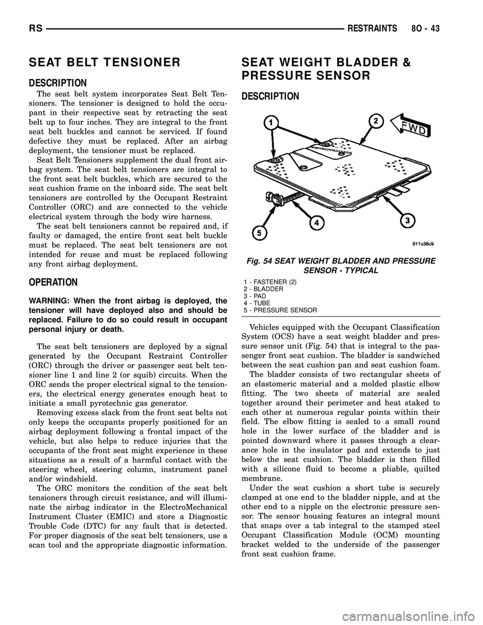
Vehicles equipped with the Occupant Classification
System (OCS) have a seat weight bladder and pres-
sure sensor unit (Fig. 54) that is integral to the pas-
senger front seat cushion. The bladder is sandwiched
between the seat cushion pan and seat cushion foam.
The bladder consists of two rectangular sheets of
an elastomeric material and a molded plastic elbow
fitting. The two sheets of material are sealed
together around their perimeter and heat staked to
each other at numerous regular points within their
field. The elbow fitting is sealed to a small round
hole in the lower surface of the bladder and is
pointed downward where it passes through a clear-
ance hole in the insulator pad and extends to just
below the seat cushion. The bladder is then filled
with a silicone fluid to become a pliable, quilted
membrane.
Under the seat cushion a short tube is securely
clamped at one end to the bladder nipple, and at the
other end to a nipple on the electronic pressure sen-
sor. The sensor housing features an integral mount
that snaps over a tab integral to the stamped steel
Occupant Classification Module (OCM) mounting
bracket welded to the underside of the passenger
front seat cushion frame.
Fig. 54 SEAT WEIGHT BLADDER AND PRESSURE
SENSOR - TYPICAL
1 - FASTENER (2)
2 - BLADDER
3-PAD
4 - TUBE
5 - PRESSURE SENSOR
RSRESTRAINTS8O-43
Page 532 of 2339
SPEED CONTROL
TABLE OF CONTENTS
page page
SPEED CONTROL
DESCRIPTION..........................1
OPERATION
OPERATION..........................1
OPERATION - INTERACTIVE SPEED
CONTROL (4 Speed EATX Only)...........2
DIAGNOSIS AND TESTING - ROAD TEST.....3
SPECIFICATIONS - TORQUE...............3
CABLE
DESCRIPTION..........................4
OPERATION............................4
REMOVAL.............................4
INSTALLATION..........................4
SERVO
DESCRIPTION..........................4OPERATION............................4
REMOVAL.............................4
INSTALLATION..........................4
SWITCH
DESCRIPTION..........................5
OPERATION............................5
REMOVAL.............................5
INSTALLATION..........................6
VACUUM RESERVOIR
DESCRIPTION..........................6
OPERATION............................6
REMOVAL.............................6
INSTALLATION..........................6
SPEED CONTROL
DESCRIPTION
The speed control system is electronically con-
trolled and vacuum operated. The electronic control
is integrated into the Powertrain Control Module.
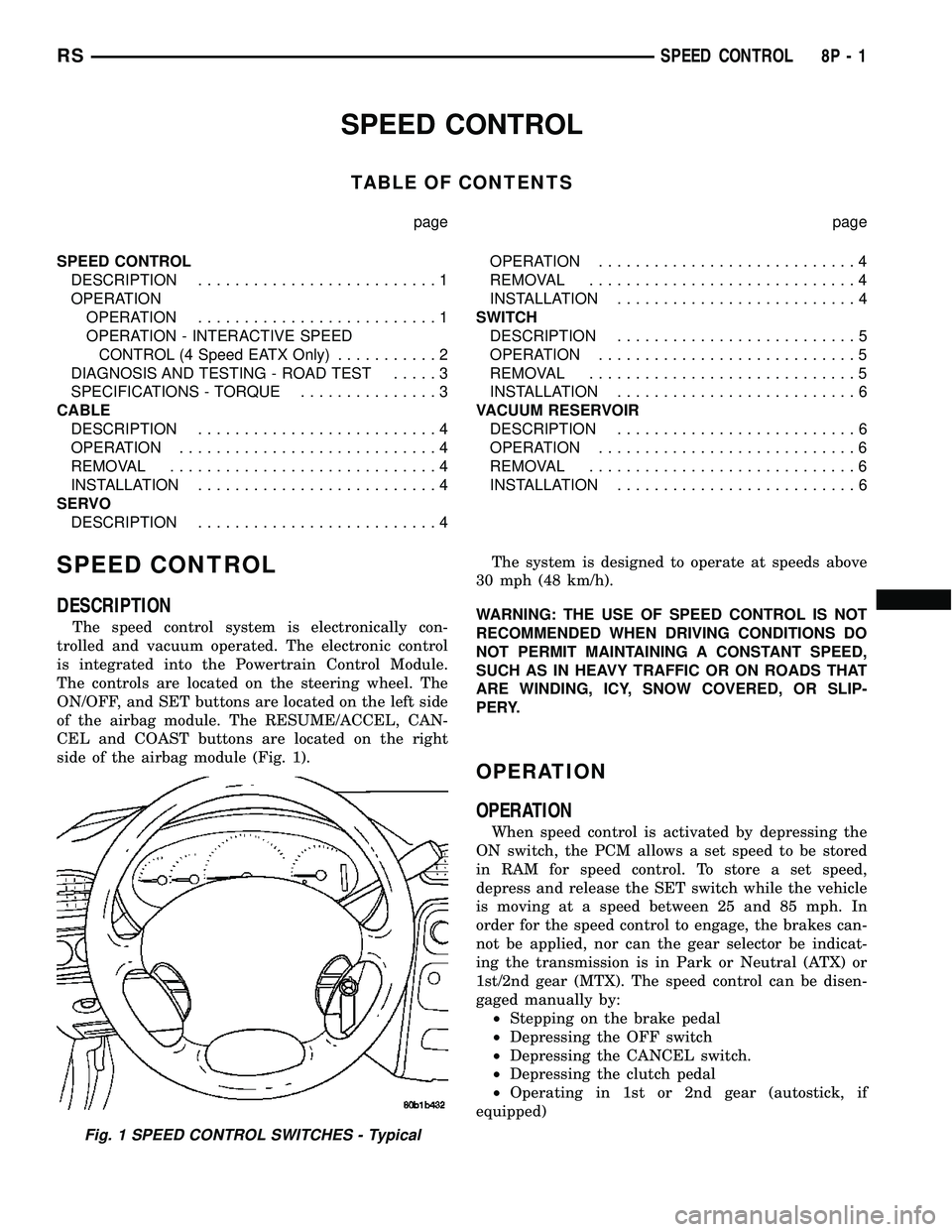
The controls are located on the steering wheel. The
ON/OFF, and SET buttons are located on the left side
of the airbag module. The RESUME/ACCEL, CAN-
CEL and COAST buttons are located on the right
side of the airbag module (Fig. 1).The system is designed to operate at speeds above
30 mph (48 km/h).
WARNING: THE USE OF SPEED CONTROL IS NOT
RECOMMENDED WHEN DRIVING CONDITIONS DO
NOT PERMIT MAINTAINING A CONSTANT SPEED,
SUCH AS IN HEAVY TRAFFIC OR ON ROADS THAT
ARE WINDING, ICY, SNOW COVERED, OR SLIP-
PERY.
OPERATION
OPERATION
When speed control is activated by depressing the
ON switch, the PCM allows a set speed to be stored
in RAM for speed control. To store a set speed,
depress and release the SET switch while the vehicle
is moving at a speed between 25 and 85 mph. In
order for the speed control to engage, the brakes can-
not be applied, nor can the gear selector be indicat-
ing the transmission is in Park or Neutral (ATX) or
1st/2nd gear (MTX). The speed control can be disen-
gaged manually by:
²Stepping on the brake pedal
²Depressing the OFF switch
²Depressing the CANCEL switch.
²Depressing the clutch pedal
²Operating in 1st or 2nd gear (autostick, if
equipped)
Fig. 1 SPEED CONTROL SWITCHES - Typical
RSSPEED CONTROL8P-1
Page 536 of 2339
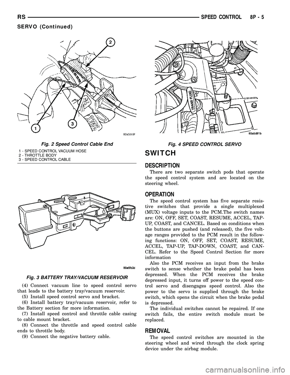
(4) Connect vacuum line to speed control servo
that leads to the battery tray/vacuum reservoir.
(5) Install speed control servo and bracket.
(6) Install battery tray/vacuum reservoir, refer to
the Battery section for more information.
(7) Install speed control and throttle cable casing
to cable mount bracket.
(8) Connect the throttle and speed control cable
ends to throttle body.
(9) Connect the negative battery cable.
SWITCH
DESCRIPTION
There are two separate switch pods that operate
the speed control system and are located on the
steering wheel.
OPERATION
The speed control system has five separate resis-
tive switches that provide a single multiplexed
(MUX) voltage inputs to the PCM.The switch names
are: ON, OFF, SET, COAST, RESUME, ACCEL, TAP-
UP, COAST, and CANCEL. Based on conditions when
the buttons are pushed (and released), the five volt-
age ranges provided to the PCM result in the follow-
ing functions: ON, OFF, SET, COAST, RESUME,
ACCEL, TAP-UP, TAP-DOWN, COAST, and CAN-
CEL. Refer to the Speed Control Section for more
information
Also the PCM receives an input from the brake
switch to sense whether the brake pedal has been
depressed. When the PCM receives the brake
depressed input, it turns off power to the speed con-
trol servo and disengages speed control. Also the
power to the servo is supplied through the brake
switch, which opens the circuit when the brake pedal
is depressed.
The individual switches cannot be repaired. If one
switch fails, the entire switch module must be
replaced.
REMOVAL
The speed control switches are mounted in the
steering wheel and wired through the clock spring
device under the airbag module.
Fig. 2 Speed Control Cable End
1 - SPEED CONTROL VACUUM HOSE
2 - THROTTLE BODY
3 - SPEED CONTROL CABLE
Fig. 3 BATTERY TRAY/VACUUM RESERVOIR
Fig. 4 SPEED CONTROL SERVO
RSSPEED CONTROL8P-5
SERVO (Continued)
Page 537 of 2339
WARNING: IF REMOVAL OF AIRBAG MODULE IS
NECESSARY, REFER TO THE RESTRAINT SYS-
TEMS SECTION FOR MORE INFORMATION.
(1) Remove the negative battery cable.
(2) Turn off ignition.
(3) Remove the air bag, refer to the restraint sec-
tion for more information.
(4) Remove the screw from bottom of the switch.
(5) Remove switch from steering wheel.
(6) Disconnect two-way electrical connector.
(7) Repeat for the other switch.
INSTALLATION
The speed control switches are mounted in the
steering wheel and wired through the clock spring
device under the airbag module.
WARNING: IF REMOVAL OF AIRBAG MODULE IS
NECESSARY, REFER TO THE RESTRAINT SYS-
TEMS SECTION FOR MORE INFORMATION.
(1) Connect two-way electrical connector.
(2) Install switch.
(3) Install screw for the switch.
(4) Repeat for the other switch.
(5) Install the air bag, refer to the restraint section
for more information.
(6) Install the negative battery cable.
VACUUM RESERVOIR
DESCRIPTION
The vacuum reservoir is located in the engine com-
partment. It is made of plastic.
OPERATION
The reservoir stores engine vacuum. Manifold vac-
uum is supplied from the brake booster check valve.
The speed control vacuum supply hose has a check
valve at the source (brake booster) to maintain the
highest available vacuum level in the servo, reservoir
and vacuum hoses. When engine vacuum drops, as in
climbing a grade while driving, the reservoir supplies
the vacuum needed to maintain proper speed control
operation. The vacuum reservoir cannot be repaired
and must be replaced if faulty.
REMOVAL
(1) Release hood latch and open hood.
(2) Disconnect the negative battery cable.
(3) Disconnect the vacuum line to the battery tray/
vacuum reservoir.
(4) Remove battery tray/vacuum reservoir, refer to
the Battery section for more information.
INSTALLATION
(1) Install battery tray/vacuum reservoir, refer to
the Battery section for more information.
(2) Connect vacuum line that leads to the battery
tray/vacuum reservoir.
(3) Connect the negative battery cable.
8P - 6 SPEED CONTROLRS
SWITCH (Continued)
Page 538 of 2339
VEHICLE THEFT SECURITY
TABLE OF CONTENTS
page page
VEHICLE THEFT SECURITY
DESCRIPTION..........................1
OPERATION............................1
DIAGNOSIS AND TESTING
DIAGNOSIS AND TESTING - SENTRY KEY
REMOTE ENTRY SYSTEM...............3
DIAGNOSIS AND TESTING - VEHICLE
THEFT SECURITY SYSTEM..............3
HOOD AJAR SWITCH - EXPORT
REMOVAL.............................3
INSTALLATION..........................3
SENTRY KEY REMOTE ENTRY MODULE
DESCRIPTION..........................3OPERATION............................4
DIAGNOSIS AND TESTING - SENTRY KEY
REMOTE ENTRY MODULE...............5
REMOVAL.............................6
INSTALLATION..........................6
TRANSPONDER KEY
DESCRIPTION..........................6
OPERATION............................6
STANDARD PROCEDURE - TRANSPONDER
PROGRAMMING.......................6
VTSS/SKIS INDICATOR LAMP
DESCRIPTION..........................8
OPERATION............................8
VEHICLE THEFT SECURITY
DESCRIPTION
VEHICLE THEFT SECURITY SYSTEM
The Vehicle Theft Security System (VTSS) is
designed to protect against whole vehicle theft. The
system monitors vehicle doors, and ignition action for
unauthorized operation (hood and liftgate for RG -
Export). The alarm activates:
²Sounding of the horn
²Flashing of the headlamps/park/tail lamps
²Flashing of the headlamps
²An engine kill feature (with SKREES)
SENTRY KEY REMOTE ENTRY SYSTEM
The Sentry Key Remote Entry System (SKREES)
is available as a factory-installed option on this vehi-
cle. It is designed to provide passive protection
against unauthorized vehicle use by disabling the
engine, after two (2) seconds of running, whenever an
invalid key is used to start the vehicle. The SKIS is
active whenever the ignition is on and does not
require any customer intervention. The primary com-
ponents of the system are the Sentry Key Remote
Entry Module (SKREEM), Sentry Key (integrated
key with tranponder and RKE on a circuit board),
indicator light, Body Control Module (BCM), and the
Powertrain Control Module (PCM). The SKREEM is
mounted to the steering column with the molded,
integral antenna mounted on the ignition housing.
The indicator light, is located in the Mechanical
Instrument Cluster (MIC).
OPERATION
VEHICLE THEFT SECURITY SYSTEM
Upon failure of proper Sentry Key Remote Entry
Module (SKREEM) communication to the PCM, the
PCM will shut off fuel after two seconds of run time.
The engine will not re-crank on the key cycle that
the failure occurred, a full key down sequence must
be performed for the engine to crank again. After six
consecutive fuel shut-offs, the engine will no longer
crank on subsequent key cycles. The failure must be
corrected and a valid communication process between
the SKREEM and the PCM must occur for the
engine to crank and start again.
The electronics for the VTSS are part of the Body
Control Module (BCM). The system is armed when
the vehicle is locked using the:
²Power door lock switches (with any door ajar)
²Remote Keyless Entry integrated key.
²Door Cylinder Lock Switches (RG only).
For vehicles equipped with Sentry Key Remote
Entry System (SKREES), the doors do not have to be
locked to enable the fuel shut off feature.
After the vehicle is locked and the last door is
closed, the set LED indicator in the Mechanical
Instrument Cluster (MIC) will flash quickly for 16
seconds, indicating that arming is in progress. If no
monitored systems are activated during this period,
the system will arm. The LED will extinguish unless
the liftgate is open. If the liftgate is open, the LED
will flash at a slower rate. This indicates that the
system is armed.
RSVEHICLE THEFT SECURITY8Q-1
Page 541 of 2339
(PCM) based upon the results. The ªVALID/INVALID
KEYº message communication is performed using a
rolling code algorithm via the Programmable Com-
munication Interface (PCI) data bus. A ªVALID KEYº
message must be sent to the Powertrain Control
Module (PCM) within two seconds of ignition ON to
free the engine from immobilization.
The SKREEM contains a Radio Frequency (RF)
transceiver and a microprocessor. The SKREEM
retains in memory the ID numbers of any Sentry Key
that is programmed to it. The maximum number of
keys that may be programmed to each module is
eight (8). The SKREEM also communicates over the
Programmable Communication Interface (PCI) data
bus with the Powertrain Control Module (PCM), the
Body Control Module (BCM), the Mechanical Instru-
ment Cluster (MIC), and the DRB IIItscan tool. The
SKREEM transmits and receives RF signals through
a tuned antenna enclosed within a molded plastic
ring formation that is integral to the SKREEM hous-
ing. When the SKREEM is properly installed on the
steering column, the antenna ring fits snugly around
the circumference of the ignition lock cylinder hous-
ing. If this ring is not mounted properly, communica-
tion problems may arise in the form of transponder-
related faults.
For added system security, each SKREEM is pro-
grammed with a unique9Secret Key9code. This code
is stored in memory and is sent over the PCI bus to
the PCM and to each key that is programmed to
work with the vehicle. The9Secret Key9code is there-
fore a common element found in all components of
the Sentry Key Immobilizer System (SKIS). In the
event that a SKREEM replacement is required, the
9Secret Key9code can be restored from the PCM by
following the SKIM replacement procedure found in
the DRB IIItscan tool. Proper completion of this
task will allow the existing ignition keys to be repro-
grammed. Therefore, new keys will NOT be needed.
In the event that the original9Secret Key9code can
not be recovered, new ignition keys will be required.
The DRB IIItscan tool will alert the technician if
key replacement is necessary. Another security code,
called a PIN, is used to gain secured access to the
SKREEM for service. The SKREEM also stores in its
memory the Vehicle Identification Number (VIN),
which it learns through a bus message from the
assembly plant tester. The SKIS scrambles the infor-
mation that is communicated between its components
in order to reduce the possibility of unauthorized
SKREEM access and/or disabling.
REMOTE KEYLESS ENTRY (RKE)
The RKE transmitter uses radio frequency signals
to communicate with the SKREEM. The SKREEM is
on the PCI bus. When the operator presses a buttonon the transmitter, it sends a specific request to the
SKREEM. In turn the SKREEM sends the appropri-
ate request over the PCI Bus to the:
²Body Control Module (BCM) to control the door
lock and unlock functions, the liftgate lock and
unlock functions, the arming and disarming of the
Vehicle Theft Security System (VTSS) (if equipped),
and the activation of illuminated entry.
²Integrated Power Module (IPM) to activate the
park lamps, the headlamps, and the horn for horn
chirp. If requested, the BCM sends a request over
the PCI Bus to the:
TIRE PRESSURE MONITORING (TPM)
If equipped with the Tire Pressure Monitoring
(TPM) System, each of the vehicles four wheels will
have a valve stem with a pressure sensor and radio
transmitter built in. Signals from the tire pressure
sensor/transmitter are received and interpreted by
the SKREEM.
A sensor/transmitter in a mounted wheel will
broadcast its detected pressure once per minute
when the vehicle is moving faster than 15 mph (24
km/h). Each sensor/transmitter's broadcast is
uniquely coded so that the SKREEM can determine
the location.
OPERATION
SENTRY KEY IMMOBILIZER
The Sentry Key Remote Entry Module (SKREEM)
receives an encrypted Radio Frequency (RF) signal
from the transponder key. The SKREEM then
decrypts the signal and broadcasts the requested
remote commands to the appropriate modules in the
vehicle over the Programmable Communication
Interface (PCI) data bus. A valid transponder key ID
must be incorporated into the RF signal in order for
the SKREEM to pass the message on to the appro-
priate modules.
Automatic transponder key synchronization is done
by the SKREEM if a valid transponder key is
inserted into the ignition cylinder, and the ignition is
turned ON. This provides a maximum operation win-
dow for RKE functions.
Each Sentry Key Remote Entry System (SKREES)
consists of a SKREEM and a transponder key. Each
system has a secret key code unique to that system.
The secret key is electronically coded in the
SKREEM and in all programmed transponder keys.
It is used for immobilization and RKE functions for
data security. In addition, each transponder key will
have a unique identification. For North America, the
options are a 3-button or 6 button integrated keys.
For Export, the options are 2-button or 5 button key
fobs. (Export does not get the integrated key).
8Q - 4 VEHICLE THEFT SECURITYRS
SENTRY KEY REMOTE ENTRY MODULE (Continued)
Page 543 of 2339
REMOVAL
(1) Disconnect and isolate the battery negative
cable.
(2) Remove the Steering Column Opening Cover
(Refer to 23 - BODY/INSTRUMENT PANEL/STEER-
ING COLUMN OPENING COVER - REMOVAL).
(3) Remove the steering column upper and lower
shrouds (Refer to 19 - STEERING/COLUMN/UPPER
SHROUD - REMOVAL) and (Refer to 19 - STEER-
ING/COLUMN/LOWER SHROUD - REMOVAL).
(4) Disengage the steering column wire harness
from the Sentry Key Remote Entry Module
(SKREEM).
(5) Remove the one screws securing the SKREEM
to the steering column.
(6) Rotate the SKREEM upwards and then to the
side away from the steering column to slide the
SKREEM antenna ring from around the ignition
switch lock cylinder housing.
(7) Remove the SKREEM from the vehicle.
INSTALLATION
(1) Slip the Sentry Key Remote Entry Module
(SKREEM) antenna ring around the ignition switch
lock cylinder housing. Rotate the SKREEM down-
wards and then towards the steering column.
(2) Install the one screws securing the SKREEM to
the steering column.
(3) Connect the steering column wire harness to
the SKREEM.
(4) Install the steering column upper and lower
shrouds (Refer to 19 - STEERING/COLUMN/UPPER
SHROUD - INSTALLATION) and (Refer to 19 -
STEERING/COLUMN/LOWER SHROUD - INSTAL-
LATION).
(5) Install the Steering Column Opening Cover
(Refer to 23 - BODY/INSTRUMENT PANEL/STEER-
ING COLUMN OPENING COVER - INSTALLA-
TION)
(6) Connect the battery negative cable.
TRANSPONDER KEY
DESCRIPTION
The Sentry Key Remote Entry System (SKREES)
uses a transponder chip that is integral to the circuit
board of the integrated ignition key (SKREES and
RKE incorporated) to communicate with the Sentry
Key Remote Entry Module (SKREEM). Ignition keys
are supplied with the vehicle when it is shipped from
the factory.
For export vehicles equipped with SKREES, the
transponder chip is undermolded within the head of
the key.
OPERATION
Each Sentry Key has a unique transponder identi-
fication code permanently programmed into it by the
manufacturer. Likewise, the Sentry Key Remote
Entry Module (SKREEM) has a unique9Secret Key9
code programmed into it by the manufacturer as
well. When a Sentry Key is programmed into the
memory of the SKREEM, the SKREEM stores the
transponder identification code from the Sentry Key,
and the Sentry Key learns the9Secret Key9code from
the SKREEM. Once the Sentry Key learns the
9Secret Key9code of the SKREEM, it is also perma-
nently programmed into the transponder's memory.
Therefore, blank keys for the Sentry Key Remote
Entry System (SKREES) must be programmed by
the SKREEM in addition to being cut to match the
mechanical coding of the ignition lock cylinder. Refer
to Electrical, Vehicle Theft Security, Transponder
Key, Standard Procedure - Transponder Program-
ming.
The Sentry Key's transponder is within the range
of the SKREEM's transceiver antenna ring when it is
inserted into the ignition lock cylinder. When the
ignition switch is turned to the ON position, the
SKREEM communicates with the Sentry Key via a
radio frequency (RF) signal. The SKREEM deter-
mines if a valid key is present based on the informa-
tion it receives from the Sentry Key. If a valid key is
detected, that fact is communicated to the PCM via
the PCI bus and the vehicle is allowed to continue
running. If an invalid key is received by the PCM or
no status at all is communicated, the vehicle will
stall after two (2) seconds of running. The indicator
light will be flashing at this point. The Sentry Key's
transponder can not be repaired. If it is faulty or
damaged, it must be replaced.
Common communication problems:
²Two transponder keys too close together.
²Speed Pass too close to transponder key.
Solid indicator that there is a system failure.
²Loss of PCM communication.
²Failed antenna circuit.
STANDARD PROCEDURE - TRANSPONDER
PROGRAMMING
USING A DRBIIITSCAN TOOL
All Sentry Keys included with the vehicle are pre-
programmed to work with the Sentry Key Remote
Entry System (SKREES) when it is shipped from the
factory. The Sentry Key Remote Entry Module
(SKREEM) can be programmed to recognize up to a
total of eight Sentry Keys. When programming a
blank Sentry Key transponder, the key must first be
cut to match the ignition lock cylinder of the vehicle
for which it will be used. The vehicle's four digit PIN
8Q - 6 VEHICLE THEFT SECURITYRS
SENTRY KEY REMOTE ENTRY MODULE (Continued)
Page 561 of 2339
WARNING: ON VEHICLES EQUIPPED WITH AIR-
BAGS, REFER TO ELECTRICAL, RESTRAINTS
BEFORE ATTEMPTING ANY STEERING WHEEL,
STEERING COLUMN, OR INSTRUMENT PANELCOMPONENT DIAGNOSIS OR SERVICE. FAILURE
TO TAKE THE PROPER PRECAUTIONS COULD
RESULT IN ACCIDENTAL AIRBAG DEPLOYMENT
AND POSSIBLE PERSONAL INJURY.
TELECOMMUNICATION SYSTEM DIAGNOSIS
CONDITION POSSIBLE CAUSE CORRECTION
Phone Not
Available1. Bluetooth phone not
paired to the system.1. Ensure that phone(s) are paired to the system.
2. Bluetooth phone not
present or turned OFF.2. Make sure paired phone is present, turned ON and that the
Bluetooth option is enabled on the phone.
3. Bluetooth phone has
low battery.3. At low battery levels, some phones will turn off Bluetooth
functionality. Ensure cellular phone is charged to an adequate
level.
Phone Pairing
Failed1. Phone does not
support Hands Free
Profile1. The Telecommunication system requires the cellular phone to
be BluetoothŸ enabled, as well as supporting the Hands Free
Profile. The customer will have to upgrade their phone to one
supporting Hands Free Profile. A list of suggested phones is
available at: http://www.chrysler.com/uconnect.
2. Phone not Bluetooth
enabled.2. The Telecommunication system requires the cellular phone to
be BluetoothŸ enabled. A list of suggested phones is available
at: http://www.chrysler.com/uconnect.
3. PIN entered on the
phone is not the same
as PIN spoken to the
system.3. The PIN spoken to the system must be the same PIN entered
into the phone.
4. Phone has reached
maximum number of
allowed devices paired.4. Remove one of the previously paired devices from it's list.
Poor Voice
Recognition1. Microphone failure 1. Using a scan tool, check for microphone fault codes.
2. Customer not waiting
for the beep before
speaking.2. Ensure customer is waiting for the system9beep9prior to
beginning the speech to be recognized.
3. Customer not
speaking in a smooth
normal manner.3. Verify that the customer is attempting to use the system with a
smooth consistent voice. The system is designed to accept
normal speech spoken at a normal tone, some people tend to
speak to a computer loud and slow, which results in reduced
performance.
4. Rear view mirror not
properly attached to
mounting.4. Mirror must be firmly mounted to the mounting location. Ensure
that mirror is tightened to the specified torque.
5. High levels of noise in
vehicle compartment5. System performance is increased when noise conditions in the
vehicle are lowered. Ideal conditions include windows closed.
6. Object interfering with
microphone input6. Verify that there is no object, hanging from the mirror, that
could be obstructing the microphone.
7. User not saying9send9
after a pager dialing
request7. User must say9send9at the end of a Pager Dialing request.
8T - 2 NAVIGATION/TELECOMMUNICATIONRS
NAVIGATION/TELECOMMUNICATION (Continued)
Page 571 of 2339
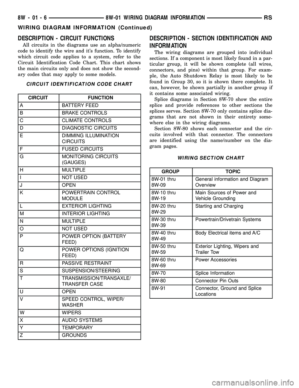
DESCRIPTION - CIRCUIT FUNCTIONS
All circuits in the diagrams use an alpha/numeric
code to identify the wire and it's function. To identify
which circuit code applies to a system, refer to the
Circuit Identification Code Chart. This chart shows
the main circuits only and does not show the second-
ary codes that may apply to some models.
CIRCUIT IDENTIFICATION CODE CHART
CIRCUIT FUNCTION
A BATTERY FEED
B BRAKE CONTROLS
C CLIMATE CONTROLS
D DIAGNOSTIC CIRCUITS
E DIMMING ILLUMINATION
CIRCUITS
F FUSED CIRCUITS
G MONITORING CIRCUITS
(GAUGES)
H MULTIPLE
I NOT USED
J OPEN
K POWERTRAIN CONTROL
MODULE
L EXTERIOR LIGHTING
M INTERIOR LIGHTING
N MULTIPLE
O NOT USED
P POWER OPTION (BATTERY
FEED)
Q POWER OPTIONS (IGNITION
FEED)
R PASSIVE RESTRAINT
S SUSPENSION/STEERING
T TRANSMISSION/TRANSAXLE/
TRANSFER CASE
U OPEN
V SPEED CONTROL, WIPER/
WASHER
W WIPERS
X AUDIO SYSTEMS
Y TEMPORARY
Z GROUNDS
DESCRIPTION - SECTION IDENTIFICATION AND
INFORMATION
The wiring diagrams are grouped into individual
sections. If a component is most likely found in a par-
ticular group, it will be shown complete (all wires,
connectors, and pins) within that group. For exam-
ple, the Auto Shutdown Relay is most likely to be
found in Group 30, so it is shown there complete. It
can, however, be shown partially in another group if
it contains some associated wiring.
Splice diagrams in Section 8W-70 show the entire
splice and provide references to other sections the
splices serves. Section 8W-70 only contains splice dia-
grams that are not shown in their entirety some-
where else in the wiring diagrams.
Section 8W-80 shows each connector and the cir-
cuits involved with that connector. The connectors
are identified using the name/number on the dia-
gram pages.
WIRING SECTION CHART
GROUP TOPIC
8W-01 thru
8W-09General information and Diagram
Overview
8W-10 thru
8W-19Main Sources of Power and
Vehicle Grounding
8W-20 thru
8W-29Starting and Charging
8W-30 thru
8W-39Powertrain/Drivetrain Systems
8W-40 thru
8W-49Body Electrical items and A/C
8W-50 thru
8W-59Exterior Lighting, Wipers and
Trailer Tow
8W-60 thru
8W-69Power Accessories
8W-70 Splice Information
8W-80 Connector Pin Outs
8W-91 Connector, Ground and Splice
Locations
8W - 01 - 6 8W-01 WIRING DIAGRAM INFORMATIONRS
WIRING DIAGRAM INFORMATION (Continued)
Page 1115 of 2339
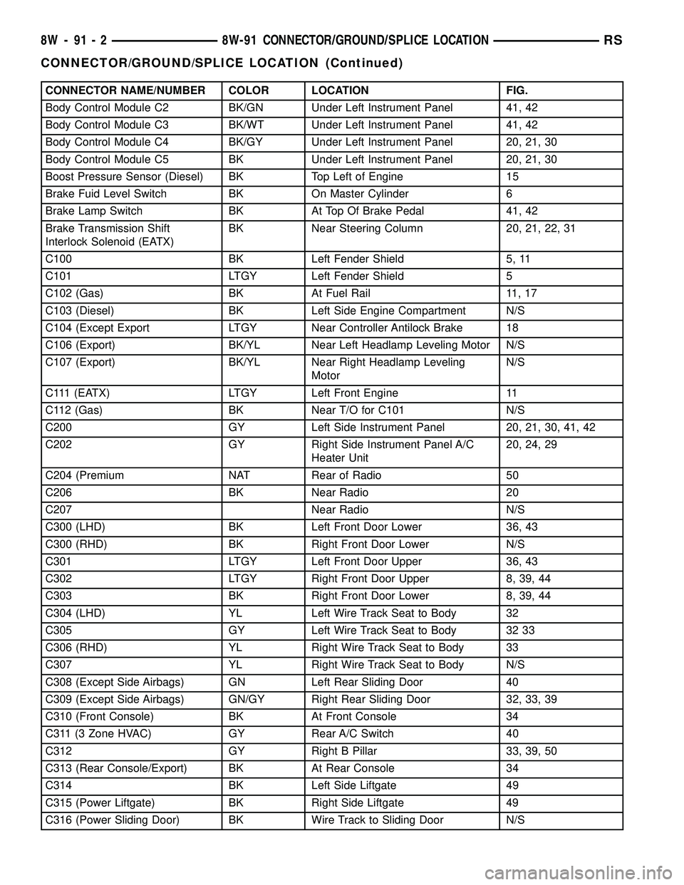
CONNECTOR NAME/NUMBER COLOR LOCATION FIG.
Body Control Module C2 BK/GN Under Left Instrument Panel 41, 42
Body Control Module C3 BK/WT Under Left Instrument Panel 41, 42
Body Control Module C4 BK/GY Under Left Instrument Panel 20, 21, 30
Body Control Module C5 BK Under Left Instrument Panel 20, 21, 30
Boost Pressure Sensor (Diesel) BK Top Left of Engine 15
Brake Fuid Level Switch BK On Master Cylinder 6
Brake Lamp Switch BK At Top Of Brake Pedal 41, 42
Brake Transmission Shift
Interlock Solenoid (EATX)BK Near Steering Column 20, 21, 22, 31
C100 BK Left Fender Shield 5, 11
C101 LTGY Left Fender Shield 5
C102 (Gas) BK At Fuel Rail 11, 17
C103 (Diesel) BK Left Side Engine Compartment N/S
C104 (Except Export LTGY Near Controller Antilock Brake 18
C106 (Export) BK/YL Near Left Headlamp Leveling Motor N/S
C107 (Export) BK/YL Near Right Headlamp Leveling
MotorN/S
C111 (EATX) LTGY Left Front Engine 11
C112 (Gas) BK Near T/O for C101 N/S
C200 GY Left Side Instrument Panel 20, 21, 30, 41, 42
C202 GY Right Side Instrument Panel A/C
Heater Unit20, 24, 29
C204 (Premium NAT Rear of Radio 50
C206 BK Near Radio 20
C207 Near Radio N/S
C300 (LHD) BK Left Front Door Lower 36, 43
C300 (RHD) BK Right Front Door Lower N/S
C301 LTGY Left Front Door Upper 36, 43
C302 LTGY Right Front Door Upper 8, 39, 44
C303 BK Right Front Door Lower 8, 39, 44
C304 (LHD) YL Left Wire Track Seat to Body 32
C305 GY Left Wire Track Seat to Body 32 33
C306 (RHD) YL Right Wire Track Seat to Body 33
C307 YL Right Wire Track Seat to Body N/S
C308 (Except Side Airbags) GN Left Rear Sliding Door 40
C309 (Except Side Airbags) GN/GY Right Rear Sliding Door 32, 33, 39
C310 (Front Console) BK At Front Console 34
C311 (3 Zone HVAC) GY Rear A/C Switch 40
C312 GY Right B Pillar 33, 39, 50
C313 (Rear Console/Export) BK At Rear Console 34
C314 BK Left Side Liftgate 49
C315 (Power Liftgate) BK Right Side Liftgate 49
C316 (Power Sliding Door) BK Wire Track to Sliding Door N/S
8W - 91 - 2 8W-91 CONNECTOR/GROUND/SPLICE LOCATIONRS
CONNECTOR/GROUND/SPLICE LOCATION (Continued)