Steering CHRYSLER VOYAGER 2005 Manual PDF
[x] Cancel search | Manufacturer: CHRYSLER, Model Year: 2005, Model line: VOYAGER, Model: CHRYSLER VOYAGER 2005Pages: 2339, PDF Size: 59.69 MB
Page 229 of 2339
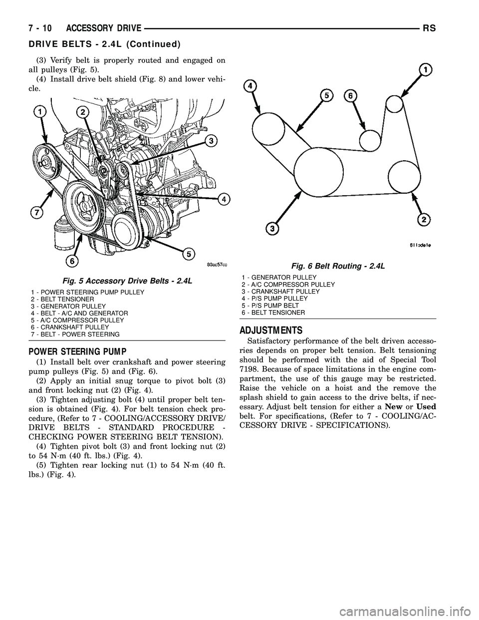
(3) Verify belt is properly routed and engaged on
all pulleys (Fig. 5).
(4) Install drive belt shield (Fig. 8) and lower vehi-
cle.
POWER STEERING PUMP
(1) Install belt over crankshaft and power steering
pump pulleys (Fig. 5) and (Fig. 6).
(2) Apply an initial snug torque to pivot bolt (3)
and front locking nut (2) (Fig. 4).
(3) Tighten adjusting bolt (4) until proper belt ten-
sion is obtained (Fig. 4). For belt tension check pro-
cedure, (Refer to 7 - COOLING/ACCESSORY DRIVE/
DRIVE BELTS - STANDARD PROCEDURE -
CHECKING POWER STEERING BELT TENSION).
(4) Tighten pivot bolt (3) and front locking nut (2)
to 54 N´m (40 ft. lbs.) (Fig. 4).
(5) Tighten rear locking nut (1) to 54 N´m (40 ft.
lbs.) (Fig. 4).
ADJUSTMENTS
Satisfactory performance of the belt driven accesso-
ries depends on proper belt tension. Belt tensioning
should be performed with the aid of Special Tool
7198. Because of space limitations in the engine com-
partment, the use of this gauge may be restricted.
Raise the vehicle on a hoist and the remove the
splash shield to gain access to the drive belts, if nec-
essary. Adjust belt tension for either aNeworUsed
belt. For specifications, (Refer to 7 - COOLING/AC-
CESSORY DRIVE - SPECIFICATIONS).
Fig. 5 Accessory Drive Belts - 2.4L
1 - POWER STEERING PUMP PULLEY
2 - BELT TENSIONER
3 - GENERATOR PULLEY
4 - BELT - A/C AND GENERATOR
5 - A/C COMPRESSOR PULLEY
6 - CRANKSHAFT PULLEY
7 - BELT - POWER STEERING
Fig. 6 Belt Routing - 2.4L
1 - GENERATOR PULLEY
2 - A/C COMPRESSOR PULLEY
3 - CRANKSHAFT PULLEY
4 - P/S PUMP PULLEY
5 - P/S PUMP BELT
6 - BELT TENSIONER
7 - 10 ACCESSORY DRIVERS
DRIVE BELTS - 2.4L (Continued)
Page 231 of 2339
INSTALLATION
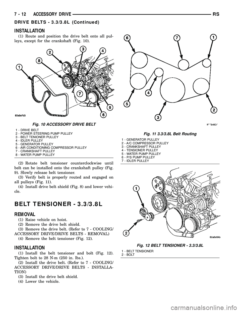
(1) Route and position the drive belt onto all pul-
leys, except for the crankshaft (Fig. 10).
(2) Rotate belt tensioner counterclockwise until
belt can be installed onto the crankshaft pulley (Fig.
9). Slowly release belt tensioner.
(3) Verify belt is properly routed and engaged on
all pulleys (Fig. 11).
(4) Install drive belt shield (Fig. 8) and lower vehi-
cle.
BELT TENSIONER - 3.3/3.8L
REMOVAL
(1) Raise vehicle on hoist.
(2) Remove the drive belt shield.
(3) Remove the drive belt. (Refer to 7 - COOLING/
ACCESSORY DRIVE/DRIVE BELTS - REMOVAL)
(4) Remove the belt tensioner (Fig. 12).
INSTALLATION
(1) Install the belt tensioner and bolt (Fig. 12).
Tighten bolt to 28 N´m (250 in. lbs.).
(2) Install the drive belt. (Refer to 7 - COOLING/
ACCESSORY DRIVE/DRIVE BELTS - INSTALLA-
TION)
(3) Install the drive belt shield.
(4) Lower the vehicle.
Fig. 10 ACCESSORY DRIVE BELT
1 - DRIVE BELT
2 - POWER STEERING PUMP PULLEY
3 - BELT TENIONER PULLEY
4 - IDLER PULLEY
5 - GENERATOR PULLEY
6 - AIR CONDITIONING COMPRESSOR PULLEY
7 - CRANKSHAFT PULLEY
8 - WATER PUMP PULLEY
Fig. 11 3.3/3.8L Belt Routing
1 - GENERATOR PULLEY
2 - A/C COMPRESSOR PULLEY
3 - CRANKSHAFT PULLEY
4 - TENSIONER PULLEY
5 - WATER PUMP PULLEY
6 - P/S PUMP PULLEY
7 - IDLER PULLEY
Fig. 12 BELT TENSIONER - 3.3/3.8L
1 - BELT TENSIONER
2 - BOLT
7 - 12 ACCESSORY DRIVERS
DRIVE BELTS - 3.3/3.8L (Continued)
Page 241 of 2339
(1) Drain cooling system below engine coolant tem-
perature sensor level. (Refer to 7 - COOLING -
STANDARD PROCEDURE)
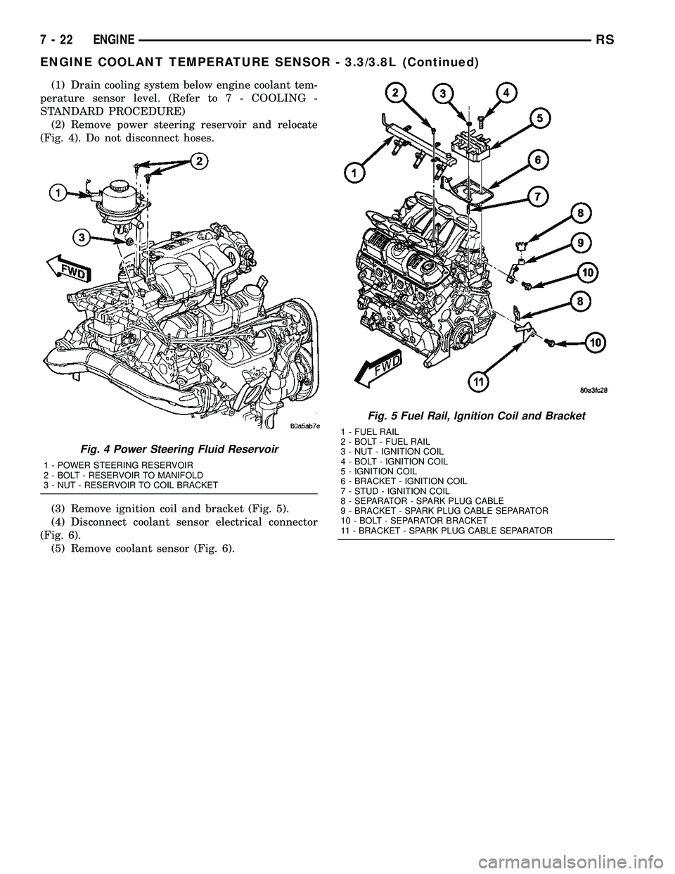
(2) Remove power steering reservoir and relocate
(Fig. 4). Do not disconnect hoses.
(3) Remove ignition coil and bracket (Fig. 5).
(4) Disconnect coolant sensor electrical connector
(Fig. 6).
(5) Remove coolant sensor (Fig. 6).
Fig. 4 Power Steering Fluid Reservoir
1 - POWER STEERING RESERVOIR
2 - BOLT - RESERVOIR TO MANIFOLD
3 - NUT - RESERVOIR TO COIL BRACKET
Fig. 5 Fuel Rail, Ignition Coil and Bracket
1 - FUEL RAIL
2 - BOLT - FUEL RAIL
3 - NUT - IGNITION COIL
4 - BOLT - IGNITION COIL
5 - IGNITION COIL
6 - BRACKET - IGNITION COIL
7 - STUD - IGNITION COIL
8 - SEPARATOR - SPARK PLUG CABLE
9 - BRACKET - SPARK PLUG CABLE SEPARATOR
10 - BOLT - SEPARATOR BRACKET
11 - BRACKET - SPARK PLUG CABLE SEPARATOR
7 - 22 ENGINERS
ENGINE COOLANT TEMPERATURE SENSOR - 3.3/3.8L (Continued)
Page 242 of 2339
INSTALLATION
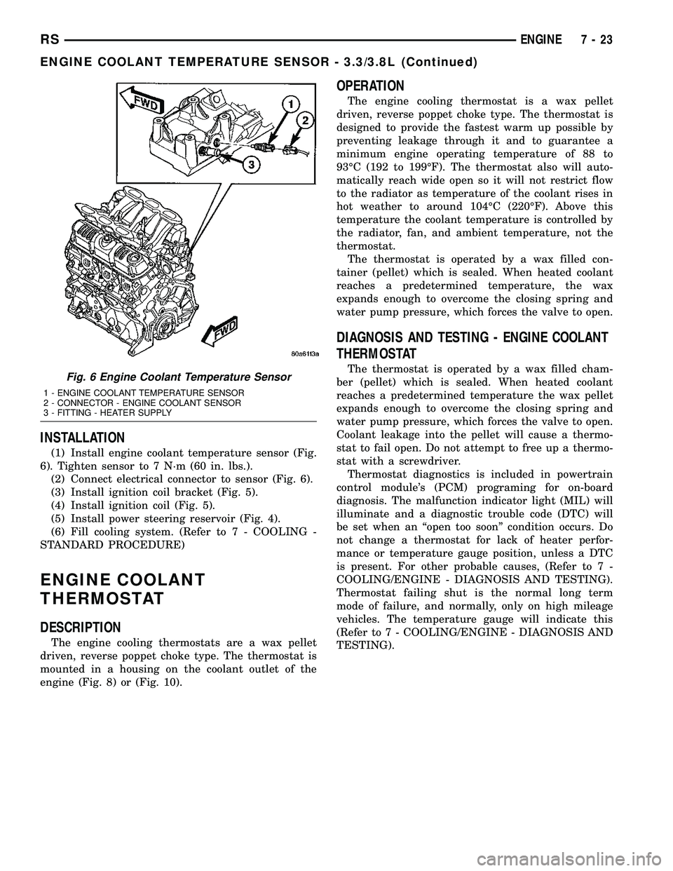
(1) Install engine coolant temperature sensor (Fig.
6). Tighten sensor to 7 N´m (60 in. lbs.).
(2) Connect electrical connector to sensor (Fig. 6).
(3) Install ignition coil bracket (Fig. 5).
(4) Install ignition coil (Fig. 5).
(5) Install power steering reservoir (Fig. 4).
(6) Fill cooling system. (Refer to 7 - COOLING -
STANDARD PROCEDURE)
ENGINE COOLANT
THERMOSTAT
DESCRIPTION
The engine cooling thermostats are a wax pellet
driven, reverse poppet choke type. The thermostat is
mounted in a housing on the coolant outlet of the
engine (Fig. 8) or (Fig. 10).
OPERATION
The engine cooling thermostat is a wax pellet
driven, reverse poppet choke type. The thermostat is
designed to provide the fastest warm up possible by
preventing leakage through it and to guarantee a
minimum engine operating temperature of 88 to
93ÉC (192 to 199ÉF). The thermostat also will auto-
matically reach wide open so it will not restrict flow
to the radiator as temperature of the coolant rises in
hot weather to around 104ÉC (220ÉF). Above this
temperature the coolant temperature is controlled by
the radiator, fan, and ambient temperature, not the
thermostat.
The thermostat is operated by a wax filled con-
tainer (pellet) which is sealed. When heated coolant
reaches a predetermined temperature, the wax
expands enough to overcome the closing spring and
water pump pressure, which forces the valve to open.
DIAGNOSIS AND TESTING - ENGINE COOLANT
THERMOSTAT
The thermostat is operated by a wax filled cham-
ber (pellet) which is sealed. When heated coolant
reaches a predetermined temperature the wax pellet
expands enough to overcome the closing spring and
water pump pressure, which forces the valve to open.
Coolant leakage into the pellet will cause a thermo-
stat to fail open. Do not attempt to free up a thermo-
stat with a screwdriver.
Thermostat diagnostics is included in powertrain
control module's (PCM) programing for on-board
diagnosis. The malfunction indicator light (MIL) will
illuminate and a diagnostic trouble code (DTC) will
be set when an ªopen too soonº condition occurs. Do
not change a thermostat for lack of heater perfor-
mance or temperature gauge position, unless a DTC
is present. For other probable causes, (Refer to 7 -
COOLING/ENGINE - DIAGNOSIS AND TESTING).
Thermostat failing shut is the normal long term
mode of failure, and normally, only on high mileage
vehicles. The temperature gauge will indicate this
(Refer to 7 - COOLING/ENGINE - DIAGNOSIS AND
TESTING).Fig. 6 Engine Coolant Temperature Sensor
1 - ENGINE COOLANT TEMPERATURE SENSOR
2 - CONNECTOR - ENGINE COOLANT SENSOR
3 - FITTING - HEATER SUPPLY
RSENGINE7-23
ENGINE COOLANT TEMPERATURE SENSOR - 3.3/3.8L (Continued)
Page 258 of 2339
TRANSMISSION OIL COOLER
DESCRIPTION
The automatic transmission cooler is located in the
front of the radiator and behind the front fascia and
is conbined with the A/C condensor. The transmission
cooler is a heat exchanger that allows heat in the
transmission flud to be transferred to the air passing
over the cooler fins.
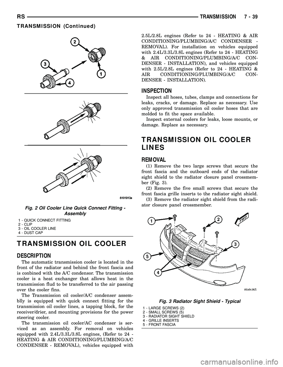
The Transmission oil cooler/A/C condenser assem-
blly is equipped with quick connect fitting for the
transmission oil cooler lines, a tapping block, for the
receiver/drier, and mounting provisions for the power
steering cooler.
The transmission oil cooler/AC condenser is ser-
viced as an assembly. For removal on vehicles
equipped with 2.4L/3.3L/3.8L engines, (Refer to 24 -
HEATING & AIR CONDITIONING/PLUMBING/A/C
CONDENSER - REMOVAL), vehicles equipped with2.5L/2.8L engines (Refer to 24 - HEATING & AIR
CONDITIONING/PLUMBING/A/C CONDENSER -
REMOVAL). For installation on vehicles equipped
with 2.4L/3.3L/3.8L engines (Refer to 24 - HEATING
& AIR CONDITIONING/PLUMBING/A/C CON-
DENSER - INSTALLATION), and vehicles equipped
with 2.5L/2.8L engines (Refer to 24 - HEATING &
AIR CONDITIONING/PLUMBING/A/C CON-
DENSER - INSTALLATION).
INSPECTION
Inspect all hoses, tubes, clamps and connections for
leaks, cracks, or damage. Replace as necessary. Use
only approved transmission oil cooler hoses that are
molded to fit the space available.
Inspect external coolers for leaks, loose mounts, or
damage. Replace as necessary.
TRANSMISSION OIL COOLER
LINES
REMOVAL
(1) Remove the two large screws that secure the
front fascia and the outboard ends of the radiator
sight shield to the radiator closure panel crossmem-
ber (Fig. 3).
(2) Remove the five small screws that secure the
front fascia grille inserts to the radiator sight shield.
(3) Remove the radiator sight shield from the radi-
ator closure panel crossmember.
Fig. 2 Oil Cooler Line Quick Connect Fitting -
Assembly
1 - QUICK CONNECT FITTING
2 - CLIP
3 - OIL COOLER LINE
4 - DUST CAP
Fig. 3 Radiator Sight Shield - Typical
1 - LARGE SCREWS (2)
2 - SMALL SCREWS (5)
3 - RADIATOR SIGHT SHIELD
4 - GRILLE INSERTS
5 - FRONT FASCIA
RSTRANSMISSION7-39
TRANSMISSION (Continued)
Page 261 of 2339
mation. For diagnosis of these electronic modules or
of the data bus network, the use of a DRB IIItscan
tool and the proper Diagnostic Procedures informa-
tion is recommended.
DIAGNOSIS AND TESTING
AUDIO/VIDEO
Any diagnosis of the Audio system should
begin with the use of the DRB IIItdiagnostic
tool. For information on the use of the DRBIIIt, refer to the appropriate Diagnostic Service
information.
Refer to the appropriate wiring information.
WARNING: ON VEHICLES EQUIPPED WITH AIR-
BAGS, REFER TO ELECTRICAL, RESTRAINTS
BEFORE ATTEMPTING ANY STEERING WHEEL,
STEERING COLUMN, OR INSTRUMENT PANEL
COMPONENT DIAGNOSIS OR SERVICE. FAILURE
TO TAKE THE PROPER PRECAUTIONS COULD
RESULT IN ACCIDENTAL AIRBAG DEPLOYMENT
AND POSSIBLE PERSONAL INJURY.
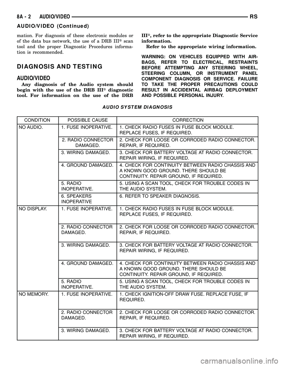
AUDIO SYSTEM DIAGNOSIS
CONDITION POSSIBLE CAUSE CORRECTION
NO AUDIO. 1. FUSE INOPERATIVE. 1. CHECK RADIO FUSES IN FUSE BLOCK MODULE.
REPLACE FUSES, IF REQUIRED.
2. RADIO CONNECTOR
DAMAGED.2. CHECK FOR LOOSE OR CORRODED RADIO CONNECTOR.
REPAIR, IF REQUIRED.
3. WIRING DAMAGED. 3. CHECK FOR BATTERY VOLTAGE AT RADIO CONNECTOR.
REPAIR WIRING, IF REQUIRED.
4. GROUND DAMAGED. 4. CHECK FOR CONTINUITY BETWEEN RADIO CHASSIS AND
A KNOWN GOOD GROUND. THERE SHOULD BE
CONTINUITY. REPAIR GROUND, IF REQUIRED.
5. RADIO
INOPERATIVE.5. USING A SCAN TOOL, CHECK FOR TROUBLE CODES IN
THE AUDIO SYSTEM.
6. SPEAKERS
INOPERATIVE6. REFER TO SPEAKER DIAGNOSIS.
NO DISPLAY. 1. FUSE INOPERATIVE. 1. CHECK RADIO FUSES IN FUSE BLOCK MODULE.
REPLACE FUSES, IF REQUIRED.
2. RADIO CONNECTOR
DAMAGED.2. CHECK FOR LOOSE OR CORRODED RADIO CONNECTOR.
REPAIR, IF REQUIRED.
3. WIRING DAMAGED. 3. CHECK FOR BATTERY VOLTAGE AT RADIO CONNECTOR.
REPAIR WIRING, IF REQUIRED.
4. GROUND DAMAGED. 4. CHECK FOR CONTINUITY BETWEEN RADIO CHASSIS AND
A KNOWN GOOD GROUND. THERE SHOULD BE
CONTINUITY. REPAIR GROUND, IF REQUIRED.
5. RADIO
INOPERATIVE.5. USING A SCAN TOOL, CHECK FOR TROUBLE CODES IN
THE AUDIO SYSTEM.
NO MEMORY. 1. FUSE INOPERATIVE. 1. CHECK IGNITION-OFF DRAW FUSE. REPLACE FUSE, IF
REQUIRED.
2. RADIO CONNECTOR
DAMAGED.2. CHECK FOR LOOSE OR CORRODED RADIO CONNECTOR.
REPAIR, IF REQUIRED.
3. WIRING DAMAGED. 3. CHECK FOR BATTERY VOLTAGE AT RADIO CONNECTOR.
REPAIR WIRING, IF REQUIRED.
8A - 2 AUDIO/VIDEORS
AUDIO/VIDEO (Continued)
Page 267 of 2339
DIAGNOSIS AND TESTING
ANTENNA BODY AND CABLE
WARNING: ON VEHICLES EQUIPPED WITH AIR-
BAGS, REFER TO ELECTRICAL, RESTRAINTS
BEFORE ATTEMPTING ANY STEERING WHEEL,
STEERING COLUMN, OR INSTRUMENT PANEL
COMPONENT DIAGNOSIS OR SERVICE. FAILURE
TO TAKE THE PROPER PRECAUTIONS COULD
RESULT IN ACCIDENTAL AIRBAG DEPLOYMENT
AND POSSIBLE PERSONAL INJURY.
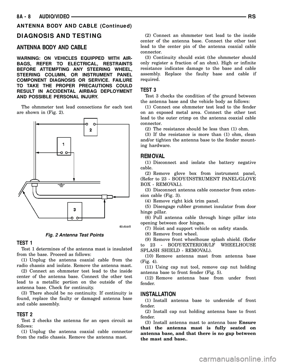
The ohmmeter test lead connections for each test
are shown in (Fig. 2).
TEST 1
Test 1 determines of the antenna mast is insulated
from the base. Proceed as follows:
(1) Unplug the antenna coaxial cable from the
radio chassis and isolate. Remove the antenna mast.
(2) Connect an ohmmeter test lead to the inside
center of the antenna base. Connect the other test
lead to a metallic portion on the outside of the
antenna base. Check for continuity.
(3) There should be no continuity. If continuity is
found, replace the faulty or damaged antenna base
and cable assembly.
TEST 2
Test 2 checks the antenna for an open circuit as
follows:
(1) Unplug the antenna coaxial cable connector
from the radio chassis. Remove the antenna mast.(2) Connect an ohmmeter test lead to the inside
center of the antenna base. Connect the other test
lead to the center pin of the antenna coaxial cable
connector.
(3) Continuity should exist (the ohmmeter should
only register a fraction of an ohm). High or infinite
resistance indicates damage to the base and cable
assembly. Replace the faulty base and cable if
required.
TEST 3
Test 3 checks the condition of the ground between
the antenna base and the vehicle body as follows:
(1) Connect one ohmmeter test lead to the fender
on an exposed metal area. Connect the other test
lead to the outer crimp on the antenna coaxial cable
connector.
(2) The resistance should be less than (1) ohm.
(3) If the resistance is more than (1) ohm, clean
and/or tighten the antenna base to the fender mount-
ing hardware.
REMOVAL
(1) Disconnect and isolate the battery negative
cable.
(2) Remove glove box from instrument panel,
(Refer to 23 - BODY/INSTRUMENT PANEL/GLOVE
BOX - REMOVAL).
(3) Disconnect antenna cable connector from exten-
sion cable (Fig. 3).
(4) Remove right kick trim panel.
(5) Disengage rubber grommet insulator from door
hinge pillar.
(6) Pull antenna cable through hinge pillar into
opening between door hinges.
(7) Hoist and support vehicle on safety stands.
(8) Remove front wheel.
(9) Remove front wheelhouse splash shield. (Refer
to 23 - BODY/EXTERIOR/LF WHEELHOUSE
SPLASH SHIELD - REMOVAL).
(10) Remove antenna mast from antenna base
(Fig. 4).
(11) Using cap nut tool, remove cap nut holding
antenna base to front fender (Fig. 5).
(12) Remove antenna base from under front
fender.
INSTALLATION
(1) Install antenna base to underside of front
fender.
(2) Install cap nut holding antenna base to front
fender.
(3) Install antenna mast to antenna baseEnsure
that the antenna mast is fully seated on
antenna base, and that there is no gap between
the mast and base..
Fig. 2 Antenna Test Points
8A - 8 AUDIO/VIDEORS
ANTENNA BODY AND CABLE (Continued)
Page 271 of 2339
(3) Install screws holding CD changer.
(4) Reconnect the battery negative cable.
DVD PLAYER
DESCRIPTION
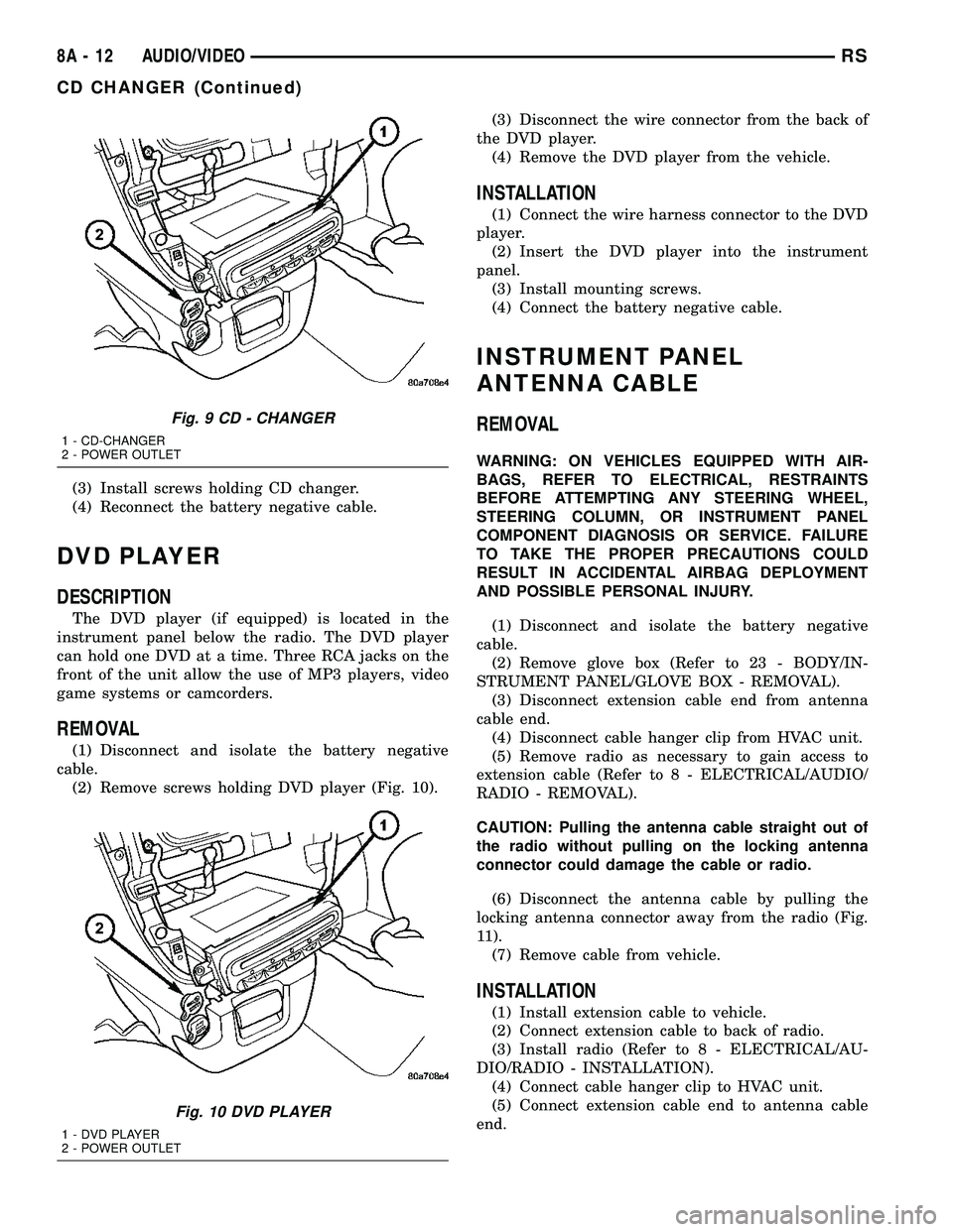
The DVD player (if equipped) is located in the
instrument panel below the radio. The DVD player
can hold one DVD at a time. Three RCA jacks on the
front of the unit allow the use of MP3 players, video
game systems or camcorders.
REMOVAL
(1) Disconnect and isolate the battery negative
cable.
(2) Remove screws holding DVD player (Fig. 10).(3) Disconnect the wire connector from the back of
the DVD player.
(4) Remove the DVD player from the vehicle.
INSTALLATION
(1) Connect the wire harness connector to the DVD
player.
(2) Insert the DVD player into the instrument
panel.
(3) Install mounting screws.
(4) Connect the battery negative cable.
INSTRUMENT PANEL
ANTENNA CABLE
REMOVAL
WARNING: ON VEHICLES EQUIPPED WITH AIR-
BAGS, REFER TO ELECTRICAL, RESTRAINTS
BEFORE ATTEMPTING ANY STEERING WHEEL,
STEERING COLUMN, OR INSTRUMENT PANEL
COMPONENT DIAGNOSIS OR SERVICE. FAILURE
TO TAKE THE PROPER PRECAUTIONS COULD
RESULT IN ACCIDENTAL AIRBAG DEPLOYMENT
AND POSSIBLE PERSONAL INJURY.
(1) Disconnect and isolate the battery negative
cable.
(2) Remove glove box (Refer to 23 - BODY/IN-
STRUMENT PANEL/GLOVE BOX - REMOVAL).
(3) Disconnect extension cable end from antenna
cable end.
(4) Disconnect cable hanger clip from HVAC unit.
(5) Remove radio as necessary to gain access to
extension cable (Refer to 8 - ELECTRICAL/AUDIO/
RADIO - REMOVAL).
CAUTION: Pulling the antenna cable straight out of
the radio without pulling on the locking antenna
connector could damage the cable or radio.
(6) Disconnect the antenna cable by pulling the
locking antenna connector away from the radio (Fig.
11).
(7) Remove cable from vehicle.
INSTALLATION
(1) Install extension cable to vehicle.
(2) Connect extension cable to back of radio.
(3) Install radio (Refer to 8 - ELECTRICAL/AU-
DIO/RADIO - INSTALLATION).
(4) Connect cable hanger clip to HVAC unit.
(5) Connect extension cable end to antenna cable
end.
Fig. 9 CD - CHANGER
1 - CD-CHANGER
2 - POWER OUTLET
Fig. 10 DVD PLAYER
1 - DVD PLAYER
2 - POWER OUTLET
8A - 12 AUDIO/VIDEORS
CD CHANGER (Continued)
Page 273 of 2339
OPERATION
The radio receiver operates on ignition switched
battery current that is available only when the igni-
tion switch is in the On or Accessory/Accessory Delay
positions. The electronic digital clock function of the
radio operates on fused battery current supplied
through the IOD fuse, regardless of the ignition
switch position.
For complete circuit diagrams, refer to the appro-
priate wiring information.
DIAGNOSIS AND TESTING
RADIO
WARNING: ON VEHICLES EQUIPPED WITH AIR-
BAGS, REFER TO ELECTRICAL, RESTRAINTS
BEFORE ATTEMPTING ANY STEERING WHEEL,
STEERING COLUMN, OR INSTRUMENT PANEL
COMPONENT DIAGNOSIS OR SERVICE. FAILURE
TO TAKE THE PROPER PRECAUTIONS COULD
RESULT IN ACCIDENTAL AIRBAG DEPLOYMENT
AND POSSIBLE PERSONAL INJURY.
Any diagnosis of the Audio system should
begin with the use of the DRB IIItdiagnostic
tool. For information on the use of the DRB
IIIt, refer to the appropriate Diagnostic Service
Manual.
Refer to the appropriate wiring information.
If the vehicle is equipped with remote radio
switches located on the back of the steering wheel
spokes, and the problem being diagnosed is related to
one of the symptoms listed below, be certain to check
the remote radio switches and circuits as described
in this group, prior to attempting radio diagnosis or
repair.
²Stations changing with no remote radio switch
input
²Radio memory presets not working properly
²Volume changes with no remote radio switch
input
²Remote radio switch buttons taking on other
functions
²CD player skipping tracks
²Remote radio switch inoperative.
CAUTION: The speaker output of the radio is a
ªfloating groundº system. Do not allow any speaker
lead to short to ground, as damage to the radio
may result.
(1) Check the fuse(s) in the junction block and the
Integrated Power Module (IPM). If OK, go to Step 2.
If not OK, repair the shorted circuit or component as
required and replace the faulty fuse(s).(2) Check for battery voltage at the fuse in the
(IPM). If OK, go to Step 3. If not OK, repair the open
circuit to the battery as required.
(3) Turn the ignition switch to the ON position.
Check for battery voltage at the fuse in the junction
block. If OK, go to Step 4. If not OK, repair the open
circuit to the ignition switch as required.
(4) Turn the ignition switch to the OFF position.
Remove the radio, but do not unplug the wire har-
ness connectors. Check for continuity between the
radio chassis and a good ground. There should be
continuity. If OK, go to Step 5. If not OK, repair the
open radio chassis ground circuit as required.
(5) Connect the battery negative cable. Turn the
ignition switch to the ON position. Check for battery
voltage at the fused ignition switch output circuit
cavity of the radio wire harness connector. If OK, go
to Step 6. If not OK, repair the open circuit as
required.
(6) Turn the ignition switch to the OFF position.
Check for battery voltage at the fused B(+) circuit
cavity of the radio wire harness connector. If OK,
replace the faulty radio. If not OK, repair the open
circuit to the Ignition-Off Draw (IOD) fuse as
required.
REMOVAL
(1) Disconnect and isolate the battery negative
cable.
(2) Remove cup holder.
(3) Remove trim panel above cupholder by pulling
straight out.
(4) Remove center instrument panel trim panel.
(5) Remove screws holding radio to instrument
panel.
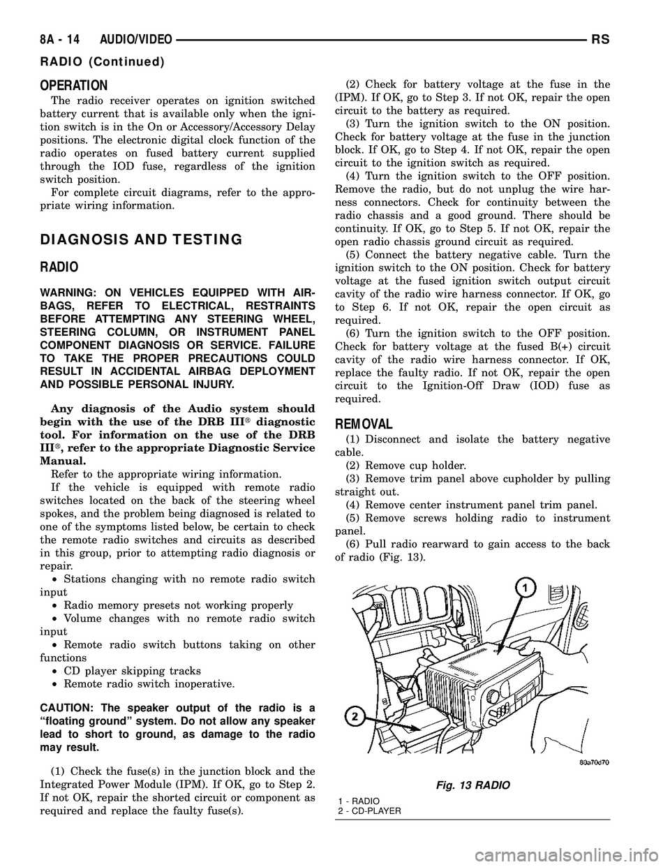
(6) Pull radio rearward to gain access to the back
of radio (Fig. 13).
Fig. 13 RADIO
1 - RADIO
2 - CD-PLAYER
8A - 14 AUDIO/VIDEORS
RADIO (Continued)
Page 275 of 2339
REMOTE SWITCHES
DESCRIPTION
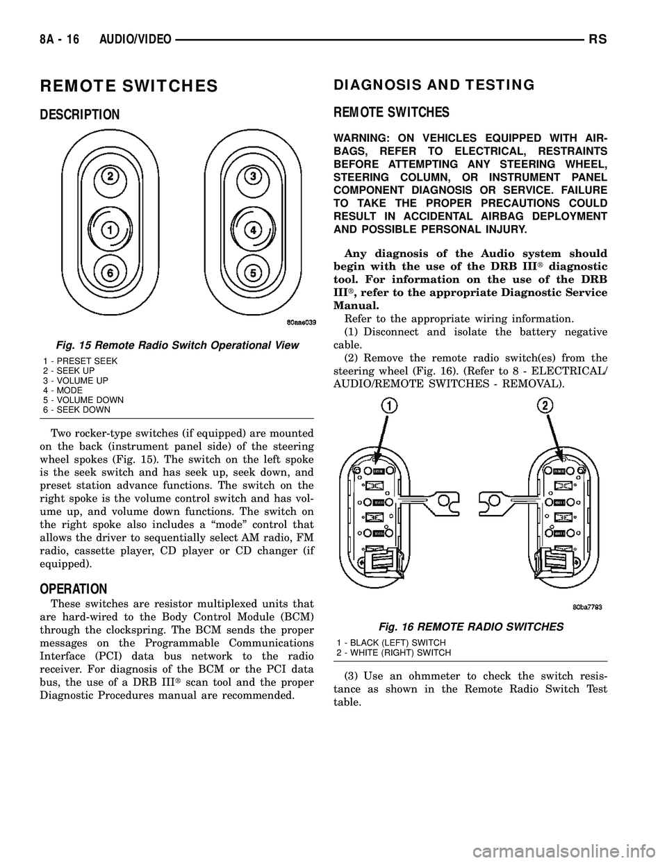
Two rocker-type switches (if equipped) are mounted
on the back (instrument panel side) of the steering
wheel spokes (Fig. 15). The switch on the left spoke
is the seek switch and has seek up, seek down, and
preset station advance functions. The switch on the
right spoke is the volume control switch and has vol-
ume up, and volume down functions. The switch on
the right spoke also includes a ªmodeº control that
allows the driver to sequentially select AM radio, FM
radio, cassette player, CD player or CD changer (if
equipped).
OPERATION
These switches are resistor multiplexed units that
are hard-wired to the Body Control Module (BCM)
through the clockspring. The BCM sends the proper
messages on the Programmable Communications
Interface (PCI) data bus network to the radio
receiver. For diagnosis of the BCM or the PCI data
bus, the use of a DRB IIItscan tool and the proper
Diagnostic Procedures manual are recommended.
DIAGNOSIS AND TESTING
REMOTE SWITCHES
WARNING: ON VEHICLES EQUIPPED WITH AIR-
BAGS, REFER TO ELECTRICAL, RESTRAINTS
BEFORE ATTEMPTING ANY STEERING WHEEL,
STEERING COLUMN, OR INSTRUMENT PANEL
COMPONENT DIAGNOSIS OR SERVICE. FAILURE
TO TAKE THE PROPER PRECAUTIONS COULD
RESULT IN ACCIDENTAL AIRBAG DEPLOYMENT
AND POSSIBLE PERSONAL INJURY.
Any diagnosis of the Audio system should
begin with the use of the DRB IIItdiagnostic
tool. For information on the use of the DRB
IIIt, refer to the appropriate Diagnostic Service
Manual.
Refer to the appropriate wiring information.
(1) Disconnect and isolate the battery negative
cable.
(2) Remove the remote radio switch(es) from the
steering wheel (Fig. 16). (Refer to 8 - ELECTRICAL/
AUDIO/REMOTE SWITCHES - REMOVAL).
(3) Use an ohmmeter to check the switch resis-
tance as shown in the Remote Radio Switch Test
table.
Fig. 15 Remote Radio Switch Operational View
1 - PRESET SEEK
2 - SEEK UP
3 - VOLUME UP
4 - MODE
5 - VOLUME DOWN
6 - SEEK DOWN
Fig. 16 REMOTE RADIO SWITCHES
1 - BLACK (LEFT) SWITCH
2 - WHITE (RIGHT) SWITCH
8A - 16 AUDIO/VIDEORS