CHRYSLER VOYAGER 2005 Service Manual
Manufacturer: CHRYSLER, Model Year: 2005, Model line: VOYAGER, Model: CHRYSLER VOYAGER 2005Pages: 2339, PDF Size: 59.69 MB
Page 151 of 2339
CAUTION: When tightening the primary and sec-
ondary brake tube nuts at master cylinder, be sure
brake tubes do not contact any other components
within the vehicle and that there is slack in the flex-
ible sections of the tubes. This is required due to
the movement between the ABS ICU and the master
cylinder while the vehicle is in motion.
(4) Connect primary and secondary brake tubes to
master cylinder primary and secondary ports (Fig.
50). Brake tubes must be held securely when tight-
ened to control orientation of flex section. Tighten
tube nuts to a torque of 17 N´m (145 in. lbs.).
(5) Install wiring harness connector to brake fluid
level switch mounted in brake fluid reservoir (Fig.
46).
(6) Install battery, clamp and nut.
(7) Install battery shield.
(8) Connect positive battery terminal.
(9) Connect negative battery terminal.
(10) Fill master cylinder with clean, fresh Mopart
Brake Fluid or equivalent.
(11) Road test vehicle to ensure proper operation of
brakes.
PEDALS - ADJUSTABLE
REMOVAL
NOTE: Before proceeding, review all Steering Col-
umn and Airbag Warnings and Cautions. (Refer to
19 - STEERING/COLUMN - WARNING)(Refer to 8 -
ELECTRICAL/RESTRAINTS - WARNING)
(1) Move driver's seat to full rearward position.
(2) Disconnect negative battery cable from battery
post and isolate.
(3) Remove throttle cable from throttle body lever.
(Refer to 14 - FUEL SYSTEM/FUEL INJECTION/
THROTTLE CONTROL CABLE - REMOVAL)
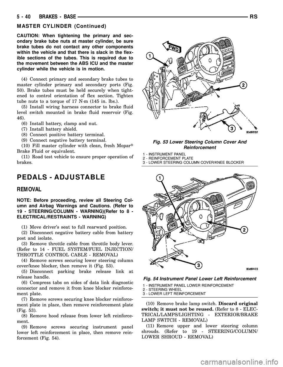
(4) Remove screws securing lower steering column
cover/knee blocker, then remove it (Fig. 53).
(5) Disconnect parking brake release link at
release handle.
(6) Compress tabs on sides of data link diagnostic
connector and remove it from knee blocker reinforce-
ment plate.
(7) Remove screws securing knee blocker reinforce-
ment plate in place, then remove reinforcement plate
(Fig. 53).
(8) Remove hood release from lower left reinforce-
ment.
(9) Remove screws securing instrument panel
lower left reinforcement in place, then remove rein-
forcement (Fig. 54).(10) Remove brake lamp switch.Discard original
switch; it must not be reused.(Refer to 8 - ELEC-
TRICAL/LAMPS/LIGHTING - EXTERIOR/BRAKE
LAMP SWITCH - REMOVAL)
(11) Remove upper and lower steering column
shrouds. (Refer to 19 - STEERING/COLUMN/
LOWER SHROUD - REMOVAL)
Fig. 53 Lower Steering Column Cover And
Reinforcement
1 - INSTRUMENT PANEL
2 - REINFORCEMENT PLATE
3 - LOWER STEERING COLUMN COVER/KNEE BLOCKER
Fig. 54 Instrument Panel Lower Left Reinforcement
1 - INSTRUMENT PANEL LOWER REINFORCEMENT
2 - STEERING WHEEL
3 - LOWER LEFT REINFORCEMENT
5 - 40 BRAKES - BASERS
MASTER CYLINDER (Continued)
Page 152 of 2339
(12) Disconnect wiring harness connectors (as
equipped) from clockspring, multi-function switch,
SKIM module, ignition switch and BTSI solenoid.
(13) If equipped, disconnect PRNDL cable from
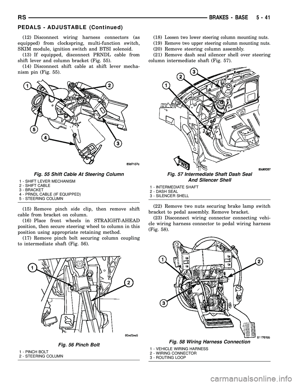
shift lever and column bracket (Fig. 55).
(14) Disconnect shift cable at shift lever mecha-
nism pin (Fig. 55).
(15) Remove pinch side clip, then remove shift
cable from bracket on column.
(16) Place front wheels in STRAIGHT-AHEAD
position, then secure steering wheel to column in this
position using appropriate retaining method.
(17) Remove pinch bolt securing column coupling
to intermediate shaft (Fig. 56).(18)Loosen two lower steering column mounting nuts.
(19)Remove two upper steering column mounting nuts.
(20) Remove steering column assembly.
(21) Remove dash seal silencer shell over steering
column intermediate shaft (Fig. 57).
(22) Remove two nuts securing brake lamp switch
bracket to pedal assembly. Remove bracket.
(23) Disconnect wiring connector connecting vehi-
cle wiring harness connector to pedal wiring harness
(Fig. 58).
Fig. 55 Shift Cable At Steering Column
1 - SHIFT LEVER MECHANISM
2 - SHIFT CABLE
3 - BRACKET
4 - PRNDL CABLE (IF EQUIPPED)
5 - STEERING COLUMN
Fig. 56 Pinch Bolt
1 - PINCH BOLT
2 - STEERING COLUMN
Fig. 57 Intermediate Shaft Dash Seal
And Silencer Shell
1 - INTERMEDIATE SHAFT
2 - DASH SEAL
3 - SILENCER SHELL
Fig. 58 Wiring Harness Connection
1 - VEHICLE WIRING HARNESS
2 - WIRING CONNECTOR
3 - ROUTING LOOP
RSBRAKES - BASE5-41
PEDALS - ADJUSTABLE (Continued)
Page 153 of 2339

(24) Unfasten routing clips retaining vehicle wir-
ing harness to pedal wiring harness (Fig. 58).
(25) Remove power brake booster input rod from
brake pedal pin by performing following:
(a) Position small screwdriver between center
tang on retaining clip and brake pedal pin (Fig.
59).
(b) Rotate screwdriver, moving retaining clip
center tang enough to allow it to pass over end of
brake pedal pin, then slide retaining clip off brake
pedal pin.
(c) Discard retaining clip.Retaining clip must
not be reused. Install NEW retaining clip
when assembling.
(d) Slide booster input rod off pedal pin.
(26) Disconnect pedal adjuster cable at brake
pedal adjustment gear box (Fig. 60).
(27) Remove pedal adjuster cable from routing loop
on steering column bracket (Fig. 60), then pull gear
box end of cable upward, out of steering column
bracket, and down right side of pedals assembly.
(28) Remove four nuts attaching power brake
booster and pedals assembly to dash panel (Fig. 61).
(29) Remove two upper mounting bolts attaching
pedals assembly to steering column support bracket
on dash.
(30) Disconnect throttle cable retainer at accelera-
tor pedal, then remove cable from pedal.
(31) Remove adjustable pedals assembly.
Fig. 59 Input Rod Brake Pedal Retaining Clip
Removal
1 - BRAKE PEDAL
2 - INPUT ROD
3 - SCREWDRIVER
4 - RETAINING CLIP
5 - BRAKE PEDAL PIN
Fig. 60 Drive Cable Routing
1 - ADJUSTER CABLE
2 - ROUTING LOOP
3 - CABLE ATTACHMENT AT MOTOR
4 - GEAR DRIVE
5 - CABLE ATTACHMENT AT GEAR BOX
6 - STEERING COLUMN BRACKET
Fig. 61 Booster Mounting (Typical)
1 - DASH BRACKET
2 - POWER BRAKE BOOSTER
3 - BRAKE PEDAL ASSEMBLY
5 - 42 BRAKES - BASERS
PEDALS - ADJUSTABLE (Continued)
Page 154 of 2339
INSTALLATION
(1) Install adjustable pedals assembly under
instrument panel.
(2) Attach throttle cable to accelerator pedal using
cable retainer.
(3) Install two upper mounting bolts attaching
pedals assembly to steering column support bracket
on dash panel.Do not fully tighten at this time.
(4) Install four nuts attaching pedals assembly and
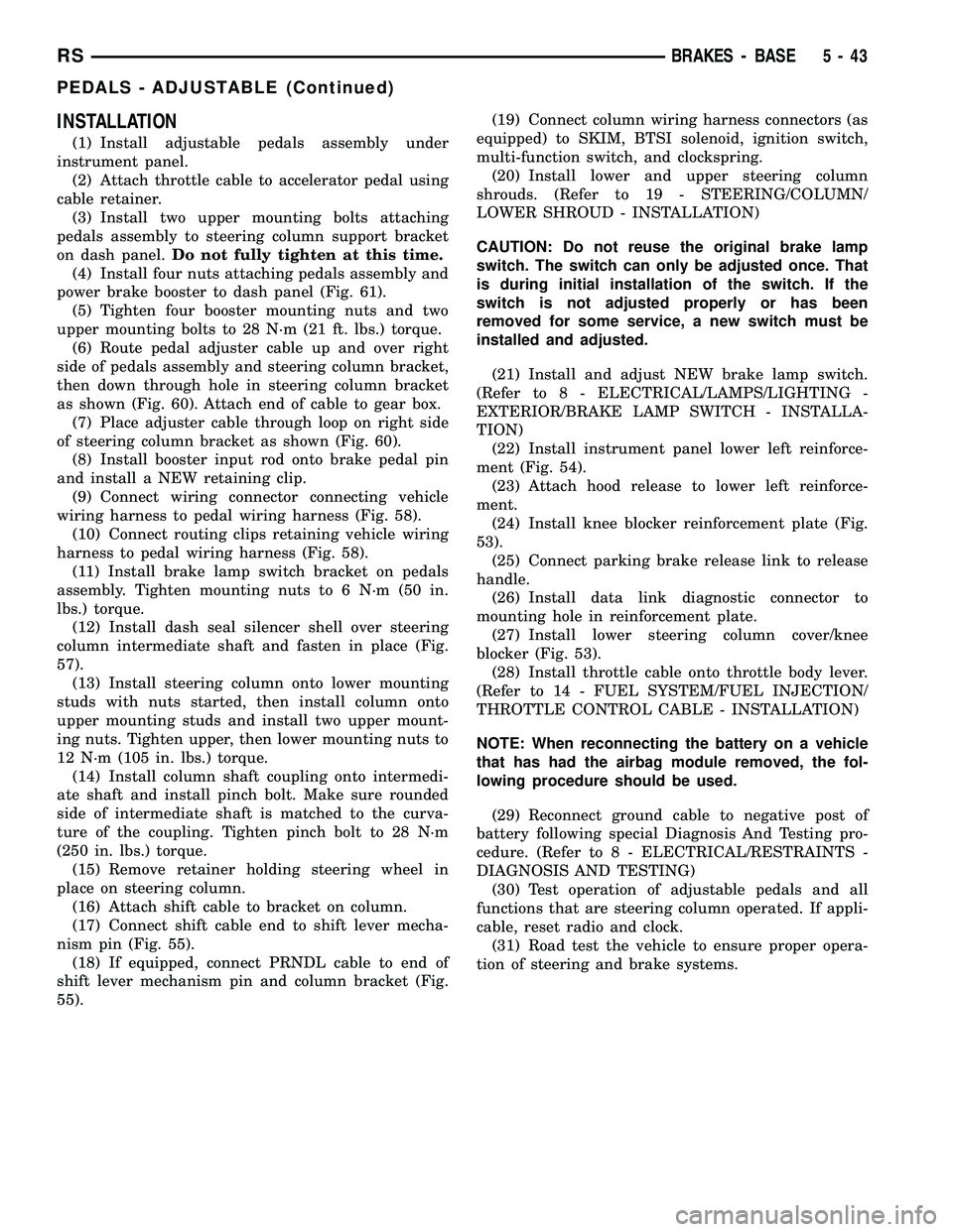
power brake booster to dash panel (Fig. 61).
(5) Tighten four booster mounting nuts and two
upper mounting bolts to 28 N´m (21 ft. lbs.) torque.
(6) Route pedal adjuster cable up and over right
side of pedals assembly and steering column bracket,
then down through hole in steering column bracket
as shown (Fig. 60). Attach end of cable to gear box.
(7) Place adjuster cable through loop on right side
of steering column bracket as shown (Fig. 60).
(8) Install booster input rod onto brake pedal pin
and install a NEW retaining clip.
(9) Connect wiring connector connecting vehicle
wiring harness to pedal wiring harness (Fig. 58).
(10) Connect routing clips retaining vehicle wiring
harness to pedal wiring harness (Fig. 58).
(11) Install brake lamp switch bracket on pedals
assembly. Tighten mounting nuts to 6 N´m (50 in.
lbs.) torque.
(12) Install dash seal silencer shell over steering
column intermediate shaft and fasten in place (Fig.
57).
(13) Install steering column onto lower mounting
studs with nuts started, then install column onto
upper mounting studs and install two upper mount-
ing nuts. Tighten upper, then lower mounting nuts to
12 N´m (105 in. lbs.) torque.
(14) Install column shaft coupling onto intermedi-
ate shaft and install pinch bolt. Make sure rounded
side of intermediate shaft is matched to the curva-
ture of the coupling. Tighten pinch bolt to 28 N´m
(250 in. lbs.) torque.
(15) Remove retainer holding steering wheel in
place on steering column.
(16) Attach shift cable to bracket on column.
(17) Connect shift cable end to shift lever mecha-
nism pin (Fig. 55).
(18) If equipped, connect PRNDL cable to end of
shift lever mechanism pin and column bracket (Fig.
55).(19) Connect column wiring harness connectors (as
equipped) to SKIM, BTSI solenoid, ignition switch,
multi-function switch, and clockspring.
(20) Install lower and upper steering column
shrouds. (Refer to 19 - STEERING/COLUMN/
LOWER SHROUD - INSTALLATION)
CAUTION: Do not reuse the original brake lamp
switch. The switch can only be adjusted once. That
is during initial installation of the switch. If the
switch is not adjusted properly or has been
removed for some service, a new switch must be
installed and adjusted.
(21) Install and adjust NEW brake lamp switch.
(Refer to 8 - ELECTRICAL/LAMPS/LIGHTING -
EXTERIOR/BRAKE LAMP SWITCH - INSTALLA-
TION)
(22) Install instrument panel lower left reinforce-
ment (Fig. 54).
(23) Attach hood release to lower left reinforce-
ment.
(24) Install knee blocker reinforcement plate (Fig.
53).
(25) Connect parking brake release link to release
handle.
(26) Install data link diagnostic connector to
mounting hole in reinforcement plate.
(27) Install lower steering column cover/knee
blocker (Fig. 53).
(28) Install throttle cable onto throttle body lever.
(Refer to 14 - FUEL SYSTEM/FUEL INJECTION/
THROTTLE CONTROL CABLE - INSTALLATION)
NOTE: When reconnecting the battery on a vehicle
that has had the airbag module removed, the fol-
lowing procedure should be used.
(29) Reconnect ground cable to negative post of
battery following special Diagnosis And Testing pro-
cedure. (Refer to 8 - ELECTRICAL/RESTRAINTS -
DIAGNOSIS AND TESTING)
(30) Test operation of adjustable pedals and all
functions that are steering column operated. If appli-
cable, reset radio and clock.
(31) Road test the vehicle to ensure proper opera-
tion of steering and brake systems.
RSBRAKES - BASE5-43
PEDALS - ADJUSTABLE (Continued)
Page 155 of 2339
PEDAL TORQUE SHAFT - RHD
REMOVAL
(1) Remove the instrument panel. (Refer to 23 -
BODY/INSTRUMENT PANEL/INSTRUMENT
PANEL ASSEMBLY - REMOVAL)
(2) Remove the HVAC housing. (Refer to 24 -
HEATING & AIR CONDITIONING/DISTRIBUTION/
HVAC HOUSING - REMOVAL)
(3) Remove the retaining clip at the torque shaft
end of the brake pedal-to-torque shaft link. Remove
the link from the torque shaft. Discard the retaining
clip. It is not to be reused. Replace with a new clip
when reassembled.
(4) Locate the booster input rod-to-brake pedal
torque shaft connection and remove the retaining clip
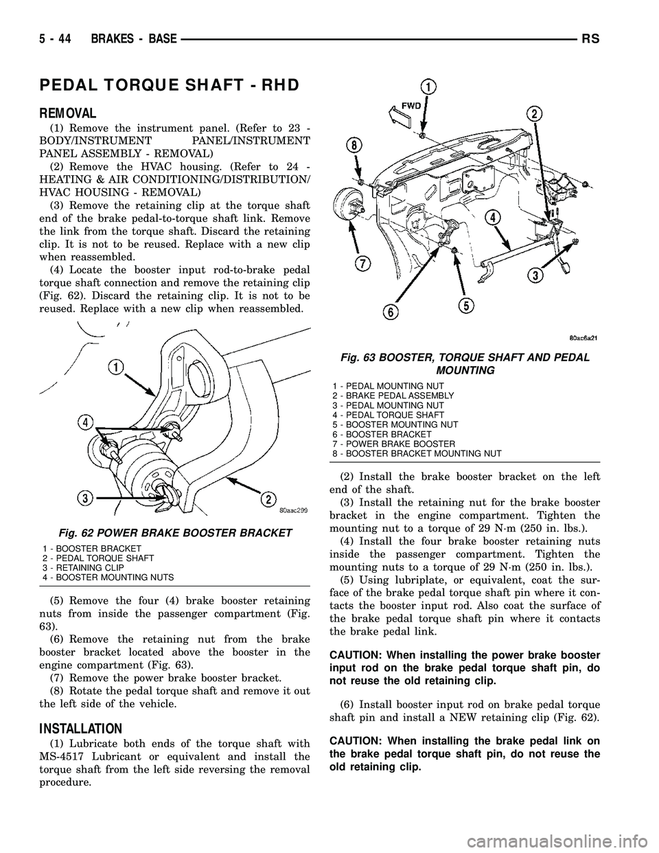
(Fig. 62). Discard the retaining clip. It is not to be
reused. Replace with a new clip when reassembled.
(5) Remove the four (4) brake booster retaining
nuts from inside the passenger compartment (Fig.
63).
(6) Remove the retaining nut from the brake
booster bracket located above the booster in the
engine compartment (Fig. 63).
(7) Remove the power brake booster bracket.
(8) Rotate the pedal torque shaft and remove it out
the left side of the vehicle.
INSTALLATION
(1) Lubricate both ends of the torque shaft with
MS-4517 Lubricant or equivalent and install the
torque shaft from the left side reversing the removal
procedure.(2) Install the brake booster bracket on the left
end of the shaft.
(3) Install the retaining nut for the brake booster
bracket in the engine compartment. Tighten the
mounting nut to a torque of 29 N´m (250 in. lbs.).
(4) Install the four brake booster retaining nuts
inside the passenger compartment. Tighten the
mounting nuts to a torque of 29 N´m (250 in. lbs.).
(5) Using lubriplate, or equivalent, coat the sur-
face of the brake pedal torque shaft pin where it con-
tacts the booster input rod. Also coat the surface of
the brake pedal torque shaft pin where it contacts
the brake pedal link.
CAUTION: When installing the power brake booster
input rod on the brake pedal torque shaft pin, do
not reuse the old retaining clip.
(6) Install booster input rod on brake pedal torque
shaft pin and install a NEW retaining clip (Fig. 62).
CAUTION: When installing the brake pedal link on
the brake pedal torque shaft pin, do not reuse the
old retaining clip.
Fig. 62 POWER BRAKE BOOSTER BRACKET
1 - BOOSTER BRACKET
2 - PEDAL TORQUE SHAFT
3 - RETAINING CLIP
4 - BOOSTER MOUNTING NUTS
Fig. 63 BOOSTER, TORQUE SHAFT AND PEDAL
MOUNTING
1 - PEDAL MOUNTING NUT
2 - BRAKE PEDAL ASSEMBLY
3 - PEDAL MOUNTING NUT
4 - PEDAL TORQUE SHAFT
5 - BOOSTER MOUNTING NUT
6 - BOOSTER BRACKET
7 - POWER BRAKE BOOSTER
8 - BOOSTER BRACKET MOUNTING NUT
5 - 44 BRAKES - BASERS
Page 156 of 2339
(7) Connect the brake pedal link to the torque
shaft. Install a NEW retaining clip at the torque
shaft end of the brake pedal-to-torque shaft link.
(8) Install the HVAC housing. (Refer to 24 - HEAT-
ING & AIR CONDITIONING/DISTRIBUTION/HVAC
HOUSING - INSTALLATION)
(9) Install the instrument panel. (Refer to 23 -
BODY/INSTRUMENT PANEL/INSTRUMENT
PANEL ASSEMBLY - INSTALLATION)
CAUTION: Do not reuse the original brake lamp
switch. The switch can only be adjusted once. That
is during initial installation of the switch. If the
switch is not adjusted properly or has been
removed for some service, a new switch must be
installed and adjusted.
(10) Remove and replace the brake lamp switch
with a NEW switch. (Refer to 8 - ELECTRICAL/
LAMPS/LIGHTING - EXTERIOR/BRAKE LAMP
SWITCH - REMOVAL), (Refer to 8 - ELECTRICAL/
LAMPS/LIGHTING - EXTERIOR/BRAKE LAMP
SWITCH - INSTALLATION)
(11) Road test vehicle to ensure proper operation of
the brakes.
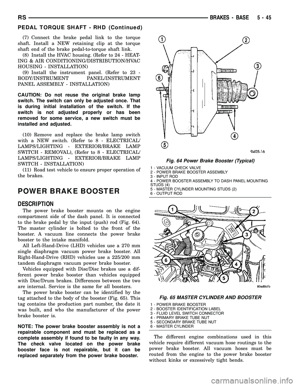
POWER BRAKE BOOSTER
DESCRIPTION
The power brake booster mounts on the engine
compartment side of the dash panel. It is connected
to the brake pedal by the input (push) rod (Fig. 64).
The master cylinder is bolted to the front of the
booster. A vacuum line connects the power brake
booster to the intake manifold.
All Left-Hand-Drive (LHD) vehicles use a 270 mm
single diaphragm vacuum power brake booster. All
Right-Hand-Drive (RHD) vehicles use a 225/200 mm
tandem diaphragm vacuum power brake booster.
Vehicles equipped with Disc/Disc brakes use a dif-
ferent power brake booster than vehicles equipped
with Disc/Drum brakes. Differences between the two
are internal. Service is the same for all boosters.
The power brake booster can be identified by the
tag attached to the body of the booster (Fig. 65). This
tag contains the production part number, the date it
was built, and who the manufacturer of the power
brake booster is.
NOTE: The power brake booster assembly is not a
repairable component and must be replaced as a
complete assembly if found to be faulty in any way.
The check valve located on the power brake
booster face is not repairable, but it can be
replaced separately from the power brake booster.The different engine combinations used in this
vehicle require different vacuum hose routings to the
power brake booster. All vacuum hoses must be
routed from the engine to the power brake booster
without kinks or excessively tight bends.
Fig. 64 Power Brake Booster (Typical)
1 - VACUUM CHECK VALVE
2 - POWER BRAKE BOOSTER ASSEMBLY
3 - INPUT ROD
4 - POWER BOOSTER ASSEMBLY TO DASH PANEL MOUNTING
STUDS (4)
5 - MASTER CYLINDER MOUNTING STUDS (2)
6 - OUTPUT ROD
Fig. 65 MASTER CYLINDER AND BOOSTER
1 - POWER BRAKE BOOSTER
2 - BOOSTER IDENTIFICATION LABEL
3 - FLUID LEVEL SWITCH CONNECTOR
4 - PRIMARY BRAKE TUBE NUT
5 - SECONDARY BRAKE TUBE NUT
6 - MASTER CYLINDER
RSBRAKES - BASE5-45
PEDAL TORQUE SHAFT - RHD (Continued)
Page 157 of 2339

OPERATION
The power brake booster reduces the amount of
force required by the driver to obtain the necessary
hydraulic pressure to stop a vehicle.
The power brake booster is vacuum operated. The
vacuum is supplied from the intake manifold on the
engine through a vacuum hose and the power brake
booster check valve (Fig. 64).
As the brake pedal is depressed, the power brake
booster's input rod moves forward (Fig. 64). This
opens and closes valves in the power booster allowing
atmospheric pressure to enter on one side of a dia-
phragm. Engine vacuum is always present on the
other side. This difference in pressure forces the out-
put rod of the power brake booster out against the
primary piston of the master cylinder. As the pistons
in the master cylinder move forward this creates the
hydraulic pressure in the brake system.
DIAGNOSIS AND TESTING - POWER BRAKE
BOOSTER
BASIC TEST
(1) With engine off, depress and release the brake
pedal several times to purge all vacuum from the
power brake booster.
(2) Depress and hold the pedal with light effort (15
to 25 lbs. pressure), then start the engine.
The pedal should fall slightly, then hold. Less effort
should be needed to apply the pedal at this time. If
the pedal fell as indicated, perform the VACUUM
LEAK TEST listed after the BASIC TEST. If the
pedal did not fall, continue on with this BASIC
TEST.
(3) Disconnect the vacuum hose on the vacuum
check valve, then place a vacuum gauge in line
between the vacuum hose and the valve.
(4) Start the engine.
(5) When the engine is at warm operating temper-
ature, allow it to idle and check the vacuum at the
gauge.
If the vacuum supply is 12 inches Hg (40.5 kPa) or
more, the power brake booster is defective and must
be replaced. If the vacuum supply is below 12 inches
Hg, continue on with this BASIC TEST.
(6) Shut off the engine.
(7) Connect the vacuum gauge to the vacuum ref-
erence port on the engine intake manifold.
(8) Start the engine and observe the vacuum
gauge.
If the vacuum is still low, check the engine tune
and repair as necessary. If the vacuum is above 12
inches Hg, the hose or check valve to the booster has
a restriction or leak.
Once an adequate vacuum supply is obtained,
repeat the BASIC TEST.
VACUUM LEAK TEST
(1) Disconnect the vacuum hose on the vacuum
check valve, then place a vacuum gauge in line
between the vacuum hose and the valve.
(2) Start the engine.
(3) Allow the engine to warm up to normal operat-
ing temperature and engine idle.
(4) Using vacuum line pliers, close off the vacuum
supply hose near the booster, but before the vacuum
gauge, then observe the vacuum gauge.
If the vacuum drop exceeds 1.0 inch Hg (3.3 kPa)
in one minute, repeat the above steps to confirm the
reading. The vacuum loss should be less than 1.0
inch Hg in one minute time span. If the loss is more
than 1.0 inch Hg, replace the power brake booster. If
it is not, continue on with this test.
(5) Remove the pliers from the hose temporarily.
(6) Apply light effort (approximately 15 lbs. of
force) to the brake pedal and hold the pedal steady.
Do not move the pedal once the pressure is applied
or the test results may vary.
(7) Have an assistant reattach the vacuum line
pliers to the vacuum supply hose.
(8) Allow 5 seconds for stabilization, then observe
the vacuum gauge.
If the vacuum drop exceeds 3.0 inches Hg (10 kPa)
in 15 seconds, repeat the above steps to confirm the
reading. The vacuum loss should be less than 3.0
inches Hg in 15 seconds time span. If the loss is
more than 3.0 inches Hg, replace the power brake
booster. If it is not, the booster is not defective.
(9) Remove the pliers and vacuum gauge.
REMOVAL
REMOVAL - LHD
CAUTION: Reserve vacuum in power brake booster
must be pumped down (removed) before removing
master cylinder from booster. This is necessary to
prevent booster from sucking in any contamination
as master cylinder is removed. This can be done
simply by pumping the brake pedal, with the vehi-
cle's engine not running, until a firm feeling brake
pedal is achieved.
(1) With engine not running, pump the brake
pedal until a firm pedal is achieved (4-5 strokes).
(2) Remove negative battery cable terminal from
battery.
(3) Remove positive battery cable terminal from
battery.
(4) Remove battery thermal guard shield.
(5) Remove battery clamp, nut and battery from
the battery tray.
5 - 46 BRAKES - BASERS
POWER BRAKE BOOSTER (Continued)
Page 158 of 2339

(6) Remove screw securing engine coolant filler
tube to battery tray.
(7) If the vehicle is equipped with speed control,
disconnect the vacuum hose at the vacuum tank built
into the battery tray.
(8) Remove the two nuts and one bolt securing bat-
tery tray in place. Remove battery tray.
(9) If vehicle is equipped with speed control:
(a) Disconnect wiring harness connector from
the speed control servo.
(b) Remove the two servo mounting nuts.
(c) Lay speed control servo off to the side, out of
the way.
(10) Remove the wiper module (unit). (Refer to 8 -
ELECTRICAL/WIPERS/WASHERS/WIPER MOD-
ULE - REMOVAL)
(11) Disconnect wiring harness connector from
brake fluid level switch in master cylinder fluid res-
ervoir (Fig. 66).
CAUTION: Before removing the master cylinder
from the power brake vacuum booster, the master
cylinder and vacuum booster must be thoroughly
cleaned. This must be done to prevent dirt particles
from falling into the power brake vacuum booster.
(12) Clean area where master cylinder assembly
attaches to power brake booster. Use only a solvent
such as MopartBrake Parts Cleaner or equivalent.(13) Disconnect primary and secondary brake
tubes from ABS integrated control unit or non-ABS
junction block (Fig. 67). Install sealing plugs in the
now open brake tube ports and install caps on ends
of tubes.
NOTE: It is not necessary to remove the brake
tubes from the master cylinder when removing the
master cylinder from the vacuum booster.
(14) Remove two nuts attaching master cylinder to
power brake booster (Fig. 67).
(15) Slide master cylinder straight out of power
brake booster. Remove master cylinder with primary
and secondary tubes from vehicle.
CAUTION: A seal on the rear of the master cylinder
is used to create the seal for holding vacuum in the
power brake vacuum booster. The vacuum seal on
the master cylinder MUST be replaced whenever the
master cylinder is removed from the power brake
vacuum booster.
(16) Disconnect vacuum hose from check valve
located on vacuum booster.DO NOT REMOVE
CHECK VALVE FROM POWER BRAKE
BOOSTER.
Fig. 66 Master Cylinder And Booster
1 - POWER BRAKE BOOSTER
2 - BOOSTER IDENTIFICATION LABEL
3 - FLUID LEVEL SWITCH CONNECTOR
4 - PRIMARY BRAKE TUBE NUT
5 - SECONDARY BRAKE TUBE NUT
6 - MASTER CYLINDER
Fig. 67 Master Cylinder Mounting
1 - MASTER CYLINDER MOUNTING NUTS
2 - MASTER CYLINDER
3 - SECONDARY TUBE NUT AT ICU
4 - PRIMARY TUBE NUT AT ICU
RSBRAKES - BASE5-47
POWER BRAKE BOOSTER (Continued)
Page 159 of 2339
(17) Inside vehicle, remove silencer panel under
instrument panel below steering column.
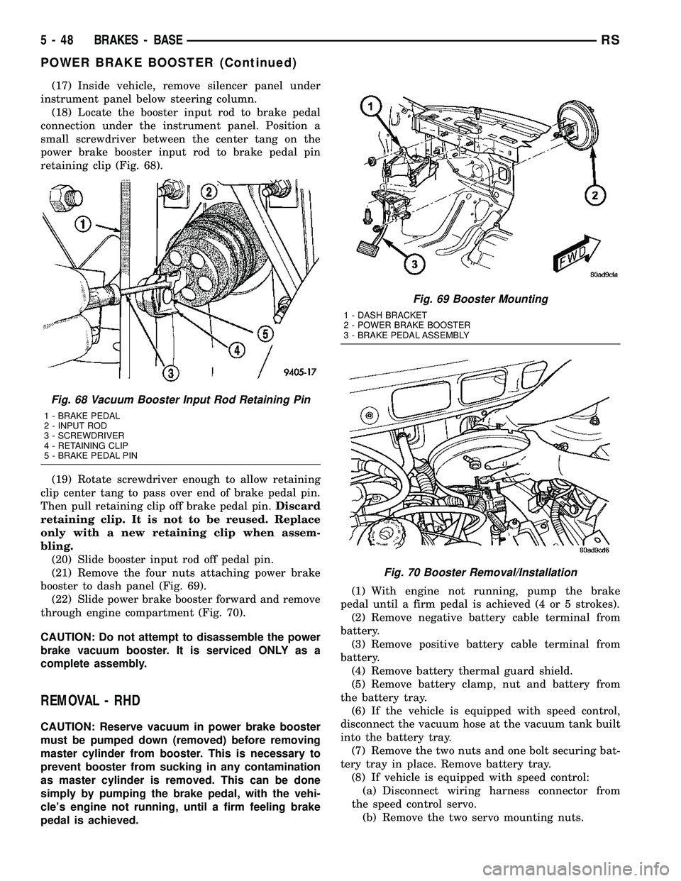
(18) Locate the booster input rod to brake pedal
connection under the instrument panel. Position a
small screwdriver between the center tang on the
power brake booster input rod to brake pedal pin
retaining clip (Fig. 68).
(19) Rotate screwdriver enough to allow retaining
clip center tang to pass over end of brake pedal pin.
Then pull retaining clip off brake pedal pin.Discard
retaining clip. It is not to be reused. Replace
only with a new retaining clip when assem-
bling.
(20) Slide booster input rod off pedal pin.
(21) Remove the four nuts attaching power brake
booster to dash panel (Fig. 69).
(22) Slide power brake booster forward and remove
through engine compartment (Fig. 70).
CAUTION: Do not attempt to disassemble the power
brake vacuum booster. It is serviced ONLY as a
complete assembly.
REMOVAL - RHD
CAUTION: Reserve vacuum in power brake booster
must be pumped down (removed) before removing
master cylinder from booster. This is necessary to
prevent booster from sucking in any contamination
as master cylinder is removed. This can be done
simply by pumping the brake pedal, with the vehi-
cle's engine not running, until a firm feeling brake
pedal is achieved.(1) With engine not running, pump the brake
pedal until a firm pedal is achieved (4 or 5 strokes).
(2) Remove negative battery cable terminal from
battery.
(3) Remove positive battery cable terminal from
battery.
(4) Remove battery thermal guard shield.
(5) Remove battery clamp, nut and battery from
the battery tray.
(6) If the vehicle is equipped with speed control,
disconnect the vacuum hose at the vacuum tank built
into the battery tray.
(7) Remove the two nuts and one bolt securing bat-
tery tray in place. Remove battery tray.
(8) If vehicle is equipped with speed control:
(a) Disconnect wiring harness connector from
the speed control servo.
(b) Remove the two servo mounting nuts.
Fig. 68 Vacuum Booster Input Rod Retaining Pin
1 - BRAKE PEDAL
2 - INPUT ROD
3 - SCREWDRIVER
4 - RETAINING CLIP
5 - BRAKE PEDAL PIN
Fig. 69 Booster Mounting
1 - DASH BRACKET
2 - POWER BRAKE BOOSTER
3 - BRAKE PEDAL ASSEMBLY
Fig. 70 Booster Removal/Installation
5 - 48 BRAKES - BASERS
POWER BRAKE BOOSTER (Continued)
Page 160 of 2339
(c) Lay speed control servo off to the side, out of
the way.
(9) If the vehicle is equipped with the 2.5L diesel
engine, remove the coolant recovery pressure con-
tainer and bracket. (Refer to 7 - COOLING/ENGINE/
COOLANT RECOVERY PRESS CONTAINER -
REMOVAL)
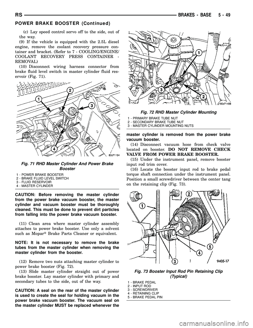
(10) Disconnect wiring harness connector from
brake fluid level switch in master cylinder fluid res-
ervoir (Fig. 71).
CAUTION: Before removing the master cylinder
from the power brake vacuum booster, the master
cylinder and vacuum booster must be thoroughly
cleaned. This must be done to prevent dirt particles
from falling into the power brake vacuum booster.
(11) Clean area where master cylinder assembly
attaches to power brake booster. Use only a solvent
such as MopartBrake Parts Cleaner or equivalent.
NOTE: It is not necessary to remove the brake
tubes from the master cylinder when removing the
master cylinder from the booster.
(12) Remove two nuts attaching master cylinder to
power brake booster (Fig. 72).
(13) Slide master cylinder straight out of power
brake booster. Lay master cylinder with primary and
secondary tubes to the side, out of the way.
CAUTION: A seal on the rear of the master cylinder
is used to create the seal for holding vacuum in the
power brake vacuum booster. The vacuum seal on
the master cylinder MUST be replaced whenever themaster cylinder is removed from the power brake
vacuum booster.
(14) Disconnect vacuum hose from check valve
located on booster.DO NOT REMOVE CHECK
VALVE FROM POWER BRAKE BOOSTER.
(15) Under the instrument panel, remove booster
input rod trim cover.
(16) Locate the booster input rod to brake pedal
torque shaft connection under the instrument panel.
Position a small screwdriver between the center tang
on the retaining clip (Fig. 73).
Fig. 71 RHD Master Cylinder And Power Brake
Booster
1 - POWER BRAKE BOOSTER
2 - BRAKE FLUID LEVEL SWITCH
3 - FLUID RESERVOIR
4 - MASTER CYLINDER
Fig. 72 RHD Master Cylinder Mounting
1 - PRIMARY BRAKE TUBE NUT
2 - SECONDARY BRAKE TUBE NUT
3 - MASTER CYLINDER MOUNTING NUTS
Fig. 73 Booster Input Rod Pin Retaining Clip
(Typical)
1 - BRAKE PEDAL
2 - INPUT ROD
3 - SCREWDRIVER
4 - RETAINING CLIP
5 - BRAKE PEDAL PIN
RSBRAKES - BASE5-49
POWER BRAKE BOOSTER (Continued)