CHRYSLER VOYAGER 2005 Service Manual
Manufacturer: CHRYSLER, Model Year: 2005, Model line: VOYAGER, Model: CHRYSLER VOYAGER 2005Pages: 2339, PDF Size: 59.69 MB
Page 181 of 2339

CABLE - PARKING BRAKE
REAR
REMOVAL
REMOVAL - RIGHT REAR
(1) Raise and support the vehicle. (Refer to
LUBRICATION & MAINTENANCE/HOISTING -
STANDARD PROCEDURE).
(2) Remove rear tire and wheel assembly.
(3) Remove rear brake drum from the rear wheel
of the vehicle requiring service to the rear park
brake cable.
(4) Create slack in the rear parking brake cables
by locking out the automatic adjuster as described
here. Grasp an exposed section of front parking
brake cable near the equalizer and pull down on it.
At this time install a pair of locking pliers on the
cable just rearward of the second body outrigger
bracket (Fig. 110).(5) Disconnect the right rear parking brake cable
from the connector on the intermediate cable (Fig.
111).
(6) To remove the right parking brake cable hous-
ing from the body bracket, slide a 14 mm box end
wrench over the end of cable retainer to compress the
retaining fingers (Fig. 112). The alternate method
using an aircraft type hose clamp will not work on
the right side of the vehicle.
Fig. 110 Locking Out Automatic Adjuster
1 - PARK BRAKE CABLE
2 - REAR BODY OUTRIGGER BRACKET
3 - LOCKING PLIERS
Fig. 111 Right Rear Cable Connection To
Intermediate Cable
1 - RIGHT REAR PARKING BRAKE CABLE
2 - LOCKING NUT
3 - INTERMEDIATE PARKING BRAKE CABLE
Fig. 112 Right Park Brake Cable Removal From
Body Bracket
1 - RIGHT REAR BODY BRACKET
2 - PARK BRAKE CABLE
3 - 14MM WRENCH
4 - LEAF SPRING AND BRACKET
5 - 70 BRAKES - BASERS
Page 182 of 2339

(7) Remove the brake shoes from the brake sup-
port plate. (Refer to 5 - BRAKES/HYDRAULIC/ME-
CHANICAL/BRAKE PADS/SHOES - REMOVAL).
(8) Disconnect parking brake cable from parking
brake actuator lever.
(9) Remove the parking brake cable housing
retainer from the brake support plate using a 14mm
wrench to compress the retaining fingers (Fig. 113).
Remove the cable.
REMOVAL - LEFT REAR
(1) Raise and support the vehicle. (Refer to
LUBRICATION & MAINTENANCE/HOISTING -
STANDARD PROCEDURE)
(2) Remove rear tire and wheel assembly.
(3) Remove rear brake drum from the rear wheel
of the vehicle requiring service to the rear park
brake cable.
(4) Create slack in rear park brake cables by lock-
ing out the automatic adjuster as described here.
Grasp an exposed section of front park brake cable
near the equalizer and pull down on it. Then install
a pair of locking pliers on the cable just rearward of
the second body outrigger bracket (Fig. 114).
(5) Disconnect the left rear parking brake cable
from the parking brake cable equalizer (Fig. 115).
Fig. 113 Removing Park Brake Cable From Brake
Support Plate
1 - PARK BRAKE CABLE RETAINER
2 - PARK BRAKE CABLE
3 - 14MM BOX WRENCH
4 - BRAKE SUPPORT PLATE
Fig. 114 Locked Out Park Brake Automatic Adjuster
1 - PARK BRAKE CABLE
2 - REAR BODY OUTRIGGER BRACKET
3 - LOCKING PLIERS
Fig. 115 Parking Brake Cables At Equalizer
1 - EQUALIZER
2 - LEFT REAR PARKING BRAKE CABLE
3 - LOCKING NUT
4 - INTERMEDIATE PARKING BRAKE CABLE
5 - FRONT PARKING BRAKE CABLE
RSBRAKES - BASE5-71
CABLE - PARKING BRAKE REAR (Continued)
Page 183 of 2339

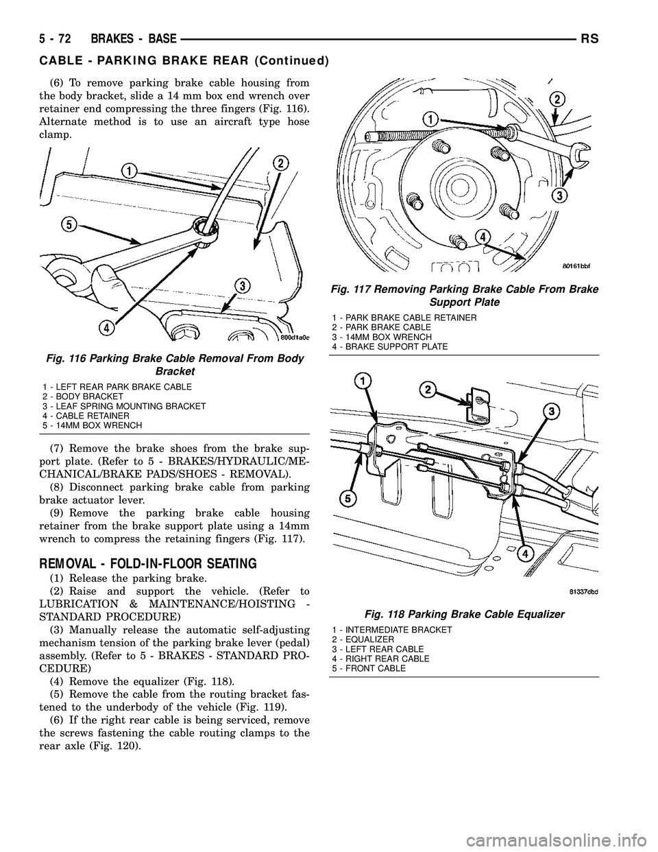
(6) To remove parking brake cable housing from
the body bracket, slide a 14 mm box end wrench over
retainer end compressing the three fingers (Fig. 116).
Alternate method is to use an aircraft type hose
clamp.
(7) Remove the brake shoes from the brake sup-
port plate. (Refer to 5 - BRAKES/HYDRAULIC/ME-
CHANICAL/BRAKE PADS/SHOES - REMOVAL).
(8) Disconnect parking brake cable from parking
brake actuator lever.
(9) Remove the parking brake cable housing
retainer from the brake support plate using a 14mm
wrench to compress the retaining fingers (Fig. 117).
REMOVAL - FOLD-IN-FLOOR SEATING
(1) Release the parking brake.
(2) Raise and support the vehicle. (Refer to
LUBRICATION & MAINTENANCE/HOISTING -
STANDARD PROCEDURE)
(3) Manually release the automatic self-adjusting
mechanism tension of the parking brake lever (pedal)
assembly. (Refer to 5 - BRAKES - STANDARD PRO-
CEDURE)
(4) Remove the equalizer (Fig. 118).
(5) Remove the cable from the routing bracket fas-
tened to the underbody of the vehicle (Fig. 119).
(6) If the right rear cable is being serviced, remove
the screws fastening the cable routing clamps to the
rear axle (Fig. 120).
Fig. 116 Parking Brake Cable Removal From Body
Bracket
1 - LEFT REAR PARK BRAKE CABLE
2 - BODY BRACKET
3 - LEAF SPRING MOUNTING BRACKET
4 - CABLE RETAINER
5 - 14MM BOX WRENCH
Fig. 117 Removing Parking Brake Cable From Brake
Support Plate
1 - PARK BRAKE CABLE RETAINER
2 - PARK BRAKE CABLE
3 - 14MM BOX WRENCH
4 - BRAKE SUPPORT PLATE
Fig. 118 Parking Brake Cable Equalizer
1 - INTERMEDIATE BRACKET
2 - EQUALIZER
3 - LEFT REAR CABLE
4 - RIGHT REAR CABLE
5 - FRONT CABLE
5 - 72 BRAKES - BASERS
CABLE - PARKING BRAKE REAR (Continued)
Page 184 of 2339

Fig. 119 Left Rear Cable Routing
1 - ROUTING BRACKET
2 - LEFT REAR CABLE3 - RIGHT REAR CABLE
4 - SCREW
Fig. 120 Right Rear Cable Routing
1 - SCREWS
2 - ROUTING CLAMPS3 - REAR AXLE
RSBRAKES - BASE5-73
CABLE - PARKING BRAKE REAR (Continued)
Page 185 of 2339

(7) Remove the screw fastening the cable to the
rear brake adapter (Fig. 121).
(8) Unhook the cable eyelet from the shoe lever
(Fig. 121).
(9) Slide the cable out of the brake adapter.
(10) Place a 13 mm 12-point box wrench over the
cable retainer at the intermediate bracket as shown
to collapse the retainer fingers (Fig. 122).(11) Pull the cable out of the intermediate bracket
and remove it from the vehicle (Fig. 123).
INSTALLATION
INSTALLATION - RIGHT REAR
(1) Install the rear parking brake cable in the
brake support plate. Insert cable housing retainer
into brake support plate making certain that cable
housing retainer fingers lock the housing and
retainer firmly into place.
(2) Attach the parking brake cable onto the park-
ing brake actuator lever.
(3) Install the brake shoes on the rear brake sup-
port plate. (Refer to 5 - BRAKES/HYDRAULIC/ME-
CHANICAL/BRAKE PADS/SHOES -
INSTALLATION).
(4) Insert cable housing retainer into body outrig-
ger bracket making certain that cable housing
retainer fingers lock the housing firmly into place.
(5) Connect the right rear parking brake cable to
the connector on the intermediate parking brake
cable (Fig. 111).
(6) Install the brake drum, then the wheel and tire
assembly.
(7) Remove the locking pliers from the front park
brake cable. This will automatically adjust the park
brake cables.
(8) Lower the vehicle.
(9) Apply and release park brake pedal 1 time.
This will seat the park brake cables.
Fig. 121 Cable End At Shoe Lever
1 - SHOE LEVER
2 - SCREW
3 - PARKING BRAKE CABLE
4 - CABLE EYELET
Fig. 122 Cable Removal Using Wrench
1 - CABLE RETAINER
2 - 12-POINT BOX WRENCH
Fig. 123 Cable Intermediate Bracket
1 - FRONT CABLE
2 - INTERMEDIATE BRACKET
3 - LEFT REAR CABLE
4 - RIGHT REAR CABLE
5 - SCREW
5 - 74 BRAKES - BASERS
CABLE - PARKING BRAKE REAR (Continued)
Page 186 of 2339

INSTALLATION - LEFT REAR
(1) Install the rear parking brake cable in the
brake support plate. Insert cable housing retainer
into brake support plate making certain that cable
housing retainer fingers lock the housing and
retainer firmly into place.
(2) Attach the parking brake cable onto the park
brake actuator lever.
(3) Install the brake shoes on the rear brake sup-
port plate. (Refer to 5 - BRAKES/HYDRAULIC/ME-
CHANICAL/BRAKE PADS/SHOES -
INSTALLATION).
(4) Insert cable housing retainer into body outrig-
ger bracket making certain that cable housing
retainer fingers lock the housing firmly into place.
(5) Connect rear parking brake cable to the equal-
izer bracket (Fig. 115).
(6) Install brake drum, and wheel and tire assem-
bly.
(7) Remove the locking pliers from the front park
brake cable. This will automatically adjust the park
brake cables.
(8) Apply and release park brake pedal 1 time.
This will seat the park brake cables.
INSTALLATION - FOLD-IN-FLOOR SEATING
(1) Pass the leading end of the rear parking brake
cable through the hole in the end of the intermediate
bracket (Fig. 123). Press the cable housing retainer
through the hole until the fingers on the retainer
lock it into place.
(2) Route the cable back toward the brake assem-
bly placing it in the routing clip fastened to the
underbody of the vehicle (Fig. 119). Make sure to
stay to the inside of the left stabilizer bar link while
routing either cable.
(3) If the right rear cable is being serviced, install
screws, attaching the cable routing clamps to the
rear axle (Fig. 120).
(4) Pass the cable through the hole in the brake
adapter and hook the cable eyelet to the shoe lever
(Fig. 121).
(5) Install the screw fastening the cable to the rear
brake adapter (Fig. 121).
(6) Pull straight back on the front cable button
(and pliers) and properly attach the equalizer to all
three parking brake cables (Fig. 118).
(7) Remove the locking pliers from the front park-
ing brake cable and allow the automatic self-adjust-
ing mechanism in the lever to take up any slack.
(8) Lower the vehicle.
(9) Apply and release park brake pedal 1 time.
This will seat the parking brake cables.
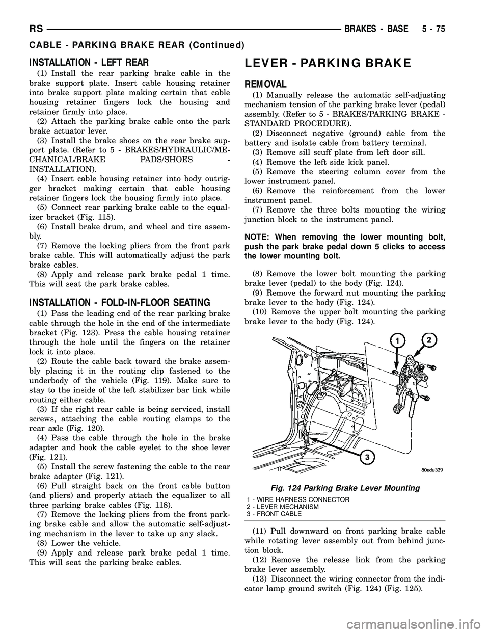
LEVER - PARKING BRAKE
REMOVAL
(1) Manually release the automatic self-adjusting
mechanism tension of the parking brake lever (pedal)
assembly. (Refer to 5 - BRAKES/PARKING BRAKE -
STANDARD PROCEDURE).
(2) Disconnect negative (ground) cable from the
battery and isolate cable from battery terminal.
(3) Remove sill scuff plate from left door sill.
(4) Remove the left side kick panel.
(5) Remove the steering column cover from the
lower instrument panel.
(6) Remove the reinforcement from the lower
instrument panel.
(7) Remove the three bolts mounting the wiring
junction block to the instrument panel.
NOTE: When removing the lower mounting bolt,
push the park brake pedal down 5 clicks to access
the lower mounting bolt.
(8) Remove the lower bolt mounting the parking
brake lever (pedal) to the body (Fig. 124).
(9) Remove the forward nut mounting the parking
brake lever to the body (Fig. 124).
(10) Remove the upper bolt mounting the parking
brake lever to the body (Fig. 124).
(11) Pull downward on front parking brake cable
while rotating lever assembly out from behind junc-
tion block.
(12) Remove the release link from the parking
brake lever assembly.
(13) Disconnect the wiring connector from the indi-
cator lamp ground switch (Fig. 124) (Fig. 125).
Fig. 124 Parking Brake Lever Mounting
1 - WIRE HARNESS CONNECTOR
2 - LEVER MECHANISM
3 - FRONT CABLE
RSBRAKES - BASE5-75
CABLE - PARKING BRAKE REAR (Continued)
Page 187 of 2339

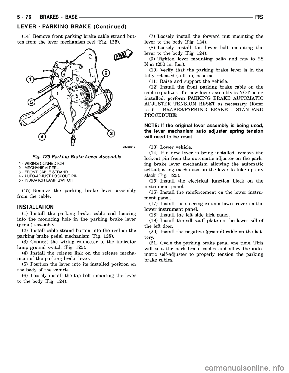
(14) Remove front parking brake cable strand but-
ton from the lever mechanism reel (Fig. 125).
(15) Remove the parking brake lever assembly
from the cable.
INSTALLATION
(1) Install the parking brake cable end housing
into the mounting hole in the parking brake lever
(pedal) assembly.
(2) Install cable strand button into the reel on the
parking brake pedal mechanism (Fig. 125).
(3) Connect the wiring connector to the indicator
lamp ground switch (Fig. 125).
(4) Install the release link on the release mecha-
nism of the parking brake lever.
(5) Position the lever into its installed position on
the body of the vehicle.
(6) Loosely install the top bolt mounting the lever
to the body (Fig. 124).(7) Loosely install the forward nut mounting the
lever to the body (Fig. 124).
(8) Loosely install the lower bolt mounting the
lever to the body (Fig. 124).
(9) Tighten lever mounting bolts and nut to 28
N´m (250 in. lbs.).
(10) Verify that the parking brake lever is in the
fully released (full up) position.
(11) Raise and support the vehicle.
(12) Install the front parking brake cable on the
cable equalizer. If a new lever assembly is NOT being
installed, perform PARKING BRAKE AUTOMATIC
ADJUSTER TENSION RESET as necessary. (Refer
to 5 - BRAKES/PARKING BRAKE - STANDARD
PROCEDURE)
NOTE: If the original lever assembly is being used,
the lever mechanism auto adjuster spring tension
will need to be reset.
(13) Lower vehicle.
(14) If a new lever is being installed, remove the
lockout pin from the automatic adjuster on the park-
ing brake lever mechanism allowing the automatic
self-adjusting mechanism in the lever to take up any
slack (Fig. 125).
(15) Install the electrical junction block on the
instrument panel.
(16) Install the reinforcement on the lower instru-
ment panel.
(17) Install the steering column lower cover on the
lower instrument panel.
(18) Install the left side kick panel.
(19) Install the sill scuff plate on the lower sill of
the left door.
(20) Install the negative (ground) cable on the bat-
tery.
(21) Cycle the parking brake pedal one time. This
will seat the park brake cables and allow the auto-
matic self-adjuster to properly tension the parking
brake cables.
Fig. 125 Parking Brake Lever Assembly
1 - WIRING CONNECTOR
2 - MECHANISM REEL
3 - FRONT CABLE STRAND
4 - AUTO-ADJUST LOCKOUT PIN
5 - INDICATOR LAMP SWITCH
5 - 76 BRAKES - BASERS
LEVER - PARKING BRAKE (Continued)
Page 188 of 2339

LEVER - PARKING BRAKE
(EXPORT)
REMOVAL - PARKING BRAKE LEVER AND
FRONT CABLE
(1) Raise vehicle. (Refer to LUBRICATION &
MAINTENANCE/HOISTING - STANDARD PROCE-
DURE)
(2) Grasp the exposed section of the front parking
brake cable and pull rearward on it. While holding
the park brake in this position, install a pair of lock-
ing pliers on the front parking brake cable just rear-
ward of the second body outrigger bracket (Fig. 126).
(3) Remove the left rear and intermediate parking
brake cables from the parking brake cable equalizer
(Fig. 127).
(4) Remove the equalizer from the front parking
brake cable.
(5) Remove the locking pliers from the front park-
ing brake cable. This will allow the adjuster in the
parking brake lever mechanism to rotate around to
its stop and remove the tension from the adjuster
and front park brake cable.
(6) Remove the front parking brake cable housing
from body outrigger bracket. Cable is removable by
sliding a 14 mm box wrench over the cable retainer
and compressing the three retaining fingers.Alter-
nate method:Use an aircraft type hose clamp and
screwdriver.
(7) Remove the four mounting nuts from the bot-
tom of the parking brake lever bracket.
(8) Lower vehicle.
(9) Remove the floor console. (Refer to 23 - BODY/
INTERIOR/FLOOR CONSOLE - REMOVAL)(10) If equipped with a manual transaxle, remove
the gearshift mechanism. (Refer to 21 - TRANSMIS-
SION/TRANSAXLE/MANUAL/SHIFT MECHANISM
- REMOVAL)
(11) Unhook the end of the parking brake cable
from the lever mechanism.
(12) Compress the parking brake cable retainer by
sliding a 14 mm wrench over the cable retainer and
compress the three (3) retaining fingers.
(13) Remove the three screws from the parking
brake grommet on the floor pan of the passenger
compartment.
(14) Lift the parking brake lever and slide the
parking brake cable out.
(15) Pull the cable through the floor pan from
inside the vehicle.
INSTALLATION - PARKING BRAKE LEVER AND
FRONT CABLE
(1) Pass the parking brake cable down through the
hole in the floor pan from inside of vehicle.
(2) Pass cable end button through the hole in the
lever bracket and press the cable housing into the
hole until all three retaining fingers lock the cable to
the lever bracket.
(3) Hook the end of the parking brake cable on the
parking brake lever mechanism.
(4) Press the cable grommet into the hole in the
floor pan and install the three screws securing it to
the floor pan.
(5) If equipped with a manual transaxle, install
the gearshift mechanism. (Refer to 21 - TRANSMIS-
SION/TRANSAXLE/MANUAL/SHIFT MECHANISM
- INSTALLATION)
Fig. 126 Locking Out Automatic Adjuster
1 - PARK BRAKE CABLE
2 - REAR BODY OUTRIGGER BRACKET
3 - LOCKING PLIERS
Fig. 127 Parking Brake Cable Equalizer
1 - EQUALIZER
2 - LEFT REAR PARKING BRAKE CABLE
3 - LOCKING NUT
4 - INTERMEDIATE PARKING BRAKE CABLE
5 - FRONT PARKING BRAKE CABLE
RSBRAKES - BASE5-77
Page 189 of 2339

(6) Install the floor console. (Refer to 23 - BODY/
INTERIOR/FLOOR CONSOLE - INSTALLATION)
(7) Raise the vehicle.
(8) Install the four mounting nuts securing the
parking brake lever bracket in place.
(9) Install the front park cable housing retainer to
the body outrigger bracket. Press the cable housing
into the outrigger hole until all three retaining fin-
gers lock the cable in place.
(10) Grasp the exposed section of the front parking
brake cable and pull rearward on it. While holding
the park brake in this position, install a pair of lock-
ing pliers on the front parking brake cable just rear-
ward of the second body outrigger bracket.
(11) Install the equalizer on the front parking
brake cable and install the left rear and intermediate
park brake cable in the correct location on the park-
ing brake cable equalizer (Fig. 127).
(12) Remove the locking pliers from the front park-
ing brake cable. This will allow the adjuster in the
park brake lever mechanism to tension the parking
brake cables.
(13) Lower the vehicle.
(14) Apply and release the parking brake lever one
time. This will seat the parking brake cables and
allow the auto adjuster in the parking brake lever
mechanism to correctly tension the parking brake
cables.
SHOES - PARKING BRAKE
REMOVAL
(1) AWD only - Set the parking brake.The park-
ing brake is set to keep the hub/bearing and
axle shaft from rotating when loosening the
hub nut.
(2) Raise vehicle. (Refer to LUBRICATION &
MAINTENANCE/HOISTING - STANDARD PROCE-
DURE).
(3) Remove the wheel and tire assembly.
(4) AWD only - Remove the cotter pin and nut
retainer (Fig. 128) from the stub shaft of the outer
C/V joint.
(5) AWD only - Remove the spring washer (Fig.
129) from the stub shaft of the outer C/V joint.
Fig. 128 Cotter Pin And Nut Retainer
1 - CALIPER
2 - COTTER PIN
3 - ROTOR
4 - NUT RETAINER
5 - OUTER C/V JOINT
Fig. 129 Spring Washer
1 - HUB NUT
2 - STUB SHAFT
3 - ROTOR
4 - SPRING WASHER
5 - 78 BRAKES - BASERS
LEVER - PARKING BRAKE (EXPORT) (Continued)
Page 190 of 2339

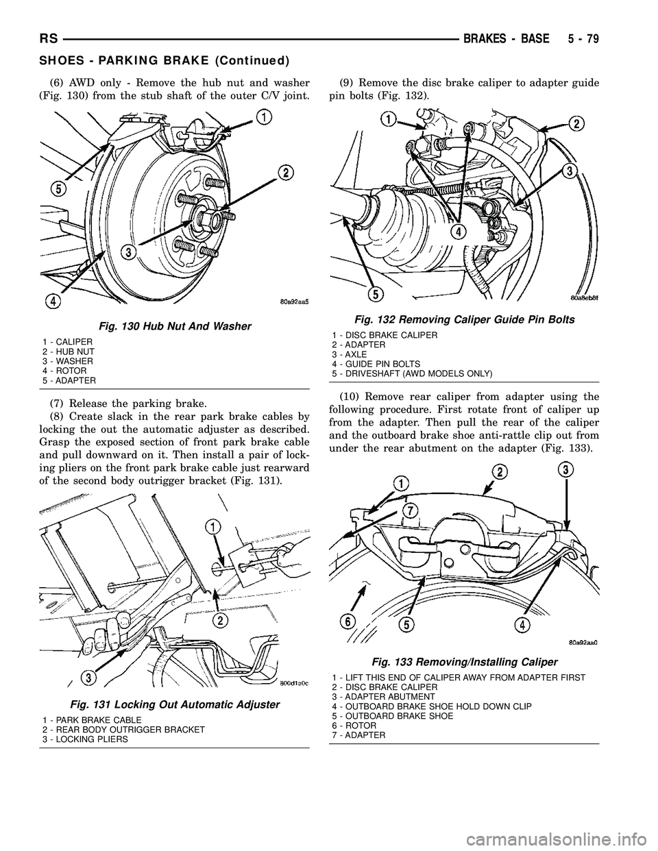
(6) AWD only - Remove the hub nut and washer
(Fig. 130) from the stub shaft of the outer C/V joint.
(7) Release the parking brake.
(8) Create slack in the rear park brake cables by
locking the out the automatic adjuster as described.
Grasp the exposed section of front park brake cable
and pull downward on it. Then install a pair of lock-
ing pliers on the front park brake cable just rearward
of the second body outrigger bracket (Fig. 131).(9) Remove the disc brake caliper to adapter guide
pin bolts (Fig. 132).
(10) Remove rear caliper from adapter using the
following procedure. First rotate front of caliper up
from the adapter. Then pull the rear of the caliper
and the outboard brake shoe anti-rattle clip out from
under the rear abutment on the adapter (Fig. 133).
Fig. 130 Hub Nut And Washer
1 - CALIPER
2 - HUB NUT
3 - WASHER
4 - ROTOR
5 - ADAPTER
Fig. 131 Locking Out Automatic Adjuster
1 - PARK BRAKE CABLE
2 - REAR BODY OUTRIGGER BRACKET
3 - LOCKING PLIERS
Fig. 132 Removing Caliper Guide Pin Bolts
1 - DISC BRAKE CALIPER
2 - ADAPTER
3 - AXLE
4 - GUIDE PIN BOLTS
5 - DRIVESHAFT (AWD MODELS ONLY)
Fig. 133 Removing/Installing Caliper
1 - LIFT THIS END OF CALIPER AWAY FROM ADAPTER FIRST
2 - DISC BRAKE CALIPER
3 - ADAPTER ABUTMENT
4 - OUTBOARD BRAKE SHOE HOLD DOWN CLIP
5 - OUTBOARD BRAKE SHOE
6 - ROTOR
7 - ADAPTER
RSBRAKES - BASE5-79
SHOES - PARKING BRAKE (Continued)