Rear control CHRYSLER VOYAGER 2005 User Guide
[x] Cancel search | Manufacturer: CHRYSLER, Model Year: 2005, Model line: VOYAGER, Model: CHRYSLER VOYAGER 2005Pages: 2339, PDF Size: 59.69 MB
Page 57 of 2339
(3) Install the reinforcement on the front suspen-
sion cradle crossmember and install the bolts attach-
ing the reinforcement to the cradle crossmember
(Fig. 22). Tighten the M-14 size bolts to a torque of
153 N´m (113 ft. lbs.). Tighten the M-12 size bolts to
a torque of 106 N´m (78 ft. lbs.).
(4) Install the lower control arm rear bushing
retainer bolts through reinforcement on each side of
each lower control arm rear bushing. Tighten these
M-10 size bolts to a torque of 61 N´m (45 ft. lbs.).
(5) Install the two bolts and bushings attaching
the reinforcement and rear of cradle crossmember to
body of vehicle (Fig. 22). Tighten bolts to a torque of
163 N´m (120 ft. lbs.).
(6) Install the power steering cooler (Fig. 21).
Tighten bolts to a torque of 11 N´m (100 in. lbs.).
(7) Reinstall steering knuckle, brake rotor and cal-
iper. (Refer to 2 - SUSPENSION/FRONT/KNUCKLE
- INSTALLATION)
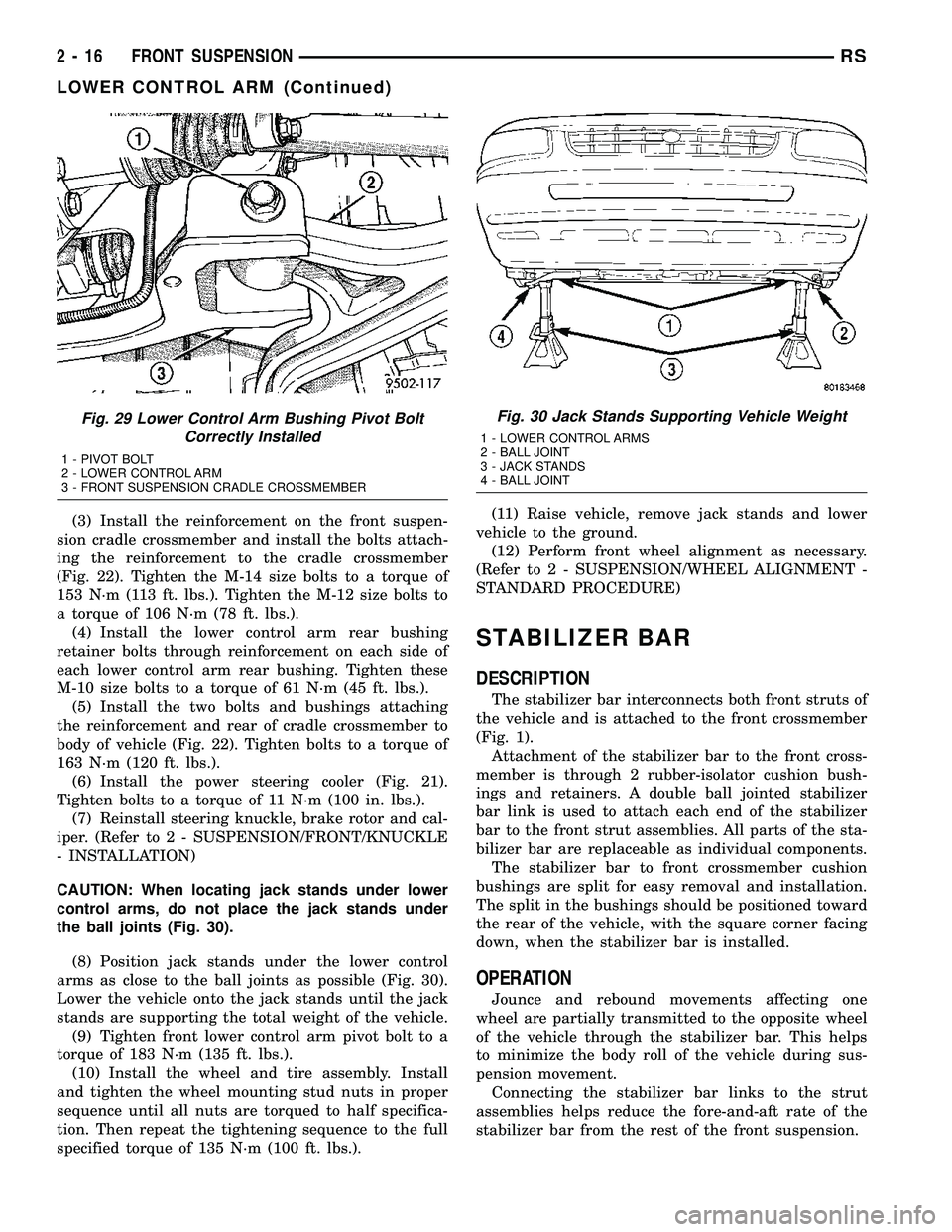
CAUTION: When locating jack stands under lower
control arms, do not place the jack stands under
the ball joints (Fig. 30).
(8) Position jack stands under the lower control
arms as close to the ball joints as possible (Fig. 30).
Lower the vehicle onto the jack stands until the jack
stands are supporting the total weight of the vehicle.
(9) Tighten front lower control arm pivot bolt to a
torque of 183 N´m (135 ft. lbs.).
(10) Install the wheel and tire assembly. Install
and tighten the wheel mounting stud nuts in proper
sequence until all nuts are torqued to half specifica-
tion. Then repeat the tightening sequence to the full
specified torque of 135 N´m (100 ft. lbs.).(11) Raise vehicle, remove jack stands and lower
vehicle to the ground.
(12) Perform front wheel alignment as necessary.
(Refer to 2 - SUSPENSION/WHEEL ALIGNMENT -
STANDARD PROCEDURE)
STABILIZER BAR
DESCRIPTION
The stabilizer bar interconnects both front struts of
the vehicle and is attached to the front crossmember
(Fig. 1).
Attachment of the stabilizer bar to the front cross-
member is through 2 rubber-isolator cushion bush-
ings and retainers. A double ball jointed stabilizer
bar link is used to attach each end of the stabilizer
bar to the front strut assemblies. All parts of the sta-
bilizer bar are replaceable as individual components.
The stabilizer bar to front crossmember cushion
bushings are split for easy removal and installation.
The split in the bushings should be positioned toward
the rear of the vehicle, with the square corner facing
down, when the stabilizer bar is installed.
OPERATION
Jounce and rebound movements affecting one
wheel are partially transmitted to the opposite wheel
of the vehicle through the stabilizer bar. This helps
to minimize the body roll of the vehicle during sus-
pension movement.
Connecting the stabilizer bar links to the strut
assemblies helps reduce the fore-and-aft rate of the
stabilizer bar from the rest of the front suspension.
Fig. 29 Lower Control Arm Bushing Pivot Bolt
Correctly Installed
1 - PIVOT BOLT
2 - LOWER CONTROL ARM
3 - FRONT SUSPENSION CRADLE CROSSMEMBER
Fig. 30 Jack Stands Supporting Vehicle Weight
1 - LOWER CONTROL ARMS
2 - BALL JOINT
3 - JACK STANDS
4 - BALL JOINT
2 - 16 FRONT SUSPENSIONRS
LOWER CONTROL ARM (Continued)
Page 58 of 2339

REMOVAL
(1) Raise vehicle. (Refer to LUBRICATION &
MAINTENANCE/HOISTING - STANDARD PROCE-
DURE)
(2) Remove the bolts fastening the power steering
cooler to the front suspension cradle crossmember
reinforcement (Fig. 31).
(3) Remove the lower control arm rear bushing
retainer bolts located on each side of each lower con-
trol arm rear bushing.
NOTE: The bolts fastening the cradle crossmember
reinforcement are of two different thread sizes. Note
the location of the various sizes.
(4) Remove the bolts attaching the cradle cross-
member reinforcement to the front suspension cradle
crossmember (Fig. 32). Remove the 2 bolts fastening
the reinforcement and rear of cradle crossmember to
the body of the vehicle. Remove the reinforcement.
CAUTION: When removing the nut from the stud of
the stabilizer bar link, do not allow the stud to
rotate in it's socket. Hold the stud from rotating by
placing an open-end wrench on the flat machined
into the stud (Fig. 33).
(5) Remove the stabilizer bar links from each end
of the stabilizer bar (Fig. 33). To do so, place an open-
end wrench on the flat machined into the link's
mounting stud, then remove the nut while holding
the wrench in place. Push each stud out of the hole
in the stabilizer bar.(6) Remove the stabilizer bar bushing (cushion)
retainers from the front suspension cradle crossmem-
ber (Fig. 34).
(7) Remove the stabilizer bar and bushings (cush-
ions) as an assembly from the front suspension cra-
dle crossmember.
INSPECTION
Inspect for broken or distorted stabilizer bar bush-
ings (cushions), bushing retainers, and worn or dam-
aged stabilizer bar links.
INSTALLATION
NOTE: Two different diameter stabilizer bars are
available for this vehicle. Therefore, two different
size bushings/cushions are also used. Use the cor-
rect bushing/cushion on the correct stabilizer bar.
Fig. 31 Power Steering Cooler
1 - CRADLE CROSSMEMBER REINFORCEMENT
2 - POWER STEERING COOLERFig. 32 Cradle Crossmember Reinforcement
Attachment
1 - STEERING GEAR
2 - RIGHT LOWER CONTROL ARM
3 - LEFT LOWER CONTROL ARM
4 - CRADLE CROSSMEMBER REINFORCEMENT
5 - REAR CRADLE CROSSMEMBER ISOLATOR BUSHING
6 - STABILIZER BAR
7 - CRADLE CROSSMEMBER
RSFRONT SUSPENSION2-17
STABILIZER BAR (Continued)
Page 60 of 2339
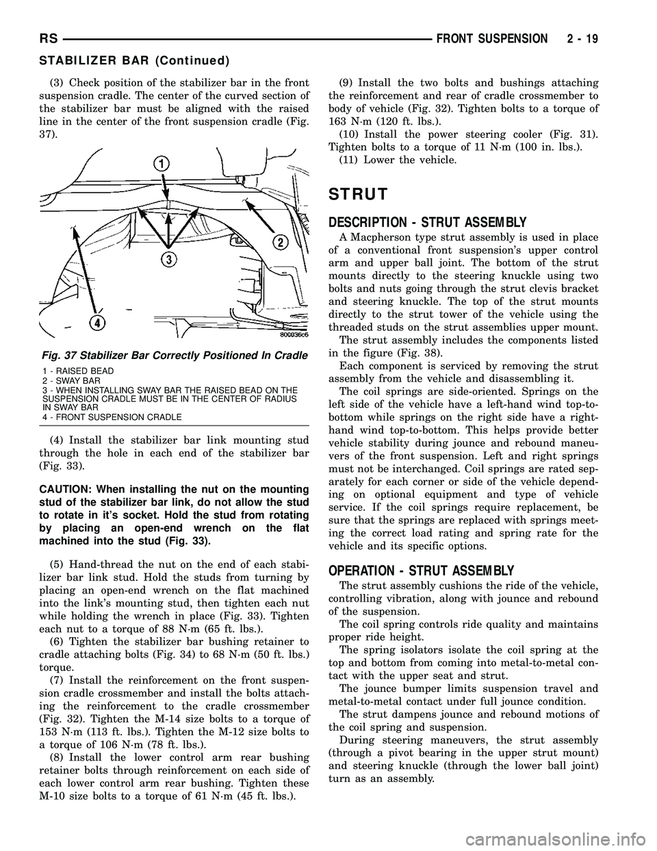
(3) Check position of the stabilizer bar in the front
suspension cradle. The center of the curved section of
the stabilizer bar must be aligned with the raised
line in the center of the front suspension cradle (Fig.
37).
(4) Install the stabilizer bar link mounting stud
through the hole in each end of the stabilizer bar
(Fig. 33).
CAUTION: When installing the nut on the mounting
stud of the stabilizer bar link, do not allow the stud
to rotate in it's socket. Hold the stud from rotating
by placing an open-end wrench on the flat
machined into the stud (Fig. 33).
(5) Hand-thread the nut on the end of each stabi-
lizer bar link stud. Hold the studs from turning by
placing an open-end wrench on the flat machined
into the link's mounting stud, then tighten each nut
while holding the wrench in place (Fig. 33). Tighten
each nut to a torque of 88 N´m (65 ft. lbs.).
(6) Tighten the stabilizer bar bushing retainer to
cradle attaching bolts (Fig. 34) to 68 N´m (50 ft. lbs.)
torque.
(7) Install the reinforcement on the front suspen-
sion cradle crossmember and install the bolts attach-
ing the reinforcement to the cradle crossmember
(Fig. 32). Tighten the M-14 size bolts to a torque of
153 N´m (113 ft. lbs.). Tighten the M-12 size bolts to
a torque of 106 N´m (78 ft. lbs.).
(8) Install the lower control arm rear bushing
retainer bolts through reinforcement on each side of
each lower control arm rear bushing. Tighten these
M-10 size bolts to a torque of 61 N´m (45 ft. lbs.).(9) Install the two bolts and bushings attaching
the reinforcement and rear of cradle crossmember to
body of vehicle (Fig. 32). Tighten bolts to a torque of
163 N´m (120 ft. lbs.).
(10) Install the power steering cooler (Fig. 31).
Tighten bolts to a torque of 11 N´m (100 in. lbs.).
(11) Lower the vehicle.
STRUT
DESCRIPTION - STRUT ASSEMBLY
A Macpherson type strut assembly is used in place
of a conventional front suspension's upper control
arm and upper ball joint. The bottom of the strut
mounts directly to the steering knuckle using two
bolts and nuts going through the strut clevis bracket
and steering knuckle. The top of the strut mounts
directly to the strut tower of the vehicle using the
threaded studs on the strut assemblies upper mount.
The strut assembly includes the components listed
in the figure (Fig. 38).
Each component is serviced by removing the strut
assembly from the vehicle and disassembling it.
The coil springs are side-oriented. Springs on the
left side of the vehicle have a left-hand wind top-to-
bottom while springs on the right side have a right-
hand wind top-to-bottom. This helps provide better
vehicle stability during jounce and rebound maneu-
vers of the front suspension. Left and right springs
must not be interchanged. Coil springs are rated sep-
arately for each corner or side of the vehicle depend-
ing on optional equipment and type of vehicle
service. If the coil springs require replacement, be
sure that the springs are replaced with springs meet-
ing the correct load rating and spring rate for the
vehicle and its specific options.
OPERATION - STRUT ASSEMBLY
The strut assembly cushions the ride of the vehicle,
controlling vibration, along with jounce and rebound
of the suspension.
The coil spring controls ride quality and maintains
proper ride height.
The spring isolators isolate the coil spring at the
top and bottom from coming into metal-to-metal con-
tact with the upper seat and strut.
The jounce bumper limits suspension travel and
metal-to-metal contact under full jounce condition.
The strut dampens jounce and rebound motions of
the coil spring and suspension.
During steering maneuvers, the strut assembly
(through a pivot bearing in the upper strut mount)
and steering knuckle (through the lower ball joint)
turn as an assembly.
Fig. 37 Stabilizer Bar Correctly Positioned In Cradle
1 - RAISED BEAD
2-SWAYBAR
3 - WHEN INSTALLING SWAY BAR THE RAISED BEAD ON THE
SUSPENSION CRADLE MUST BE IN THE CENTER OF RADIUS
IN SWAY BAR
4 - FRONT SUSPENSION CRADLE
RSFRONT SUSPENSION2-19
STABILIZER BAR (Continued)
Page 87 of 2339
body of the vehicle by an isolator bushing located in
each end of the track bar.
OPERATION
The track bar prevents excessive side-to-side move-
ment of the rear axle. The track bar is used to keep
the location of the axle in the correct position for
optimum handling and control of the vehicle.
REMOVAL
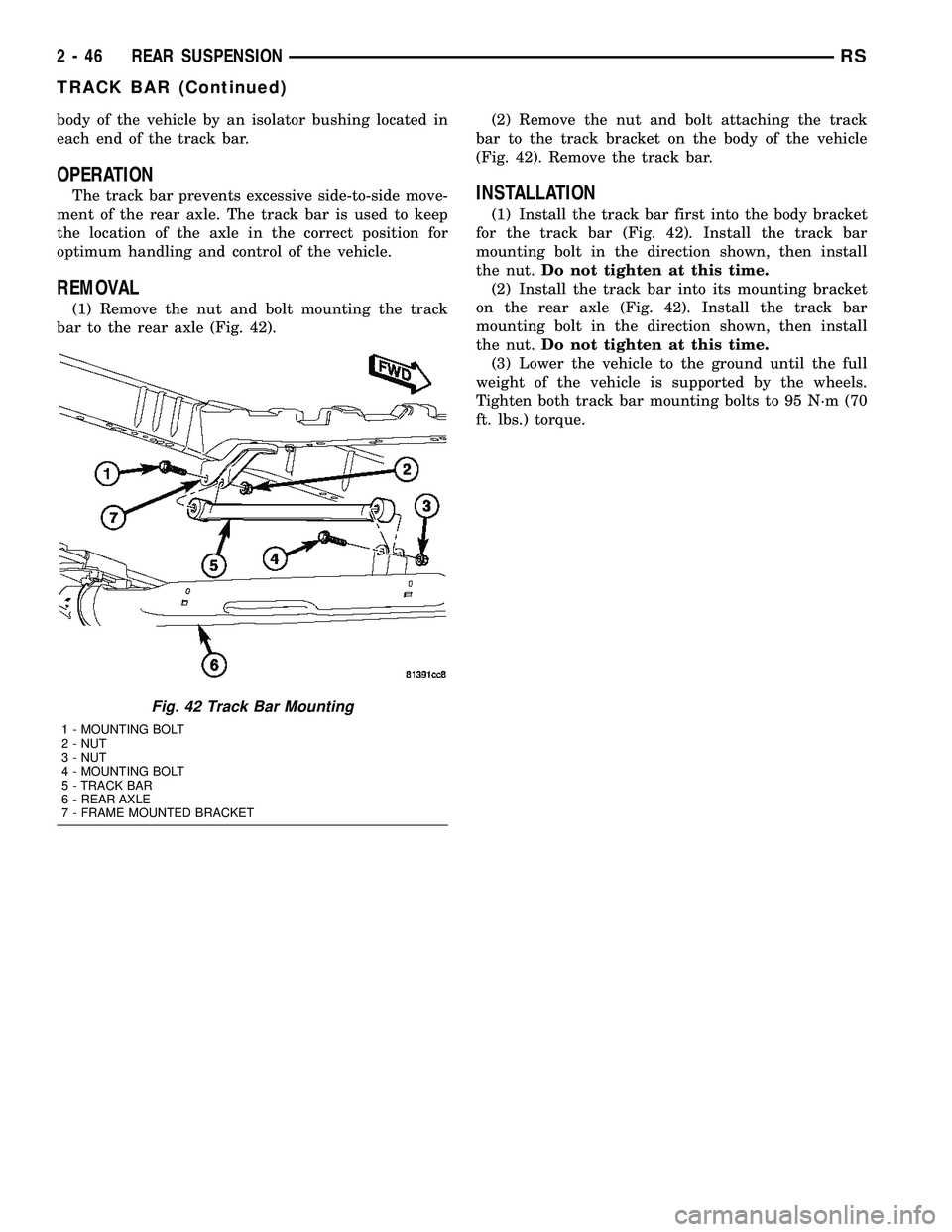
(1) Remove the nut and bolt mounting the track
bar to the rear axle (Fig. 42).(2) Remove the nut and bolt attaching the track
bar to the track bracket on the body of the vehicle
(Fig. 42). Remove the track bar.
INSTALLATION
(1) Install the track bar first into the body bracket
for the track bar (Fig. 42). Install the track bar
mounting bolt in the direction shown, then install
the nut.Do not tighten at this time.
(2) Install the track bar into its mounting bracket
on the rear axle (Fig. 42). Install the track bar
mounting bolt in the direction shown, then install
the nut.Do not tighten at this time.
(3) Lower the vehicle to the ground until the full
weight of the vehicle is supported by the wheels.
Tighten both track bar mounting bolts to 95 N´m (70
ft. lbs.) torque.
Fig. 42 Track Bar Mounting
1 - MOUNTING BOLT
2 - NUT
3 - NUT
4 - MOUNTING BOLT
5 - TRACK BAR
6 - REAR AXLE
7 - FRAME MOUNTED BRACKET
2 - 46 REAR SUSPENSIONRS
TRACK BAR (Continued)
Page 90 of 2339

TOE-OUT ON TURNS
Toe-out on turns is the relative positioning of the
front wheels while steering through a turn (Fig. 4).
This compensates for each front wheel's turning
radius. As the vehicle encounters a turn, the out-
board wheel must travel in a larger radius circle
than the inboard wheel. The steering system is
designed to make each wheel follow its particular
radius circle. To accomplish this, the front wheels
must progressively toe outward as the steering is
turned from center. This eliminates tire scrubbing
and undue tire wear when steering a vehicle through
a turn.
DYNAMIC TOE PATTERN
Dynamic toe pattern is the inward and outward toe
movement of the front and rear tires through the
suspension's jounce and rebound travel. As the vehi-
cle's suspension moves up and down, the toe pattern
varies. Toe pattern is critical in controlling the direc-
tional stability of the vehicle while in motion. Front
and rear dynamic toe pattern is preset by the factory
at the time the vehicle is assembled.
It is not necessary to check or adjust front or rear
dynamic toe pattern when doing a normal wheel
alignment. The only time dynamic toe pattern needs
to be checked or adjusted is if the frame of the vehi-
cle has been damaged.
STEERING AXIS INCLINATION (S. A. I.)
Steering axis inclination is the angle between a
true vertical line starting at the center of the tire at
the road contact point and a line drawn through the
center of the upper ball joint (or strut) and the lower
ball joint (Fig. 5). S.A.I. is built into the vehicle and
is not an adjustable angle. If S.A.I. is not within
specifications, a bent or damaged suspension compo-
nent may be the cause.
INCLUDED ANGLE (I. A.)
Included angle is the sum of the S.A.I. angle plus
or minus the camber angle, depending on whether or
not the wheel has positive or negative camber (Fig.
5). If camber is positive, add the camber angle to the
S.A.I. angle. If camber is negative, subtract the cam-
ber angle from the S.A.I. angle. Included angle is not
adjustable, but can be used to diagnose a frame mis-
alignment or bent suspension component (spindle,
strut).
Fig. 4 Toe-Out On Turns
1 - TOE-OUT ON TURNS
Fig. 5 S.A.I. and I.A.
1 - S.A.I.
2 - CAMBER
3 - I.A.
RSWHEEL ALIGNMENT2-49
WHEEL ALIGNMENT (Continued)
Page 92 of 2339
CONDITION POSSIBLE CAUSES CORRECTION
Front End Clunk Or Snap
On Turns1. Loose lug nuts 1. Verify wheel lug nut torque
2. Worn or broken C/V joint 2. Replace C/V joint
3. Worn or loose tie rod 3. Tighten or replace tie rod end
4. Worn or loose ball joint 4. Tighten or replace ball joint
5. Worn/loose control arm bushing 5. Replace control arm bushing
6. Loose stabilizer bar. 6. Tighten stabilizer bar to specified
torque
7. Loose strut mount to body
attachment7. Tighten strut attachment to specified
torque
8. Loose crossmember bolts 8. Tighten crossmember bolts to
specified torque
Front End Whine With
Vehicle Going Straight At A
Constant Speed1. Defective wheel bearing 1. Replace wheel bearing
2. Incorrect wheel alignment 2. Check and reset wheel alignment
3. Worn tires 3. Replace tires
4. Worn or defective transaxle gears or
bearings4. Replace transaxle gears or bearings
Front End Growl Or
Grinding With Vehicle
Going Straight At A
Constant Speed1. Engine mount grounding 1. Reposition engine as required
2. Worn or broken C/V joint 2. Replace C/V joint
Front End Whine When
Accelerating Or
Decelerating1. Worn or defective transaxle gears or
bearings1. Replace transaxle gears or bearings
Front End Clunk When
Accelerating Or
Decelerating1. Worn or broken engine mount 1. Replace engine mount
2. Worn or defective transaxle gears or
bearings2. Replace transaxle gears or bearings
3. Loose lug nuts 3. Verify wheel lug nut torque
4. Worn or broken C/V joint 4. Replace C/V joint
5. Worn or loose ball joint 5. Tighten or replace ball joint
6. Worn or loose control arm bushing 6. Replace control arm bushing
7. Loose crossmember bolts 7. Tighten crossmember bolts to
specified torque
8. Worn tie rod end 8. Replace tie rod end
Road Wander 1. Incorrect tire pressure 1. Inflate tires to recommended pressure
2. Incorrect front or rear wheel toe 2. Check and reset wheel toe
3. Worn wheel bearings 3. Replace wheel bearing
4. Worn control arm bushings 4. Replace control arm bushing
5. Excessive friction in steering gear 5. Replace steering gear
6. Excessive friction in steering shaft
coupling6. Replace steering coupler
7. Excessive friction in strut upper
bearing7. Replace strut bearing
RSWHEEL ALIGNMENT2-51
WHEEL ALIGNMENT (Continued)
Page 114 of 2339
STANDARD PROCEDURE
STANDARD PROCEDURE - PARKING
BRAKE AUTOMATIC ADJUSTER TENSION
RELEASE...........................63
STANDARD PROCEDURE - PARKING
BRAKE AUTOMATIC ADJUSTER TENSION
RESET.............................64
STANDARD PROCEDURE - CABLE END
CLEANING AND LUBRICATION...........65
ADJUSTMENTS
ADJUSTMENT - PARKING BRAKE
CABLES............................65
CABLE - PARKING BRAKE FRONT
REMOVAL
REMOVAL...........................66
REMOVAL - FOLD-IN-FLOOR SEATING.....66
REMOVAL - EXPORT..................67
INSTALLATION
INSTALLATION.......................67
INSTALLATION - FOLD-IN-FLOOR SEATING . 68
INSTALLATION - EXPORT...............68
CABLE - PARKING BRAKE INTERMEDIATE
REMOVAL.............................69
INSTALLATION.........................69CABLE - PARKING BRAKE REAR
REMOVAL
REMOVAL - RIGHT REAR...............70
REMOVAL - LEFT REAR................71
REMOVAL - FOLD-IN-FLOOR SEATING.....72
INSTALLATION
INSTALLATION - RIGHT REAR...........74
INSTALLATION - LEFT REAR............75
INSTALLATION - FOLD-IN-FLOOR
SEATING............................75
LEVER - PARKING BRAKE
REMOVAL.............................75
INSTALLATION.........................76
LEVER - PARKING BRAKE (EXPORT)
REMOVAL - PARKING BRAKE LEVER AND
FRONT CABLE.......................77
INSTALLATION - PARKING BRAKE LEVER
AND FRONT CABLE...................77
SHOES - PARKING BRAKE
REMOVAL.............................78
INSTALLATION.........................84
ADJUSTMENTS
ADJUSTMENT - PARKING BRAKE SHOES . . 85
BRAKES - BASE
DESCRIPTION
DESCRIPTION - BASE BRAKES
The base brake system consists of the following
components:
²Brake pedal
²Power brake booster
²Master cylinder
²Brake tubes and hoses
²Proportioning valve (non-ABS vehicles only)
²Disc brakes
²Drum brakes
²Brake lamp switch
²Brake fluid level switch
²Parking brakes
Front disc brakes control the braking of the front
wheels; rear braking is controlled by rear drum
brakes or rear disc brakes depending on options.
The hydraulic brake system is diagonally split on
both the non-antilock braking systems and antilock
braking systems. That means the left front and right
rear brakes are on one hydraulic circuit and the right
front and left rear are on the other.
For information on the brake lamp switch, (Refer
to 8 - ELECTRICAL/LAMPS/LIGHTING - EXTERI-
OR/BRAKE LAMP SWITCH - DESCRIPTION)Vehicles equipped with the optional antilock brake
system (ABS) use a system designated Mark 20e. It
is available with or without traction control. This
system shares most base brake hardware used on
vehicles without ABS. ABS components are described
in detail in ANTILOCK BRAKE SYSTEM.DESCRIPTION - BASE BRAKES (EXPORT)
Four-Wheel Disc Antilock Brakes are standard on
all models.
OPERATION - BASE BRAKES
When a vehicle needs to be stopped, the driver
applies the brake pedal. The brake pedal pushes the
input rod of the power brake booster into the booster.
The booster uses vacuum to ease pedal effort as force
is transferred through the booster to the master cyl-
inder. The booster's output rod pushes in the master
cylinder's primary and secondary pistons applying
hydraulic pressure through the chassis brake tubes
to the brakes at each tire and wheel assembly.
The parking brakes are foot-operated. When
applied, the parking brake lever pulls on cables that
actuate brake shoes at each rear wheel. These shoes
come in contact with a hub mounted drum (drum for
disc/drum brakes or drum-in-hat for disc/disc brakes)
and hold it in place.
RSBRAKES - BASE5-3
Page 123 of 2339
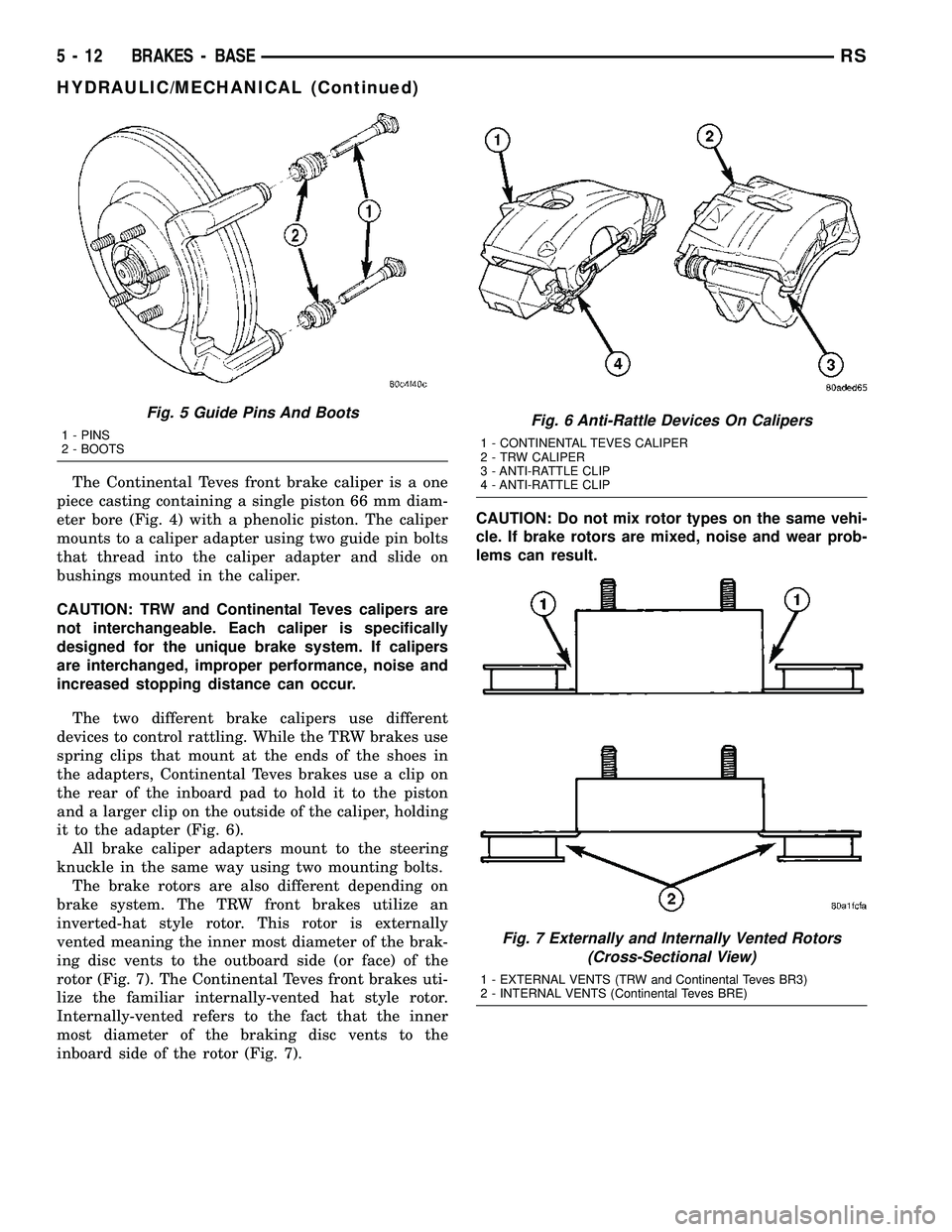
The Continental Teves front brake caliper is a one
piece casting containing a single piston 66 mm diam-
eter bore (Fig. 4) with a phenolic piston. The caliper
mounts to a caliper adapter using two guide pin bolts
that thread into the caliper adapter and slide on
bushings mounted in the caliper.
CAUTION: TRW and Continental Teves calipers are
not interchangeable. Each caliper is specifically
designed for the unique brake system. If calipers
are interchanged, improper performance, noise and
increased stopping distance can occur.
The two different brake calipers use different
devices to control rattling. While the TRW brakes use
spring clips that mount at the ends of the shoes in
the adapters, Continental Teves brakes use a clip on
the rear of the inboard pad to hold it to the piston
and a larger clip on the outside of the caliper, holding
it to the adapter (Fig. 6).
All brake caliper adapters mount to the steering
knuckle in the same way using two mounting bolts.
The brake rotors are also different depending on
brake system. The TRW front brakes utilize an
inverted-hat style rotor. This rotor is externally
vented meaning the inner most diameter of the brak-
ing disc vents to the outboard side (or face) of the
rotor (Fig. 7). The Continental Teves front brakes uti-
lize the familiar internally-vented hat style rotor.
Internally-vented refers to the fact that the inner
most diameter of the braking disc vents to the
inboard side of the rotor (Fig. 7).CAUTION: Do not mix rotor types on the same vehi-
cle. If brake rotors are mixed, noise and wear prob-
lems can result.
Fig. 5 Guide Pins And Boots
1 - PINS
2 - BOOTSFig. 6 Anti-Rattle Devices On Calipers
1 - CONTINENTAL TEVES CALIPER
2 - TRW CALIPER
3 - ANTI-RATTLE CLIP
4 - ANTI-RATTLE CLIP
Fig. 7 Externally and Internally Vented Rotors
(Cross-Sectional View)
1 - EXTERNAL VENTS (TRW and Continental Teves BR3)
2 - INTERNAL VENTS (Continental Teves BRE)
5 - 12 BRAKES - BASERS
HYDRAULIC/MECHANICAL (Continued)
Page 125 of 2339
As disc brake shoe linings wear, master cylinder
reservoir brake fluid level will drop. Adjust as neces-
sary. Fluid level should always be checked after
replacing shoes.
OPERATION - DISC BRAKES (REAR)
The rear disc brakes operate similarly to front disc
brakes, however, there are some features that require
different service procedures.
DIAGNOSIS AND TESTING - DRUM BRAKE
AUTOMATIC ADJUSTER
The rear drum brakes on this vehicle automatically
adjust when required during the normal operation of
the vehicle every time the brakes are applied. Use
the following procedure to test the operation of the
automatic adjuster.
Place the vehicle on a hoist with a helper in the
driver's seat to apply the brakes. Remove the access
plug from the adjustment hole in each brake support
plate to provide visual access of the brake adjuster
star wheel.
To eliminate the condition where maximum adjust-
ment of the rear brake shoes does not allow the auto-
matic adjuster to operate when tested, back the star
wheel off approximately 30 notches. It will be neces-
sary to hold the adjuster lever away from the star
wheel to permit this adjustment.
Have the helper apply the brakes. Upon applica-
tion of the brake pedal, the adjuster lever should
move down, turning the adjuster star wheel. Thus, a
definite rotation of the adjuster star wheel can be
observed if the automatic adjuster is working prop-
erly. If one or more adjusters do not function prop-
erly, the respective drum must be removed for
adjuster servicing.
BRAKE LINES
DESCRIPTION - BRAKE TUBES AND HOSES
The brake tubes are steel with a corrosion-resis-
tant nylon coating applied to the external surfaces.
The flex hoses are made of reinforced rubber with fit-
tings at each end.
The primary and secondary brake tubes leading
from the master cylinder to the ABS ICU Hydraulic
Control Unit (HCU) or the non-ABS junction block
have a special flexible section. This flexible section is
required due to cradle movement while the vehicle is
in motion (The ICU and non-ABS junction block are
mounted to the cradle).If replacement of these
lines is necessary, only the original factory
brake line containing the flexible section must
be used.
OPERATION - BRAKE TUBES AND HOSES
The purpose of the chassis brake tubes and flex
hoses is to transfer the pressurized brake fluid devel-
oped by the master cylinder to the wheel brakes of
the vehicle. The flex hoses are made of rubber to
allow for the movement of the vehicle's suspension.
INSPECTION - BRAKE TUBES AND HOSES
Flexible rubber hose is used at both front brakes
and at the rear axle. Inspection of brake hoses
should be performed whenever the brake system is
serviced and every 7,500 miles or 12 months, which-
ever comes first (every engine oil change). Inspect
hydraulic brake hoses for surface cracking, scuffing,
or worn spots. If the fabric casing of the rubber hose
becomes exposed due to cracks or abrasions in the
rubber hose cover, the hose should be replaced imme-
diately. Eventual deterioration of the hose can take
place with possible burst failure. Faulty installation
can cause twisting, resulting in wheel, tire, or chassis
interference.
The brake tubing should be inspected periodically
for evidence of physical damage or contact with mov-
ing or hot components.
The flexible brake tube sections used on this vehi-
cle in the primary and secondary tubes from the
master cylinder to the ABS hydraulic control unit
connections must also be inspected. This flexible tub-
ing must be inspected for kinks, fraying and contact
with other components or with the body of the vehi-
cle.
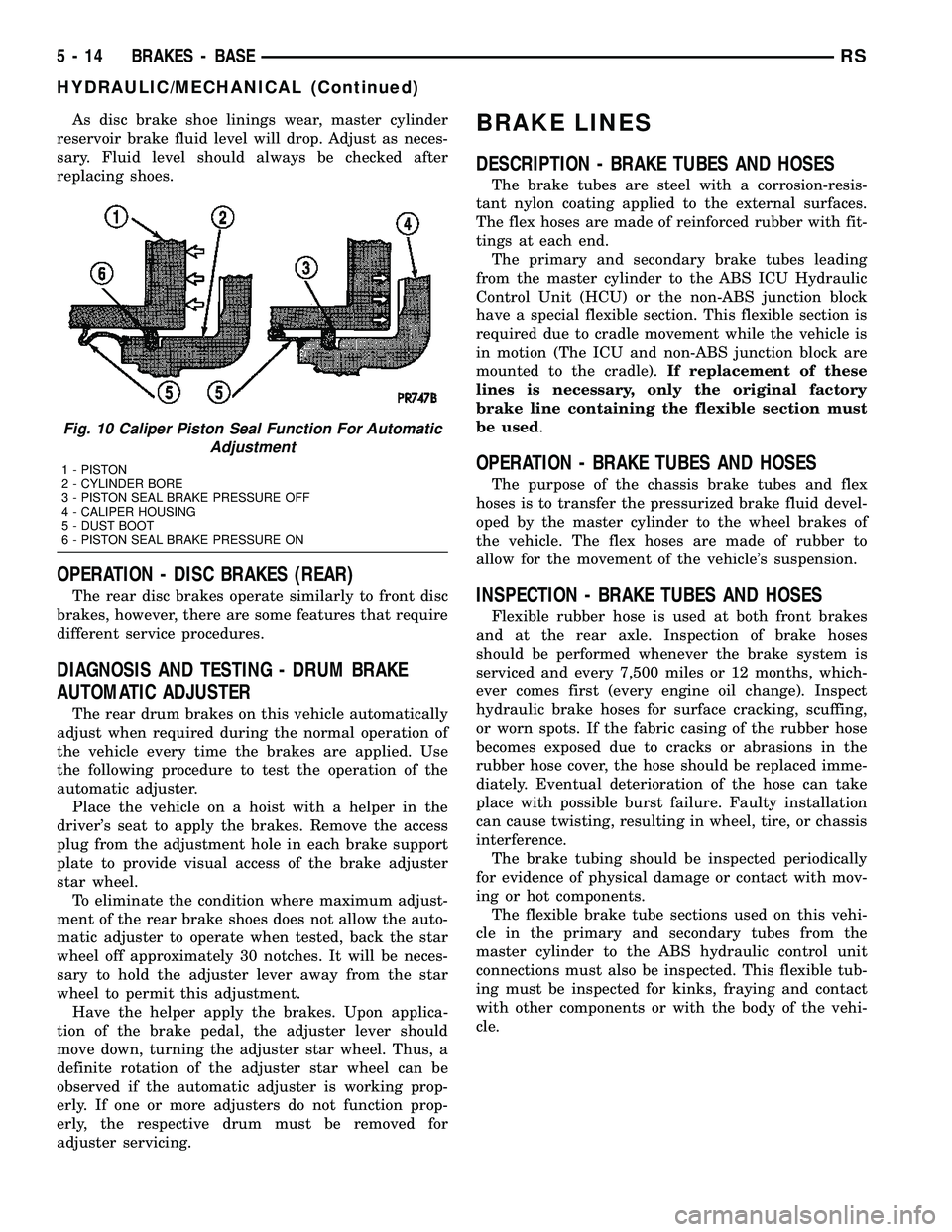
Fig. 10 Caliper Piston Seal Function For Automatic
Adjustment
1 - PISTON
2 - CYLINDER BORE
3 - PISTON SEAL BRAKE PRESSURE OFF
4 - CALIPER HOUSING
5 - DUST BOOT
6 - PISTON SEAL BRAKE PRESSURE ON
5 - 14 BRAKES - BASERS
HYDRAULIC/MECHANICAL (Continued)
Page 147 of 2339
OPERATION
When the brake pedal is depressed, the master cyl-
inder primary and secondary pistons apply brake
pressure through the chassis tubes to the brakes at
each tire and wheel assembly.
The master cylinder primary outlet port supplies
hydraulic pressure to the right front and left rear
brakes. The secondary outlet port supplies hydraulic
pressure to the left front and right rear brakes.
STANDARD PROCEDURE - MASTER CYLINDER
BLEEDING
CAUTION: When clamping master cylinder in vise,
only clamp master cylinder by its mounting flange.
Do not clamp master cylinder piston rod, reservoir,
seal or body.
(1) Clamp master cylinder in a vise.
NOTE: Use correct bleeder tubes when bleeding
master cylinder. Master cylinder outlet ports vary in
size and type depending on whether master cylin-
der is for a vehicle equipped with ABS or not. ABS
equipped master cylinders require the additional
use of ISO style flare adapters supplied in Special
Tool Package 8822 to be used in conjunction with
Bleeder Tubes, Special Tool Package 8358.
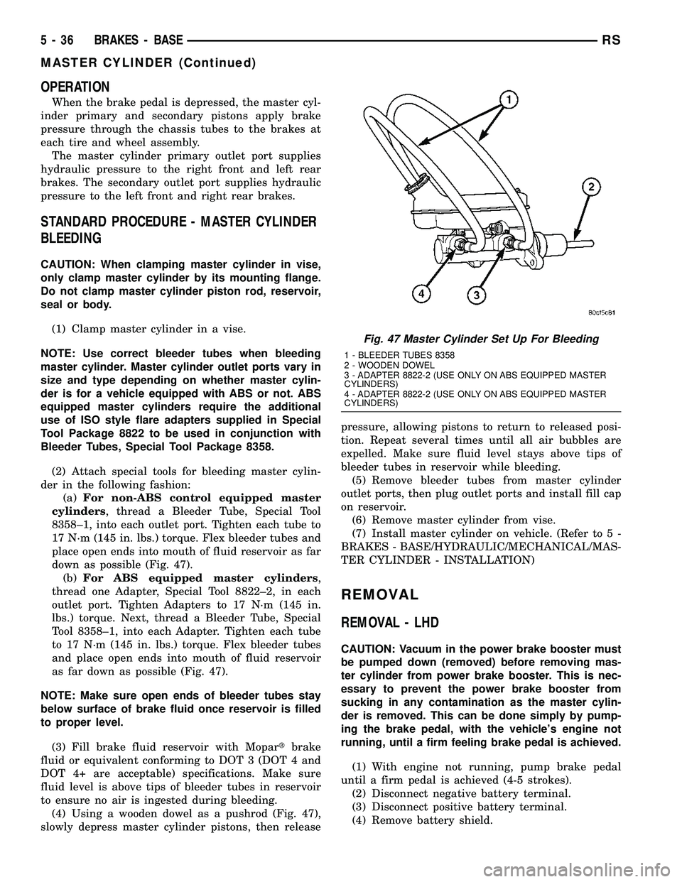
(2) Attach special tools for bleeding master cylin-
der in the following fashion:
(a)For non-ABS control equipped master
cylinders, thread a Bleeder Tube, Special Tool
8358±1, into each outlet port. Tighten each tube to
17 N´m (145 in. lbs.) torque. Flex bleeder tubes and
place open ends into mouth of fluid reservoir as far
down as possible (Fig. 47).
(b)For ABS equipped master cylinders,
thread one Adapter, Special Tool 8822±2, in each
outlet port. Tighten Adapters to 17 N´m (145 in.
lbs.) torque. Next, thread a Bleeder Tube, Special
Tool 8358±1, into each Adapter. Tighten each tube
to 17 N´m (145 in. lbs.) torque. Flex bleeder tubes
and place open ends into mouth of fluid reservoir
as far down as possible (Fig. 47).
NOTE: Make sure open ends of bleeder tubes stay
below surface of brake fluid once reservoir is filled
to proper level.
(3) Fill brake fluid reservoir with Mopartbrake
fluid or equivalent conforming to DOT 3 (DOT 4 and
DOT 4+ are acceptable) specifications. Make sure
fluid level is above tips of bleeder tubes in reservoir
to ensure no air is ingested during bleeding.
(4) Using a wooden dowel as a pushrod (Fig. 47),
slowly depress master cylinder pistons, then releasepressure, allowing pistons to return to released posi-
tion. Repeat several times until all air bubbles are
expelled. Make sure fluid level stays above tips of
bleeder tubes in reservoir while bleeding.
(5) Remove bleeder tubes from master cylinder
outlet ports, then plug outlet ports and install fill cap
on reservoir.
(6) Remove master cylinder from vise.
(7) Install master cylinder on vehicle. (Refer to 5 -
BRAKES - BASE/HYDRAULIC/MECHANICAL/MAS-
TER CYLINDER - INSTALLATION)
REMOVAL
REMOVAL - LHD
CAUTION: Vacuum in the power brake booster must
be pumped down (removed) before removing mas-
ter cylinder from power brake booster. This is nec-
essary to prevent the power brake booster from
sucking in any contamination as the master cylin-
der is removed. This can be done simply by pump-
ing the brake pedal, with the vehicle's engine not
running, until a firm feeling brake pedal is achieved.
(1) With engine not running, pump brake pedal
until a firm pedal is achieved (4-5 strokes).
(2) Disconnect negative battery terminal.
(3) Disconnect positive battery terminal.
(4) Remove battery shield.
Fig. 47 Master Cylinder Set Up For Bleeding
1 - BLEEDER TUBES 8358
2 - WOODEN DOWEL
3 - ADAPTER 8822-2 (USE ONLY ON ABS EQUIPPED MASTER
CYLINDERS)
4 - ADAPTER 8822-2 (USE ONLY ON ABS EQUIPPED MASTER
CYLINDERS)
5 - 36 BRAKES - BASERS
MASTER CYLINDER (Continued)