seat memory CHRYSLER VOYAGER 2005 User Guide
[x] Cancel search | Manufacturer: CHRYSLER, Model Year: 2005, Model line: VOYAGER, Model: CHRYSLER VOYAGER 2005Pages: 2339, PDF Size: 59.69 MB
Page 456 of 2339
self-resetting circuit breaker to protect them from
overload. However, consecutive or frequent resetting
of the circuit breaker must not be allowed to con-
tinue, or the motor may be damaged.
MEMORY SYSTEM
The Memory Seat Mirror Module (MSMM) receives
battery current through fuse #22 in the Integrated
Power Module (IPM) and the power seat system cir-
cuit breaker, located under the driver side front seat
near the rear edge of the seat cushion pan. The mem-
ory system does not operate with the Ignition-Off
Draw (IOD) fuse removed. The MSMM will drive a
maximum of 2 motors at a time in a given direction.
If conflicting directions are requested, the priority for
response will be approximately as follows:
²Seat Track Rearward or Forward
²Seat Front Down or Up
²Seat Rear Down or Up
²Recliner Rearward or Forward
The inputs from these switches to the MSMM is a
current limited battery source fed by the MSMM.
This protects the MSMM printed circuit board traces
from acting as fuses. All of these switch contact
inputs to the MSMM are normally closed to ground,
except when actuated.
For diagnosis of the MSMM, the Programmable
Communication Interface (PCI) data bus, or the other
electronic modules on the PCI data bus that provide
inputs and outputs for the memory system, the use of
a DRBIIItor equivalent scan tool and the proper
Diagnostic Procedures information is recommended.
ELECTRONIC VEHICLE INFORMATION CENTER
The Electronic Vehicle Information Center (EVIC)
serves as the user interface for the memory system.
It displays memory system status messages and pro-
vides the user with the means for enabling and dis-
abling the many customer programmable features
available on the vehicle, including those for the mem-
ory system.
(Refer to 8 - ELECTRICAL/OVERHEAD CON-
SOLE/ELECTRONIC VEHICLE INFO CENTER -
DESCRIPTION) for additional information on the
EVIC.
DIAGNOSIS AND TESTING
POWER SEAT SYSTEM
Following are tests that will help to diagnose the
hard wired components and circuits of the power seat
system. However, if the vehicle is also equipped with
the optional memory system, these tests may not
prove conclusive in the diagnosis of the driver side
power seat. In order to obtain conclusive testing ofthe driver side power seat with the memory system
option, the Programmable Communications Interface
(PCI) data bus network and all of the electronic mod-
ules that provide inputs to, or receive outputs from
the memory system components must be checked,
(Refer to 8 - ELECTRICAL/POWER SEATS - DIAG-
NOSIS AND TESTING).
WARNING: SOME VEHICLES ARE EQUIPPED WITH
SEATBACK MOUNTED AIRBAGS. BEFORE
ATTEMPTING TO DIAGNOSE OR SERVICE ANY
SEAT OR POWER SEAT SYSTEM COMPONENT
YOU MUST FIRST DISCONNECT AND ISOLATE THE
BATTERY NEGATIVE CABLE. THEN WAIT TWO MIN-
UTES FOR THE SYSTEM CAPACITOR TO DIS-
CHARGE BEFORE FURTHER SYSTEM SERVICE.
THIS IS THE ONLY SURE WAY TO DISABLE THE
AIRBAG SYSTEM. FAILURE TO DO SO COULD
RESULT IN ACCIDENTAL AIRBAG DEPLOYMENT
AND POSSIBLE PERSONAL INJURY.
(1) If either power seat is completely inoperable,
check the power seat circuit breaker, located under
the trailing edge of the driver side power seat. If the
power seat circuit breaker is OK, continue to the
next step.
(2) Check for proper battery and ground connec-
tions at the power seat switch and/or memory seat
module. Repair any wiring as necessary.
(3) Check the power seat system wire harness con-
nections and pins to ensure proper circuit continuity
and ground paths.
MEMORY SYSTEM
In order to obtain conclusive testing of the memory
system, the Programmable Communications Interface
(PCI) data bus network and all of the electronic mod-
ules that provide inputs to, or receive outputs from
the memory system components must be checked.
The most reliable, efficient, and accurate means to
diagnose the driver side power seat with the memory
system option requires the use of a DRBIIItor
equivalent scan tool and the proper Diagnostic Proce-
dures information. The DRBIIItscan tool can pro-
vide confirmation that the PCI data bus is functional,
that all of the electronic modules are sending and
receiving the proper messages on the PCI data bus,
and that the memory system is receiving the proper
hard wired inputs and relaying the proper hard
wired outputs to perform its driver side power seat
functions.
(1) If the driver power seat exhibits an interrupted
or jerky motion, ensure the wire harness is connected
correctly. To verify the concern, obtain a DRB IIItor
equivalent scan tool and energize each axis one at a
time. If any axis stops in approximately 2 seconds
(without hitting the end of travel), the feedback for
RSPOWER SEAT SYSTEM8N-33
POWER SEAT SYSTEM (Continued)
Page 459 of 2339
REMOVAL
(1) Disconnect and isolate the battery negative
cable.
(2) Using a push pin remover or other suitable
wide flat-bladed tool, gently pry the power seat and
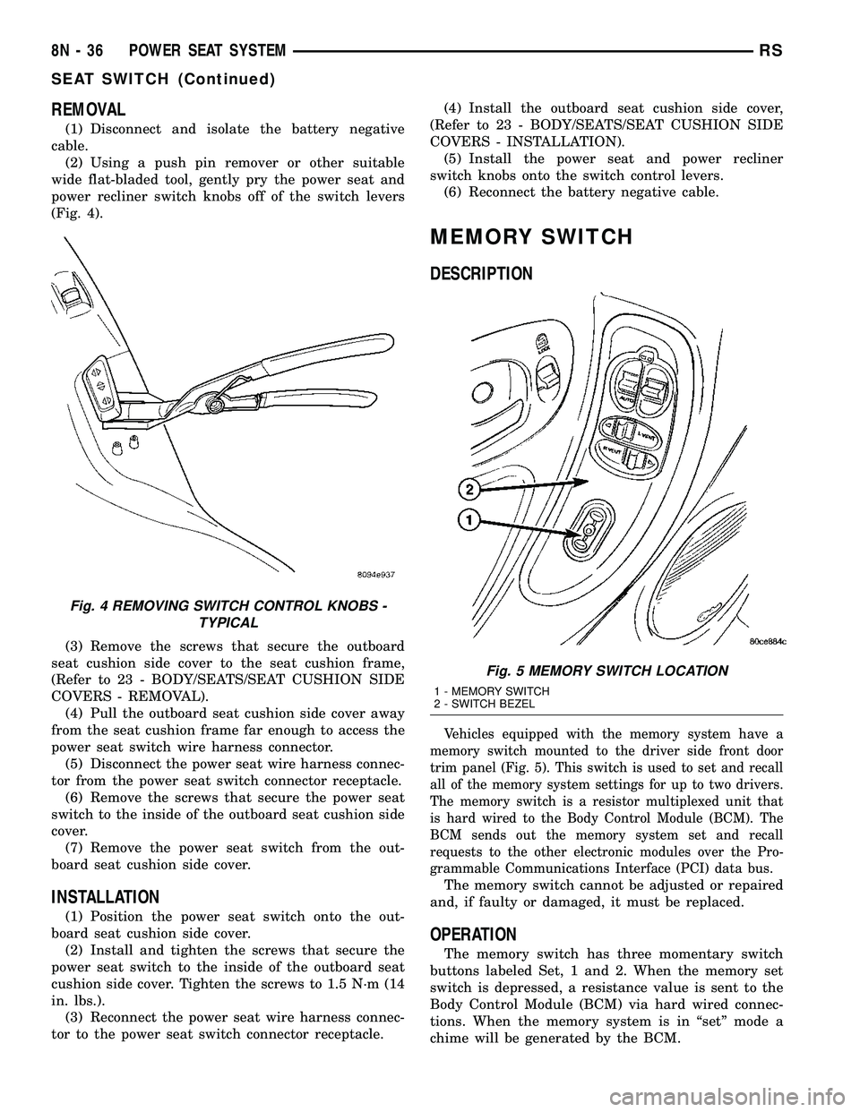
power recliner switch knobs off of the switch levers
(Fig. 4).
(3) Remove the screws that secure the outboard
seat cushion side cover to the seat cushion frame,
(Refer to 23 - BODY/SEATS/SEAT CUSHION SIDE
COVERS - REMOVAL).
(4) Pull the outboard seat cushion side cover away
from the seat cushion frame far enough to access the
power seat switch wire harness connector.
(5) Disconnect the power seat wire harness connec-
tor from the power seat switch connector receptacle.
(6) Remove the screws that secure the power seat
switch to the inside of the outboard seat cushion side
cover.
(7) Remove the power seat switch from the out-
board seat cushion side cover.
INSTALLATION
(1) Position the power seat switch onto the out-
board seat cushion side cover.
(2) Install and tighten the screws that secure the
power seat switch to the inside of the outboard seat
cushion side cover. Tighten the screws to 1.5 N´m (14
in. lbs.).
(3) Reconnect the power seat wire harness connec-
tor to the power seat switch connector receptacle.(4) Install the outboard seat cushion side cover,
(Refer to 23 - BODY/SEATS/SEAT CUSHION SIDE
COVERS - INSTALLATION).
(5) Install the power seat and power recliner
switch knobs onto the switch control levers.
(6) Reconnect the battery negative cable.
MEMORY SWITCH
DESCRIPTION
Vehicles equipped with the memory system have a
memory switch mounted to the driver side front door
trim panel (Fig. 5). This switch is used to set and recall
all of the memory system settings for up to two drivers.
The memory switch is a resistor multiplexed unit that
is hard wired to the Body Control Module (BCM). The
BCM sends out the memory system set and recall
requests to the other electronic modules over the Pro-
grammable Communications Interface (PCI) data bus.
The memory switch cannot be adjusted or repaired
and, if faulty or damaged, it must be replaced.
OPERATION
The memory switch has three momentary switch
buttons labeled Set, 1 and 2. When the memory set
switch is depressed, a resistance value is sent to the
Body Control Module (BCM) via hard wired connec-
tions. When the memory system is in ªsetº mode a
chime will be generated by the BCM.
Fig. 4 REMOVING SWITCH CONTROL KNOBS -
TYPICAL
Fig. 5 MEMORY SWITCH LOCATION
1 - MEMORY SWITCH
2 - SWITCH BEZEL
8N - 36 POWER SEAT SYSTEMRS
SEAT SWITCH (Continued)
Page 460 of 2339
DIAGNOSIS AND TESTING
MEMORY SWITCH
(1) Remove the memory switch from the drivers
door panel (Refer to 8 - ELECTRICAL/POWER
SEATS/MEMORY SET SWITCH - REMOVAL).
(2) Using an ohmmeter, check the continuity of the
memory select switch MUX circuit between the C2
wire harness connector for the Body Control Module
(BCM) and the wire harness connector for the mem-
ory switch. There should be continuity. If OK, go to
Step 3. If not OK, repair the open or shorted MUX
circuit as required.
(3) Using an ohmmeter, check the continuity of the
memory select switch return circuit between the C2
wire harness connector for the BCM and the wire
harness connector for the memory switch. There
should be continuity. If OK, go to Step 4. If not OK,
repair the open or shorted return circuit as required.
(4) Using an ohmmeter, test the resistances of the
memory switch, refer to the MEMORY SWITCH
TEST TABLE. If OK, (Refer to 8 - ELECTRICAL/
POWER SEATS - DIAGNOSIS AND TESTING -
MEMORY SYSTEM). If not OK, replace the memory
switch, (Refer to 8 - ELECTRICAL/POWER SEATS/
MEMORY SET SWITCH - REMOVAL).
MEMORY SWITCH TEST TABLE
MEMORY
SWITCH
POSITIONRESISTANCE
BETWEEN
PINSRESISTANCE
RANGE
(OHMS)
NEUTRAL 1&2 24650 5%
(24.65 k)
MEMORY 1 1&2 6850 5%
(6.85 k)
MEMORY 2 1&2 2100 5%
(2.10 k)
SET 1&2 4490 5%
(4.49 k)
REMOVAL
(1) Disconnect and isolate the battery negative
cable.
(2) Remove the front door trim panel switch bezel
from the driver side front door. Using a thin flat-
bladed pry tool, gently pry the switch bezel away
from the drivers door trim panel.
(3) Disconnect the memory switch wire harness
connector from the memory switch.
(4) Remove the two screws that secure the memory
switch to the back of the driver side front door trim
panel switch bezel.
(5) Remove the memory switch.
INSTALLATION
(1) Position the memory switch and install and
tighten the two screws that secure the memory
switch to the back of the driver side front door trim
panel switch bezel. Tighten the screws to 2.2 N´m (20
in. lbs.).
(2) Reconnect the memory switch wire harness
connector to the memory switch.
(3) Install the trim panel switch bezel onto the
driver side front door.
(4) Reconnect the battery negative cable.
POWER SEAT TRACK
DESCRIPTION
The power seat option includes an electrically oper-
ated power seat track located under the front seat. If
equipped with Memory System, the front power seat
track on the driver side of the vehicle also provides
the mounting location for the Memory Seat/Mirror
Module (MSMM). The power seat circuit breakers are
mounted on the rear of the power seat track, just
behind the seat rear trim panel. The lower half of the
power seat track is secured to the floor panel via four
studs and nuts that must be accessed from the
underside of the vehicle. Four bolts secure the bot-
tom of the seat cushion pan to the upper half of the
power seat track unit. Four additional bolts secure
the seat back frame to the power seat track unit.
The eight-way power seat track unit includes four
reversible electric motors that are secured to the
upper half of the track unit. Each motor moves the
seat adjuster through a combination of worm-drive
gearboxes and screw-type drive units. Each of the
four power seat track motors used on models
equipped with the optional memory system incorpo-
rate a position potentiometer integral to the motor
assembly, which electronically monitors the motor
position. This enables the memory system to function
by referencing the motor positions programmed into
the memory seat/mirror module.
The front and rear of the seat are operated by two
separate vertical adjustment motors. These motors
can be operated independently of each other, tilting
the entire seat assembly forward or rearward. They
can also be operated in unison by selecting the
proper power seat switch functions, which will raise
or lower the entire seat assembly. A third motor is
the horizontal adjustment motor, which moves the
seat track in the forward and aft directions. The
forth motor is the recliner adjustment motor, which
moves the seat back in the forward and rearward
directions.
The four-way power seat track unit includes two
reversible electric motors that are secured to the
RSPOWER SEAT SYSTEM8N-37
MEMORY SWITCH (Continued)
Page 462 of 2339

(2) Remove the appropriate seat from the vehicle
and place it on a clean work surface, (Refer to 23 -
BODY/SEATS/SEAT - REMOVAL).
(3) Remove the Memory Seat/Mirror Module
(MSMM) mounting fasteners (if equipped).
(4) Disconnect the MSMM electrical harness con-
nectors and remove the MSMM from the power seat
track (if equipped).
(5) Remove the front seat track rear cover, (Refer
to 23 - BODY/SEATS/SEAT TRACK REAR COVER -
REMOVAL).
(6) Remove the seat side cover and power seat
switch as an assembly (Refer to 23 - BODY/SEATS/
SEAT CUSHION SIDE COVERS - REMOVAL).
(7) Disconnect all electrical connectors connecting
the power seat track to the seat assembly.
(8) Pull the seat back trim cover up slightly to
access and remove the two seat back frame mounting
bolts and also remove two seat back recliner bolts.
(9) Remove four seat track mounting bolts from
the seat cushion pan.
(10) Remove the power seat track from the seat.INSTALLATION
(1) Position the seat cushion on the seat track.
(2) Install the four seat track retaining bolts in the
seat cushion pan. Torque the bolts to 28.5 N´m (21 ft-
lbs.).
(3) Position the seat back and install the two seat
back frame mounting bolts and the two seat back
recliner bolts. Torque the bolts to 55 N´m (40.5
ft-lbs.).
(4) Route and connect the electrical connectors
between the power seat track and the seat assembly.
(5) Install the seat side cover and power seat
switch as an assembly (Refer to 23 - BODY/SEATS/
SEAT CUSHION SIDE COVERS - INSTALLATION).
(6) Install the front seat track rear cover, (Refer to
23 - BODY/SEATS/SEAT TRACK REAR COVER -
INSTALLATION).
(7) Position the Memory Seat/Mirror Module
(MSMM) and connect the MSMM electrical connec-
tors (if equipped).
(8) Install the MSMM mounting fasteners (if
equipped).
(9) Install the seat assembly in the vehicle (Refer
to 23 - BODY/SEATS/SEAT - INSTALLATION).
(10) Connect the battery negative cable.
RSPOWER SEAT SYSTEM8N-39
POWER SEAT TRACK (Continued)
Page 492 of 2339
driver and the front seat passenger to the structure
of the instrument panel (Refer to 8 - ELECTRICAL/
RESTRAINTS/KNEE BLOCKER AIRBAG -
DESCRIPTION). The seat belt tensioners remove the
slack from the front seat belts to provide further
assurance that the driver and front seat passenger
are properly positioned and restrained for an airbag
deployment.
When the ORC monitors a problem in any of the
dual front airbag system circuits or components,
including the seat belt tensioners, it stores a Diag-
nostic Trouble Code (DTC) in its memory and sends
an electronic message to the EMIC to turn on the
airbag indicator. Proper testing of the supplemental
restraint system components, the Programmable
Communications Interface (PCI) data bus, the elec-
tronic message inputs to and outputs from the EMIC
or the ORC, as well as the retrieval or erasure of a
DTC from the ORC or the EMIC requires the use of
a scan tool. Refer to the appropriate diagnostic infor-
mation.
OCCUPANT CLASSIFICATION SYSTEM
The Occupant Classification System (OCS) auto-
matically suppresses or enables passenger airbag and
seat belt tensioner operation based upon whether or
not the passenger side front seat is occupied and, if
the seat is occupied, classifies the size of the occu-
pant and whether the seat is occupied by a child
seat.
The OCS has an Occupant Classification Module
(OCM) that monitors inputs from the seat weight
bladder pressure sensor under the passenger side
front seat cushion and from the belt tension sensor
on the passenger side front seat belt lower anchor.
Based upon those inputs the microprocessor within
the OCM classifies the occupant of the passenger
side front seat. The OCM then sends electronic occu-
pant classification messages to the ORC. The micro-
processor and programming of the ORC uses these
occupant classification messages to determine
whether to enable or disable the deployment circuits
for the passenger airbag and seat belt tensioner.
The OCS electrical circuits and components are
continuously monitored by the OCM, and the OCM is
continuously monitored by the ORC. A passenger air-
bag ON/OFF indicator is located in the instrument
panel center stack area. This indicator receives bat-
tery current whenever the ignition switch is in the
ON or START positions, and illuminates only when
the ORC pulls the indicator control circuit to ground.
The indicator illuminates for about seven seconds as
a bulb test each time the ignition switch is turned to
the ON or START positions. Following the bulb test,
the indicator is turned ON or OFF by the ORC based
upon the electronic occupant classification messagesreceived from the OCM. This indicator is illuminated
whenever the passenger airbag and seat belt ten-
sioner operation has been suppressed, and is turned
OFF whenever they are enabled or when the passen-
ger seat is classified as empty.
When the OCM monitors a problem in any of the
OCS circuits or components, it stores a fault code or
DTC in its memory circuit and sends an electronic
message to the ORC. The ORC then sends an elec-
tronic message to the EMIC to turn ON the airbag
indicator. If for any reason the OCM is unable to
classify the occupant it sends an electronic message
to the ORC, and the ORC suppresses passenger air-
bag and seat belt tensioner operation. Proper testing
of the OCS components, the Programmable Commu-
nications Interface (PCI) data bus, the electronic
message inputs to and outputs from the OCM, the
EMIC or the ORC, as well as the retrieval or erasure
of a DTC's, requires the use of a scan tool. Refer to
the appropriate diagnostic information.
WARNING
WARNINGS
Disconnect and isolate the battery negative
cable before beginning any airbag system com-
ponent diagnosis, testing, removal, or installa-
tion procedures. Allow system capacitor to
discharge for two minutes before beginning any
component testing or service. This will disable
the airbag system. Failure to disconnect the
battery negative cable may result in accidental
airbag deployment, personal injury, or death.
Do not place an intact undeployed airbag
face down on a solid surface. The airbag will
propel into the air if accidentally deployed and
may result in personal injury or death.
When carrying or handling an undeployed
airbag, the trim side (face) of the airbag should
be pointing towards the body to minimize pos-
sibility of injury if accidental deployment
occurs. Failure to do this may result in per-
sonal injury or death.
Replace airbag system components with
Mopartreplacement parts. Substitute parts
may appear interchangeable, but internal dif-
ferences may result in inferior occupant protec-
tion. Failure to do so may result in occupant
personal injury or death.
Wear safety glasses, rubber gloves, and long
sleeved clothing when cleaning powder residue
from vehicle after airbag deployment. Sodium
hydroxide powder residue emitted from a
deployed airbag can cause skin irritation.
Flush affected area with cool water if irritation
is experienced. If nasal or throat irritation is
RSRESTRAINTS8O-5
RESTRAINTS (Continued)
Page 512 of 2339
OCCUPANT CLASSIFICATION
MODULE
DESCRIPTION
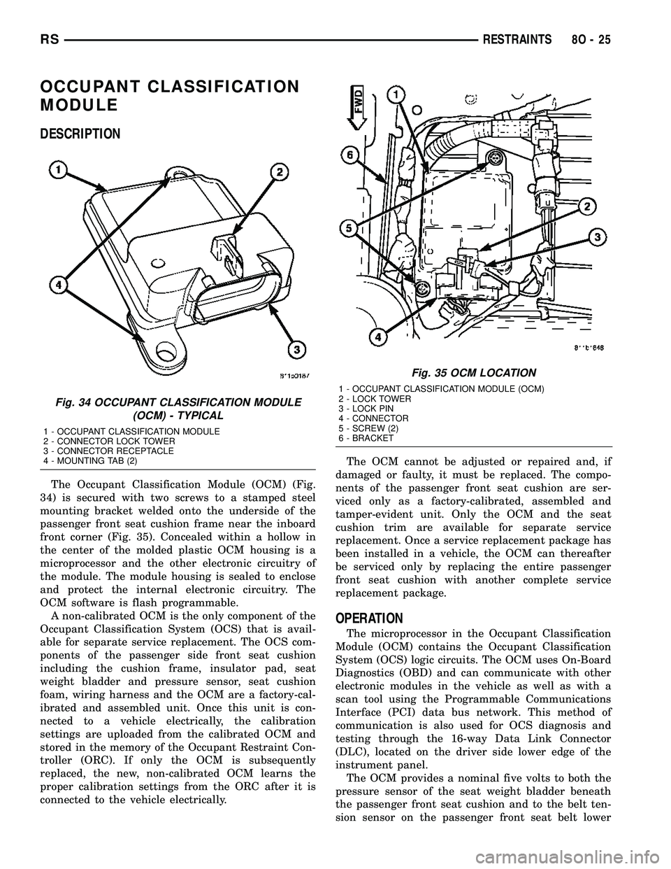
The Occupant Classification Module (OCM) (Fig.
34) is secured with two screws to a stamped steel
mounting bracket welded onto the underside of the
passenger front seat cushion frame near the inboard
front corner (Fig. 35). Concealed within a hollow in
the center of the molded plastic OCM housing is a
microprocessor and the other electronic circuitry of
the module. The module housing is sealed to enclose
and protect the internal electronic circuitry. The
OCM software is flash programmable.
A non-calibrated OCM is the only component of the
Occupant Classification System (OCS) that is avail-
able for separate service replacement. The OCS com-
ponents of the passenger side front seat cushion
including the cushion frame, insulator pad, seat
weight bladder and pressure sensor, seat cushion
foam, wiring harness and the OCM are a factory-cal-
ibrated and assembled unit. Once this unit is con-
nected to a vehicle electrically, the calibration
settings are uploaded from the calibrated OCM and
stored in the memory of the Occupant Restraint Con-
troller (ORC). If only the OCM is subsequently
replaced, the new, non-calibrated OCM learns the
proper calibration settings from the ORC after it is
connected to the vehicle electrically.The OCM cannot be adjusted or repaired and, if
damaged or faulty, it must be replaced. The compo-
nents of the passenger front seat cushion are ser-
viced only as a factory-calibrated, assembled and
tamper-evident unit. Only the OCM and the seat
cushion trim are available for separate service
replacement. Once a service replacement package has
been installed in a vehicle, the OCM can thereafter
be serviced only by replacing the entire passenger
front seat cushion with another complete service
replacement package.
OPERATION
The microprocessor in the Occupant Classification
Module (OCM) contains the Occupant Classification
System (OCS) logic circuits. The OCM uses On-Board
Diagnostics (OBD) and can communicate with other
electronic modules in the vehicle as well as with a
scan tool using the Programmable Communications
Interface (PCI) data bus network. This method of
communication is also used for OCS diagnosis and
testing through the 16-way Data Link Connector
(DLC), located on the driver side lower edge of the
instrument panel.
The OCM provides a nominal five volts to both the
pressure sensor of the seat weight bladder beneath
the passenger front seat cushion and to the belt ten-
sion sensor on the passenger front seat belt lower
Fig. 34 OCCUPANT CLASSIFICATION MODULE
(OCM) - TYPICAL
1 - OCCUPANT CLASSIFICATION MODULE
2 - CONNECTOR LOCK TOWER
3 - CONNECTOR RECEPTACLE
4 - MOUNTING TAB (2)
Fig. 35 OCM LOCATION
1 - OCCUPANT CLASSIFICATION MODULE (OCM)
2 - LOCK TOWER
3 - LOCK PIN
4 - CONNECTOR
5 - SCREW (2)
6 - BRACKET
RSRESTRAINTS8O-25
Page 513 of 2339
anchor. The OCM then monitors the return voltage
from each of the sensors. The bladder pressure sen-
sor input allows the OCM to determine whether the
passenger front seat is occupied and the relative size
of the occupant by providing a weight-sensing refer-
ence to the load on the seat cushion. The belt tension
sensor provides an additional logic input to the OCM
microprocessor that allows it to distinguish between
the lower seat belt cinch loads of a belted occupant
and the higher loads associated with a belted child
seat.
Pre-programmed decision algorithms and OCS cal-
ibration allow the OCM microprocessor to determine
when the seat cushion load as signaled by the blad-
der pressure sensor and the seat belt cinch load as
signaled by the belt tension sensor indicate that pas-
senger airbag protection is appropriate. When the
programmed conditions are met, the OCM sends the
proper electronic occupant classification messages
over the PCI data bus to the Occupant Restraint
Controller (ORC), and the ORC enables or disables
the deployment circuits for the passenger front sup-
plemental restraints. The ORC also provides a con-
trol output for the Passenger Airbag Disabled (PAD)
indicator in the instrument panel center stack, based
upon the electronic occupant classification messages
it receives from the OCM.
The OCM microprocessor continuously monitors all
of the OCS electrical circuits and components to
determine the system readiness. If the OCM detects
a monitored system fault, it sets an active and stored
Diagnostic Trouble Code (DTC) and sends the appro-
priate electronic messages to the ORC over the PCI
data bus. Then the ORC sets a DTC and sends mes-
sages to control the airbag indicator operation
accordingly. An active fault only remains for the
duration of the fault, or in some cases for the dura-
tion of the current ignition switch cycle, while a
stored fault causes a DTC to be stored in memory by
the OCM and the ORC. For some DTC's, if a fault
does not recur for a number of ignition cycles, the
OCM will automatically erase the stored DTC. For
other internal faults, the stored DTC is latched for-
ever.
The OCM receives battery current from an IPM
high side driver (Run/Start). The OCM receives
ground through a ground circuit of the body wire
harness, which it shares with the ORC. These con-
nections allow the OCM to be operational whenever
the ignition switch is in the Start or ON positions.
To diagnose and test the OCS, use a scan tool and
the appropriate diagnostic information.
REMOVAL
Once any of the original factory-installed compo-
nents except the Occupant Classification Module(OCM) have been replaced with the service replace-
ment package components, the OCM can only be ser-
viced by replacing the entire passenger front seat
cushion unit with another complete service replace-
ment package (Refer to 23 - BODY/SEATS/SEAT
CUSHION - FRONT - REMOVAL).
WARNING: Never replace both the Occupant
Restraint Controller (ORC) and the Occupant Clas-
sification Module (OCM) at the same time. If both
require replacement, replace one, then perform the
Airbag System test (Refer to 8 - ELECTRICAL/RE-
STRAINTS - DIAGNOSIS AND TESTING - AIRBAG
SYSTEM) before replacing the other. Both the ORC
and the OCM store Occupant Classification System
(OCS) calibration data, which they transfer to one
another when one of them is replaced. If both are
replaced at the same time, an irreversible fault will
be set in both modules and the OCS may malfunc-
tion and result in personal injury or death.
(1) Disconnect and isolate the battery negative
cable.
(2)
WARNING: Wait two minutes for the airbag system
reserve capacitor to discharge before beginning
any airbag system or component service. Failure to
do so may result in accidental airbag deployment,
personal injury or death.
(3) Reach under the front edge of the passenger
side front seat cushion to access and remove the lock
pin from the connector lock tower on the Occupant
Classification Module (OCM) (Fig. 36).
(4) Disconnect the passenger front seat wire har-
ness connector for the OCM.
(5) Remove the two screws that secure the OCM to
the OCM bracket.
(6) Remove the OCM from under the passenger
front seat.
INSTALLATION
WARNING: To avoid personal injury or death on
vehicles equipped with the Occupant Classification
System (OCS), only the Occupant Classification
Module (OCM) and the seat cushion trim may be
serviced separately. All other components of the
passenger front seat cushion must be serviced only
as a complete factory-calibrated, assembled and
tamper-evident service replacement package.
Once any of the original factory-installed compo-
nents except the OCM have been replaced with the
service replacement package components, the OCM
can only be serviced by replacing the entire passen-
8O - 26 RESTRAINTSRS
OCCUPANT CLASSIFICATION MODULE (Continued)
Page 515 of 2339
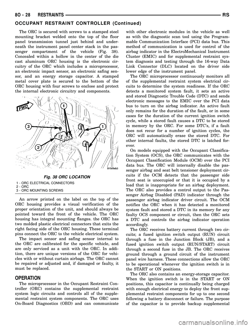
The ORC is secured with screws to a stamped steel
mounting bracket welded onto the top of the floor
panel transmission tunnel just behind and under-
neath the instrument panel center stack in the pas-
senger compartment of the vehicle (Fig. 38).
Concealed within a hollow in the center of the die
cast aluminum ORC housing is the electronic cir-
cuitry of the ORC which includes a microprocessor,
an electronic impact sensor, an electronic safing sen-
sor, and an energy storage capacitor. A stamped
metal cover plate is secured to the bottom of the
ORC housing with four screws to enclose and protect
the internal electronic circuitry and components.
An arrow printed on the label on the top of the
ORC housing provides a visual verification of the
proper orientation of the unit, and should always be
pointed toward the front of the vehicle. The ORC
housing has integral mounting flanges. the ORC has
two molded plastic electrical connectors that exits the
right facing side of the ORC housing. These terminal
pins connect the ORC to the vehicle electrical system.
The impact sensor and safing sensor internal to
the ORC are calibrated for the specific vehicle, and
are only serviced as a unit with the ORC. In addi-
tion, there are unique versions of the ORC for vehi-
cles with or without curtain airbags. The ORC cannot
be repaired or adjusted and, if damaged or faulty, it
must be replaced.
OPERATION
The microprocessor in the Occupant Restraint Con-
troller (ORC) contains the supplemental restraint
system logic circuits and controls all of the supple-
mental restraint system components. The ORC uses
On-Board Diagnostics (OBD) and can communicatewith other electronic modules in the vehicle as well
as with the diagnostic scan tool using the Program-
mable Communication Interface (PCI) data bus. This
method of communication is used for control of the
airbag indicator in the ElectroMechanical Instrument
Cluster (EMIC) and for supplemental restraint sys-
tem diagnosis and testing through the 16-way Data
Link Connector (DLC) located on the driver side
lower edge of the instrument panel.
The ORC microprocessor continuously monitors all
of the supplemental restraint system electrical cir-
cuits to determine the system readiness. If the ORC
detects a monitored system fault, it sets an active
and stored Diagnostic Trouble Code (DTC) and sends
electronic messages to the EMIC over the PCI data
bus to turn on the airbag indicator. An active fault
only remains for the duration of the fault, or in some
cases for the duration of the current ignition switch
cycle, while a stored fault causes a DTC to be stored
in memory by the ORC. For some DTC's, if a fault
does not recur for a number of ignition cycles, the
ORC will automatically erase the stored DTC. For
other internal faults, the stored DTC is latched for-
ever.
On models equipped with the Occupant Classifica-
tion System (OCS), the ORC communicates with the
Occupant Classification Module (OCM) over the PCI
data bus. The ORC will internally disable the pas-
senger airbag and seat belt tensioner deployment cir-
cuits if the OCM detects that the passenger side
front seat is unoccupied or that it is occupied by a
load that is inappropriate for an airbag deployment.
The ORC also provides a control output to the Pas-
senger Airbag Disabled (PAD) indicator through the
passenger airbag indicator driver circuit. The OCM
notifies the ORC when it has detected a monitored
system fault and stored a DTC in its memory for any
faulty OCS component or circuit, then the ORC sets
a DTC and controls the airbag indicator operation
accordingly.
The ORC receives battery current through two cir-
cuits; a fused ignition switch output (RUN) circuit
through a fuse in the Junction Block (JB), and a
fused ignition switch output (RUN/START) circuit
through a second fuse in the JB. The ORC receives
ground through a ground circuit of the instrument
panel wire harness. These connections allow the ORC
to be operational whenever the ignition switch is in
the START or ON positions.
The ORC also contains an energy-storage capacitor.
When the ignition switch is in the START or ON
positions, this capacitor is continually being charged
with enough electrical energy to deploy the front sup-
plemental restraint components for up to one second
following a battery disconnect or failure. The purpose
of the capacitor is to provide backup supplemental
Fig. 38 ORC LOCATION
1 - ORC ELECTRICAL CONNECTORS
2 - ORC
3 - ORC MOUNTING SCREWS
8O - 28 RESTRAINTSRS
OCCUPANT RESTRAINT CONTROLLER (Continued)
Page 583 of 2339
Component Page
Ignition Coil......................... 8W-30
Ignition Switch....................... 8W-10
Impact Sensors....................... 8W-43
Inlet Air Temperature Sensor............ 8W-30
Instrument Cluster.................... 8W-40
Instrument Panel Switch
Bank.................. 8W-43, 44, 52, 53, 63
Integrated Power Module............... 8W-10
Knock Sensor........................ 8W-30
Lamp Assemblies...................... 8W-51
License Lamp..................... 8W-51, 61
Lift Pump Motor...................... 8W-30
Lift Pump Relay...................... 8W-30
Liftgate Ajar Switch................ 8W-39, 61
Liftgate Cinch/Release Motor............ 8W-61
Liftgate Flood Lamps.................. 8W-44
Liftgate Pinch Sensors................. 8W-61
Low Beam Lamps..................... 8W-50
Manifold Absolute Pressure Sensor........ 8W-30
Mass Air Flow Sensor.................. 8W-30
Memory Seat/Mirror/Adjustable Pedals
Module...................... 8W-56, 62, 63
Memory Set Switch.................... 8W-63
Message Center.................... 8W-40, 46
Mode Door Actuator................... 8W-42
Multi-Function Switch............ 8W-50, 52, 53
Natural Vacuum Leak Detection Assembly . . 8W-30
Occupant Classification Module.......... 8W-43
Occupant Restraint Controller........... 8W-43
Overhead Console..................... 8W-49
Oxygen Sensors....................... 8W-30
Park Assist Display.................... 8W-56
Park Assist Module.................... 8W-56
Park Assist Sensors.................... 8W-56
Park Lamp Relay..................... 8W-10
Park Lamps.......................... 8W-50
Park/Turn Signal Lamps................ 8W-50
Parking Brake Switch.................. 8W-40
Power Folding Mirror Switch............ 8W-62
Power Liftgate Module................. 8W-61
Power Liftgate Motor.................. 8W-61
Power Mirror Switch................... 8W-62
Power Mirrors........................ 8W-62
Power Outlets........................ 8W-41
Power Seat Circuit Breaker.............. 8W-10
Power Seat Motors.................... 8W-63
Power Seat Position Sensors............. 8W-63
Power Seat Switches................... 8W-63
Power Window Circuit Breaker........... 8W-10
Power Window Motors.................. 8W-60
Power Window Switches................ 8W-60
Powertrain Control Module........... 8W-30, 31
PTCs............................... 8W-10
Radiator Fan Relaies................... 8W-42Component Page
Radiator Fans........................ 8W-42
Radio............................... 8W-47
Reading Lamps....................... 8W-44
Rear A/C-Heater Unit.................. 8W-42
Rear Auto Temp Control Switch.......... 8W-42
Rear Blower Control Switches............ 8W-42
Rear Blower Motor Power Module......... 8W-42
Rear Dome Lamp..................... 8W-44
Rear Intrusion Sensor.................. 8W-39
Rear Mode Motor..................... 8W-42
Rear Temperature Motor................ 8W-42
Rear View Mirror................ 8W-49, 55, 62
Rear Window Defogger Grid............. 8W-48
Rear Wiper Motor..................... 8W-53
Recirculation Door Actuator............. 8W-42
Remote Radio Switches................. 8W-47
Repeater Lamps...................... 8W-52
Seat Belt Switches.................... 8W-43
Seat Belt Tensioners................... 8W-43
Seat Weight Sensor.................... 8W-43
Sentry Key Remote Entry Module......... 8W-39
Siren............................... 8W-39
Sliding Door Control Modules............ 8W-61
Sliding Door Latch Sensing Switches...... 8W-61
Sliding Door Lock Motors............... 8W-61
Sliding Door Motors................... 8W-61
Speakers............................ 8W-47
Speed Control Servo................... 8W-33
Speed Control Switches................. 8W-33
Speed Sensors........................ 8W-31
Splices.............................. 8W-70
Starter Motor........................ 8W-21
Starter Motor Relay................... 8W-21
Sunroof Module....................... 8W-64
Sunroof Switch....................... 8W-64
Thatcham Alarm Indicator.............. 8W-39
Thatcham Alarm Module................ 8W-39
Throttle Position Sensor................ 8W-30
Traction Control Switch................. 8W-35
Trailer Tow Connector.................. 8W-54
Transmission Control Module............ 8W-31
Transmission Control Relay............. 8W-31
Transmission Range Sensor.............. 8W-31
Transmission Solenoid/Pressure Switch
Assembly.......................... 8W-31
Turn Signal Lamps.................... 8W-52
Vehicle Speed Sensor................... 8W-30
Vent Motors.......................... 8W-60
Visor/Vanity Lamps.................... 8W-44
Washer Fluid Level Switch.............. 8W-53
Washer Pump Motor................... 8W-53
Water In Fuel Sensor.................. 8W-30
Wheel Speed Sensors................... 8W-35
Wiper Module........................ 8W-53
8W - 02 - 2 8W-02 COMPONENT INDEXRS
Page 585 of 2339
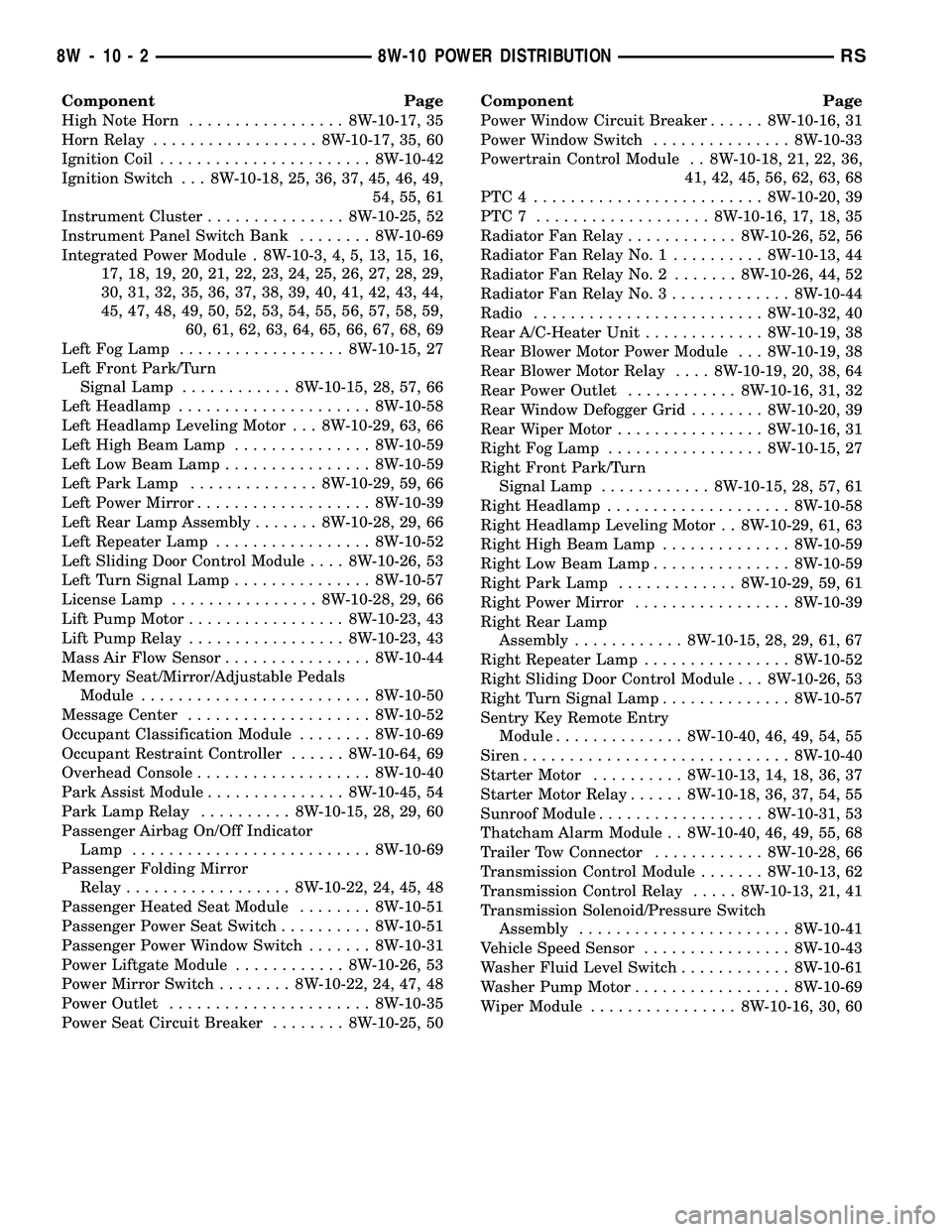
Component Page
High Note Horn................. 8W-10-17, 35
Horn Relay.................. 8W-10-17, 35, 60
Ignition Coil....................... 8W-10-42
Ignition Switch . . . 8W-10-18, 25, 36, 37, 45, 46, 49,
54, 55, 61
Instrument Cluster............... 8W-10-25, 52
Instrument Panel Switch Bank........ 8W-10-69
Integrated Power Module . 8W-10-3, 4, 5, 13, 15, 16,
17, 18, 19, 20, 21, 22, 23, 24, 25, 26, 27, 28, 29,
30, 31, 32, 35, 36, 37, 38, 39, 40, 41, 42, 43, 44,
45, 47, 48, 49, 50, 52, 53, 54, 55, 56, 57, 58, 59,
60, 61, 62, 63, 64, 65, 66, 67, 68, 69
Left Fog Lamp.................. 8W-10-15, 27
Left Front Park/Turn
Signal Lamp............ 8W-10-15, 28, 57, 66
Left Headlamp..................... 8W-10-58
Left Headlamp Leveling Motor . . . 8W-10-29, 63, 66
Left High Beam Lamp............... 8W-10-59
Left Low Beam Lamp................ 8W-10-59
Left Park Lamp.............. 8W-10-29, 59, 66
Left Power Mirror................... 8W-10-39
Left Rear Lamp Assembly....... 8W-10-28, 29, 66
Left Repeater Lamp................. 8W-10-52
Left Sliding Door Control Module.... 8W-10-26, 53
Left Turn Signal Lamp............... 8W-10-57
License Lamp................ 8W-10-28, 29, 66
Lift Pump Motor................. 8W-10-23, 43
Lift Pump Relay................. 8W-10-23, 43
Mass Air Flow Sensor................ 8W-10-44
Memory Seat/Mirror/Adjustable Pedals
Module......................... 8W-10-50
Message Center.................... 8W-10-52
Occupant Classification Module........ 8W-10-69
Occupant Restraint Controller...... 8W-10-64, 69
Overhead Console................... 8W-10-40
Park Assist Module............... 8W-10-45, 54
Park Lamp Relay.......... 8W-10-15, 28, 29, 60
Passenger Airbag On/Off Indicator
Lamp.......................... 8W-10-69
Passenger Folding Mirror
Relay.................. 8W-10-22, 24, 45, 48
Passenger Heated Seat Module........ 8W-10-51
Passenger Power Seat Switch.......... 8W-10-51
Passenger Power Window Switch....... 8W-10-31
Power Liftgate Module............ 8W-10-26, 53
Power Mirror Switch........ 8W-10-22, 24, 47, 48
Power Outlet...................... 8W-10-35
Power Seat Circuit Breaker........ 8W-10-25, 50Component Page
Power Window Circuit Breaker...... 8W-10-16, 31
Power Window Switch............... 8W-10-33
Powertrain Control Module . . 8W-10-18, 21, 22, 36,
41, 42, 45, 56, 62, 63, 68
PTC4 ......................... 8W-10-20, 39
PTC7 ................... 8W-10-16, 17, 18, 35
Radiator Fan Relay............ 8W-10-26, 52, 56
Radiator Fan Relay No. 1.......... 8W-10-13, 44
Radiator Fan Relay No. 2....... 8W-10-26, 44, 52
Radiator Fan Relay No. 3............. 8W-10-44
Radio......................... 8W-10-32, 40
Rear A/C-Heater Unit............. 8W-10-19, 38
Rear Blower Motor Power Module . . . 8W-10-19, 38
Rear Blower Motor Relay.... 8W-10-19, 20, 38, 64
Rear Power Outlet............ 8W-10-16, 31, 32
Rear Window Defogger Grid........ 8W-10-20, 39
Rear Wiper Motor................ 8W-10-16, 31
Right Fog Lamp................. 8W-10-15, 27
Right Front Park/Turn
Signal Lamp............ 8W-10-15, 28, 57, 61
Right Headlamp.................... 8W-10-58
Right Headlamp Leveling Motor . . 8W-10-29, 61, 63
Right High Beam Lamp.............. 8W-10-59
Right Low Beam Lamp............... 8W-10-59
Right Park Lamp............. 8W-10-29, 59, 61
Right Power Mirror................. 8W-10-39
Right Rear Lamp
Assembly............ 8W-10-15, 28, 29, 61, 67
Right Repeater Lamp................ 8W-10-52
Right Sliding Door Control Module . . . 8W-10-26, 53
Right Turn Signal Lamp.............. 8W-10-57
Sentry Key Remote Entry
Module.............. 8W-10-40, 46, 49, 54, 55
Siren............................. 8W-10-40
Starter Motor.......... 8W-10-13, 14, 18, 36, 37
Starter Motor Relay...... 8W-10-18, 36, 37, 54, 55
Sunroof Module.................. 8W-10-31, 53
Thatcham Alarm Module . . 8W-10-40, 46, 49, 55, 68
Trailer Tow Connector............ 8W-10-28, 66
Transmission Control Module....... 8W-10-13, 62
Transmission Control Relay..... 8W-10-13, 21, 41
Transmission Solenoid/Pressure Switch
Assembly....................... 8W-10-41
Vehicle Speed Sensor................ 8W-10-43
Washer Fluid Level Switch............ 8W-10-61
Washer Pump Motor................. 8W-10-69
Wiper Module................ 8W-10-16, 30, 60
8W - 10 - 2 8W-10 POWER DISTRIBUTIONRS