ipm CHRYSLER VOYAGER 2005 Owner's Manual
[x] Cancel search | Manufacturer: CHRYSLER, Model Year: 2005, Model line: VOYAGER, Model: CHRYSLER VOYAGER 2005Pages: 2339, PDF Size: 59.69 MB
Page 171 of 2339

SPECIFICATIONS
BRAKE ROTOR
When refacing a rotor, the required TIR (Total
Indicator Reading) and thickness variation limitsMUST BE MAINTAINED. Extreme care in the oper-
ation of rotor turning equipment is required.
LIMITS/SPECIFICATIONS
Braking Rotor Rotor ThicknessMinimum Rotor
ThicknessRotor Thickness
VariationRotor Runout*
Front - TRW27.87±28.13 mm
1.097-1.107 in.25.3 mm
0.996 in.0.009 mm
0.0004 in.0.075 mm
0.0030 in.
Front - Continental
Teves27.90±28.10 mm
1.098-1.106 in.25.3 mm
0.996 in.0.008 mm
0.0003 in.0.100 mm
0.0039 in.
Rear12.4±12.6 mm
0.488 -0.496 in.11.25 mm
0.443 in.0.013 mm
0.0005 in.0.14 mm
0.0055 in.
*
TIR Total Indicator Reading (Measured On Vehicle)
BRAKE ROTOR - EXPORT
NOTE: Use the following information on all 4 wheel
disc brake vehicles that are equipped with BR3
sales code.When refacing a rotor, the required TIR (Total
Indicator Reading) and thickness variation limits
MUST BE MAINTAINED. Extreme care in the oper-
ation of rotor turning equipment is required.
LIMITS/SPECIFICATIONS
Brake Rotor Rotor ThicknessMinimum Rotor
ThicknessRotor Thickness
VariationRotor Runout*
Front27.9-28.1 mm
1.098 -1.106 in.26.5 mm
1.043 in0.010 mm
0.0004 in.0.080 mm
0.0031 in.
Rear12.4-12.6 mm
0.488-0.496 in.11.25 mm
0.443 in.0.013 mm
0.0005 in.0.14 mm
0.0055 in.
* TIR Total Indicator Reading (Measured On Vehicle)
5 - 60 BRAKES - BASERS
ROTOR (Continued)
Page 201 of 2339
CAUTION
The ABS uses an electronic control module, the
CAB. This module is designed to withstand normal
current draws associated with vehicle operation.
Care must be taken to avoid overloading the CAB
circuits.
CAUTION: In testing for open or short circuits, do
not ground or apply voltage to any of the circuits
unless instructed to do so for a diagnostic proce-
dure.
CAUTION: These circuits should only be tested
using a high impedance multi-meter or the DRBIIIT
scan tool as described in this section. Power
should never be removed or applied to any control
module with the ignition in the ON position. Before
removing or connecting battery cables, fuses, or
connectors, always turn the ignition to the OFF
position.
CAUTION: The CAB 24-way connector should never
be connected or disconnected with the ignition
switch in the ON position.
CAUTION: This vehicle utilizes active wheel speed
sensors. Do not apply voltage to wheel speed sen-
sors at any time.
CAUTION: Use only factory wiring harnesses. Do
not cut or splice wiring to the brake circuits. The
addition of aftermarket electrical equipment (car
phone, radar detector, citizen band radio, trailer
lighting, trailer brakes, etc.) on a vehicle equipped
with antilock brakes may affect the function of the
antilock brake system.
CAUTION: When performing any service procedure
on a vehicle equipped with ABS, do not apply a
12-volt power source to the ground circuit of the
pump motor in the HCU. Doing this will damage the
pump motor and will require replacement of the
entire HCU.
CAUTION: An attempt to remove or disconnect cer-
tain system components may result in improper
system operation. Only those components with
approved removal and installation procedures in
this manual should be serviced.
CAUTION: If welding work is to be performed on the
vehicle using an electric arc welder, the CAB con-nector should be disconnected during the welding
operation.
CAUTION: Many components of the ABS System
are not serviceable and must be replaced as an
assembly. Do not disassemble any component
which is not designed to be serviced.
CAUTION: Only the recommended jacking or hoist-
ing positions for this vehicle are to be used when-
ever it is necessary to lift a vehicle. Failure to raise
a vehicle from the recommended locations could
result in lifting a vehicle by the hydraulic control
unit mounting bracket. Lifting a vehicle by the
hydraulic control unit mounting bracket will result
in damage to the mounting bracket and the hydrau-
lic control unit.
CAUTION: Brake fluid will damage painted surfaces.
If brake fluid is spilled on any painted surface,
wash off with water immediately.
STANDARD PROCEDURE - ANTILOCK BRAKE
SYSTEM BLEEDING
The base brake's hydraulic system must be bled
anytime air enters the hydraulic system. The ABS
though, particularly the ICU (HCU), should only be
bled when the HCU is replaced or removed from the
vehicle. The ABS must always be bled anytime it is
suspected that the HCU has ingested air. Under
most circumstances that require the bleeding of the
brakes hydraulic system, only the base brake
hydraulic system needs to be bled.
It is important to note that excessive air in the
brake system will cause a soft or spongy feeling
brake pedal.
During the brake bleeding procedure, be sure the
brake fluid level remains close to the FULL level in
the master cylinder fluid reservoir. Check the fluid
level periodically during the bleeding procedure and
add DOT 3 brake fluid as required.
The ABS must be bled as two independent braking
systems. The non-ABS portion of the brake system
with ABS is to be bled the same as any non-ABS sys-
tem.
The ABS portion of the brake system must be bled
separately. Use the following procedure to properly
bleed the brake hydraulic system including the ABS.
BLEEDING
When bleeding the ABS system, the following
bleeding sequence must be followed to insure com-
plete and adequate bleeding.
5 - 90 BRAKES - ABSRS
BRAKES - ABS (Continued)
Page 218 of 2339
(21) Bleed the Base and ABS brake hydraulic sys-
tems (Refer to 5 - BRAKES - STANDARD PROCE-
DURE).
(22) Road test vehicle to ensure proper operation
of the base and antilock brake systems.
INSTALLATION - RHD
(1) Install the ICU on the mounting bracket (Fig.
21). Install the 3 bolts (Fig. 21) attaching the ICU to
the mounting bracket. Tighten the 3 mounting bolts
to a torque of 11 N´m (97 in. lbs.).
CAUTION: The ICU mounting bracket to front sus-
pension cradle mounting bolts have a unique corro-
sion protection coating and a special aluminum
washer. For this reason, only the original, or origi-
nal equipment Mopar replacement bolts can be
used to mount the ICU bracket to the front suspen-
sion crossmember.
(2) Install the ICU and its mounting bracket as an
assembly on the front suspension crossmember.
Install the 3 bolts attaching the ICU bracket to the
crossmember (Fig. 20). Tighten the 3 mounting bolts
to a torque of 28 N´m (250 in. lbs.).
CAUTION: Because of the flexible section in the pri-
mary and secondary brake tubes, and the brake
tubes between the HCU and the proportioning
valve, the brake tubes must be held in proper ori-
entation when tightened and torqued. These tubes
must not contact each other or other vehicle com-
ponents when installed. Also, after the brake tubes
are installed on the HCU, ensure all spacer clips are
reinstalled on the brake tubes.
CAUTION: When installing the chassis brake tubes
on the HCU valve block, they must be located cor-
rectly in the valve block to ensure proper ABS oper-
ation. Refer to (Fig. 19) for the correct chassis
brake tube locations.
NOTE: The chassis brake tube attachment locations
to the HCU, are marked on the bottom of the ICU
mounting bracket.
(3) Install the 6 chassis brake tubes into their cor-
rect port locations on the HCU valve block as shown
in (Fig. 19). Tighten the tube nuts to a torque of 17
N´m (145 in. lbs.).
NOTE: Before installing the 24-way connector in the
CAB be sure the seal is properly installed in the
connector.(4) Install the 24-way connector (Fig. 17) on the
CAB using the following procedure. Position the
24-way connector in the socket of the CAB and care-
fully push it down as far as possible. When connector
is fully seated by hand into the CAB socket, push in
the connector lock (Fig. 18). This will pull the connec-
tor into the socket of the CAB and lock it in the
installed position.
NOTE: The CAB wiring harness must be clipped to
the ICU mounting bracket. This will ensure the wir-
ing harness is properly routed and does not contact
the brake tubes or the body of the vehicle.
(5) Clip the cab wiring harness (Fig. 17) to the
ICU mounting bracket.
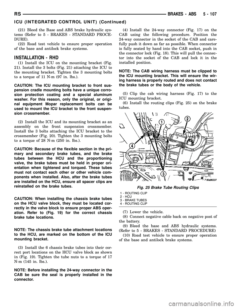
(6) Install the routing clips (Fig. 25) on the brake
tubes.
(7) Lower the vehicle.
(8) Connect negative cable back on negative post of
the battery.
(9) Bleed the base and ABS hydraulic systems.
(Refer to 5 - BRAKES - STANDARD PROCEDURE)
(10) Road test vehicle to ensure proper operation
of the base and antilock brake systems.
Fig. 25 Brake Tube Routing Clips
1 - ROUTING CLIP
2 - HCU
3 - BRAKE TUBES
4 - ROUTING CLIP
RSBRAKES - ABS5 - 107
ICU (INTEGRATED CONTROL UNIT) (Continued)
Page 220 of 2339
COOLING
TABLE OF CONTENTS
page page
COOLING
DESCRIPTION
DESCRIPTION - COOLING SYSTEM........1
DESCRIPTION - HOSE CLAMPS...........1
OPERATION
OPERATION - COOLING SYSTEM.........2
OPERATION - HOSE CLAMPS............2
DIAGNOSIS AND TESTING
DIAGNOSIS AND TESTING - COOLING
SYSTEM LEAK TEST....................2
DIAGNOSIS AND TESTING - COOLING
SYSTEM FLOW CHECK.................3
DIAGNOSIS AND TESTING - COOLING
SYSTEM AERATION....................4
DIAGNOSIS AND TESTING - COOLING
SYSTEM DEAERATION..................4
STANDARD PROCEDURE
STANDARD PROCEDURE - COOLING
SYSTEM DRAINING....................4STANDARD PROCEDURE - COOLING
SYSTEM FILLING......................4
STANDARD PROCEDURE - ADDING
ADDITIONAL COOLANT.................4
STANDARD PROCEDURE - COOLANT
LEVEL CHECK........................4
SPECIFICATIONS
ACCESSORY DRIVE BELT TENSION.......5
TORQUE.............................5
SPECIAL TOOLS
COOLING SYSTEM.....................6
ACCESSORY DRIVE.......................7
ENGINE...............................13
TRANSMISSION.........................38
COOLING
DESCRIPTION
DESCRIPTION - COOLING SYSTEM
The cooling system components consist of a radia-
tor, electric fan motors, shroud, pressure cap, thermo-
stat, transmission oil cooler, water pump, hoses,
clamps, coolant, and a coolant reserve system to com-
plete the circuit.
DESCRIPTION - HOSE CLAMPS
The cooling system uses spring type hose clamps.
If a spring type clamp replacement is necessary,
replace with the original Mopartequipment spring
type clamp.
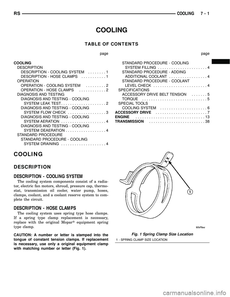
CAUTION: A number or letter is stamped into the
tongue of constant tension clamps. If replacement
is necessary, use only a original equipment clamp
with matching number or letter (Fig. 1).
Fig. 1 Spring Clamp Size Location
1 - SPRING CLAMP SIZE LOCATION
RSCOOLING7-1
Page 221 of 2339
OPERATION
OPERATION - COOLING SYSTEM
The engine cooling systems primary purpose is to
maintain engine temperature in a range that will
provide satisfactory engine performance and emission
levels under all expected driving conditions. It also
provides hot water (coolant) for heater performance
and cooling for automatic transmission oil. It does
this by transferring heat from engine metal to cool-
ant, moving this heated coolant to the radiator, and
then transferring this heat to the ambient air.
²When engine is cold: thermostat is closed, cool-
ing system has no flow through the radiator. The
coolant bypass flows through the engine only.
²When engine is warm: thermostat is open, cool-
ing system has bypass flow and coolant flow through
radiator.
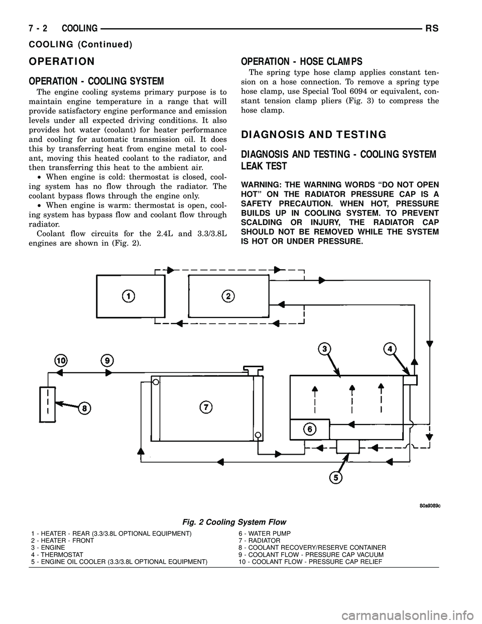
Coolant flow circuits for the 2.4L and 3.3/3.8L
engines are shown in (Fig. 2).
OPERATION - HOSE CLAMPS
The spring type hose clamp applies constant ten-
sion on a hose connection. To remove a spring type
hose clamp, use Special Tool 6094 or equivalent, con-
stant tension clamp pliers (Fig. 3) to compress the
hose clamp.
DIAGNOSIS AND TESTING
DIAGNOSIS AND TESTING - COOLING SYSTEM
LEAK TEST
WARNING: THE WARNING WORDS ªDO NOT OPEN
HOTº ON THE RADIATOR PRESSURE CAP IS A
SAFETY PRECAUTION. WHEN HOT, PRESSURE
BUILDS UP IN COOLING SYSTEM. TO PREVENT
SCALDING OR INJURY, THE RADIATOR CAP
SHOULD NOT BE REMOVED WHILE THE SYSTEM
IS HOT OR UNDER PRESSURE.
Fig. 2 Cooling System Flow
1 - HEATER - REAR (3.3/3.8L OPTIONAL EQUIPMENT) 6 - WATER PUMP
2 - HEATER - FRONT 7 - RADIATOR
3 - ENGINE 8 - COOLANT RECOVERY/RESERVE CONTAINER
4 - THERMOSTAT 9 - COOLANT FLOW - PRESSURE CAP VACUUM
5 - ENGINE OIL COOLER (3.3/3.8L OPTIONAL EQUIPMENT) 10 - COOLANT FLOW - PRESSURE CAP RELIEF
7 - 2 COOLINGRS
COOLING (Continued)
Page 273 of 2339
OPERATION
The radio receiver operates on ignition switched
battery current that is available only when the igni-
tion switch is in the On or Accessory/Accessory Delay
positions. The electronic digital clock function of the
radio operates on fused battery current supplied
through the IOD fuse, regardless of the ignition
switch position.
For complete circuit diagrams, refer to the appro-
priate wiring information.
DIAGNOSIS AND TESTING
RADIO
WARNING: ON VEHICLES EQUIPPED WITH AIR-
BAGS, REFER TO ELECTRICAL, RESTRAINTS
BEFORE ATTEMPTING ANY STEERING WHEEL,
STEERING COLUMN, OR INSTRUMENT PANEL
COMPONENT DIAGNOSIS OR SERVICE. FAILURE
TO TAKE THE PROPER PRECAUTIONS COULD
RESULT IN ACCIDENTAL AIRBAG DEPLOYMENT
AND POSSIBLE PERSONAL INJURY.
Any diagnosis of the Audio system should
begin with the use of the DRB IIItdiagnostic
tool. For information on the use of the DRB
IIIt, refer to the appropriate Diagnostic Service
Manual.
Refer to the appropriate wiring information.
If the vehicle is equipped with remote radio
switches located on the back of the steering wheel
spokes, and the problem being diagnosed is related to
one of the symptoms listed below, be certain to check
the remote radio switches and circuits as described
in this group, prior to attempting radio diagnosis or
repair.
²Stations changing with no remote radio switch
input
²Radio memory presets not working properly
²Volume changes with no remote radio switch
input
²Remote radio switch buttons taking on other
functions
²CD player skipping tracks
²Remote radio switch inoperative.
CAUTION: The speaker output of the radio is a
ªfloating groundº system. Do not allow any speaker
lead to short to ground, as damage to the radio
may result.
(1) Check the fuse(s) in the junction block and the
Integrated Power Module (IPM). If OK, go to Step 2.
If not OK, repair the shorted circuit or component as
required and replace the faulty fuse(s).(2) Check for battery voltage at the fuse in the
(IPM). If OK, go to Step 3. If not OK, repair the open
circuit to the battery as required.
(3) Turn the ignition switch to the ON position.
Check for battery voltage at the fuse in the junction
block. If OK, go to Step 4. If not OK, repair the open
circuit to the ignition switch as required.
(4) Turn the ignition switch to the OFF position.
Remove the radio, but do not unplug the wire har-
ness connectors. Check for continuity between the
radio chassis and a good ground. There should be
continuity. If OK, go to Step 5. If not OK, repair the
open radio chassis ground circuit as required.
(5) Connect the battery negative cable. Turn the
ignition switch to the ON position. Check for battery
voltage at the fused ignition switch output circuit
cavity of the radio wire harness connector. If OK, go
to Step 6. If not OK, repair the open circuit as
required.
(6) Turn the ignition switch to the OFF position.
Check for battery voltage at the fused B(+) circuit
cavity of the radio wire harness connector. If OK,
replace the faulty radio. If not OK, repair the open
circuit to the Ignition-Off Draw (IOD) fuse as
required.
REMOVAL
(1) Disconnect and isolate the battery negative
cable.
(2) Remove cup holder.
(3) Remove trim panel above cupholder by pulling
straight out.
(4) Remove center instrument panel trim panel.
(5) Remove screws holding radio to instrument
panel.
(6) Pull radio rearward to gain access to the back
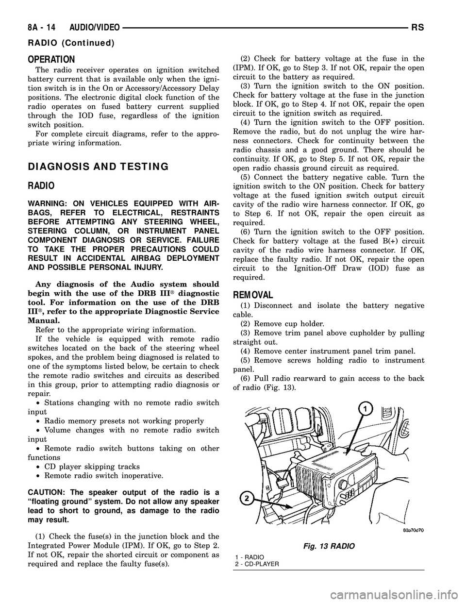
of radio (Fig. 13).
Fig. 13 RADIO
1 - RADIO
2 - CD-PLAYER
8A - 14 AUDIO/VIDEORS
RADIO (Continued)
Page 274 of 2339
CAUTION: Pulling the antenna cable straight out of
the radio without pulling on the locking antenna
connector could damage the cable or radio.
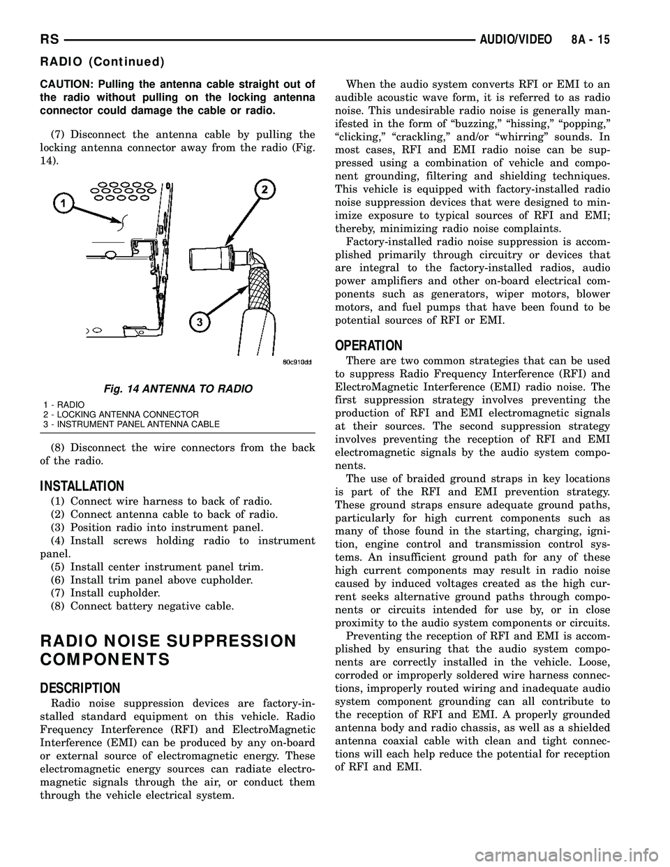
(7) Disconnect the antenna cable by pulling the
locking antenna connector away from the radio (Fig.
14).
(8) Disconnect the wire connectors from the back
of the radio.
INSTALLATION
(1) Connect wire harness to back of radio.
(2) Connect antenna cable to back of radio.
(3) Position radio into instrument panel.
(4) Install screws holding radio to instrument
panel.
(5) Install center instrument panel trim.
(6) Install trim panel above cupholder.
(7) Install cupholder.
(8) Connect battery negative cable.
RADIO NOISE SUPPRESSION
COMPONENTS
DESCRIPTION
Radio noise suppression devices are factory-in-
stalled standard equipment on this vehicle. Radio
Frequency Interference (RFI) and ElectroMagnetic
Interference (EMI) can be produced by any on-board
or external source of electromagnetic energy. These
electromagnetic energy sources can radiate electro-
magnetic signals through the air, or conduct them
through the vehicle electrical system.When the audio system converts RFI or EMI to an
audible acoustic wave form, it is referred to as radio
noise. This undesirable radio noise is generally man-
ifested in the form of ªbuzzing,º ªhissing,º ªpopping,º
ªclicking,º ªcrackling,º and/or ªwhirringº sounds. In
most cases, RFI and EMI radio noise can be sup-
pressed using a combination of vehicle and compo-
nent grounding, filtering and shielding techniques.
This vehicle is equipped with factory-installed radio
noise suppression devices that were designed to min-
imize exposure to typical sources of RFI and EMI;
thereby, minimizing radio noise complaints.
Factory-installed radio noise suppression is accom-
plished primarily through circuitry or devices that
are integral to the factory-installed radios, audio
power amplifiers and other on-board electrical com-
ponents such as generators, wiper motors, blower
motors, and fuel pumps that have been found to be
potential sources of RFI or EMI.
OPERATION
There are two common strategies that can be used
to suppress Radio Frequency Interference (RFI) and
ElectroMagnetic Interference (EMI) radio noise. The
first suppression strategy involves preventing the
production of RFI and EMI electromagnetic signals
at their sources. The second suppression strategy
involves preventing the reception of RFI and EMI
electromagnetic signals by the audio system compo-
nents.
The use of braided ground straps in key locations
is part of the RFI and EMI prevention strategy.
These ground straps ensure adequate ground paths,
particularly for high current components such as
many of those found in the starting, charging, igni-
tion, engine control and transmission control sys-
tems. An insufficient ground path for any of these
high current components may result in radio noise
caused by induced voltages created as the high cur-
rent seeks alternative ground paths through compo-
nents or circuits intended for use by, or in close
proximity to the audio system components or circuits.
Preventing the reception of RFI and EMI is accom-
plished by ensuring that the audio system compo-
nents are correctly installed in the vehicle. Loose,
corroded or improperly soldered wire harness connec-
tions, improperly routed wiring and inadequate audio
system component grounding can all contribute to
the reception of RFI and EMI. A properly grounded
antenna body and radio chassis, as well as a shielded
antenna coaxial cable with clean and tight connec-
tions will each help reduce the potential for reception
of RFI and EMI.
Fig. 14 ANTENNA TO RADIO
1 - RADIO
2 - LOCKING ANTENNA CONNECTOR
3 - INSTRUMENT PANEL ANTENNA CABLE
RSAUDIO/VIDEO8A-15
RADIO (Continued)
Page 292 of 2339
FRONT CONTROL MODULE
DESCRIPTION
The Front Control Module (FCM) is a micro con-
troller based module located in the engine compart-
ment. The FCM mates to the Power Distribution
Center (PDC) to form the Integrated Power Module
(IPM). The IPM connects directly to the battery and
provides the primary means of circuit protection and
power distribution for all vehicle electrical systems.
The FCM controls power to some of these vehicle sys-
tems electrical and electromechanical loads based on
inputs received from hard wired switch inputs and
data received on the Programmable Communications
Interface (PCI) data bus.
For information on the IPM, (Refer to 8 - ELEC-
TRICAL/POWER DISTRIBUTION/INTEGRATED
POWER MODULE - DESCRIPTION)
OPERATION
As messages are sent over the Programmable Com-
munications Interface (PCI) data bus, the Front Con-
trol Module (FCM) reads these messages and controls
power to some of the vehicles electrical systems by
completing the circuit to ground (low side driver) or
completing the circuit to 12 volt power (high side
driver).
The following functions arecontrolledby the
Front Control Module:
²Accessory Relay Actuation
²Brake Transmission Shift Interlock Functions
(BTSI - gas engine only)
²Diesel Cabin Heater (Diesel Engine Vehicles)
²Electronic Back Light (EBL) Rear Defogger
²Front and Rear Blower Motor Relay Actuation
²Front Fog Lamp Relay Actuation
²Washer Motor (front and rear)
²Front Windshield Wiper ªHIº & ªLOº Relay
Actuation
²Front Windshield Wiper ªONº Relay Actuation
²Headlamp Power with Voltage Regulation
²Horn Relay Actuation
²Headlamp Washer Relay Actuation (IF
EQUIPPED - EXPORT ONLY)
²Name Brand Speaker (NBS) Relay Actuation
²Park Lamp Relay Actuation
The following inputs areReceived/Monitoredby
the Front Control Module:
²Ambient Temperature Sensing
²Back-Up switch
²Brake Fluid Level
²B+ Connection Detection
²Engine Crank Signal (Diesel Engine Vehicles)
²Horn Input
²Ignition Switch Start Only
²Ignition Switch Run and Start Only²Stop Lamp Sense
²Washer Fluid Level
²Windshield Wiper Park
DIAGNOSIS AND TESTING
FRONT CONTROL MODULE
The Front Control Module (FCM) is a printed cir-
cuit board based module with a on-board micro-pro-
cessor. The FCM interfaces with other electronic
modules in the vehicle via the Programmable Com-
munications Interface (PCI) data bus. In order to
obtain conclusive testing the PCI data bus and all of
the electronic modules that provide inputs to, or
receive outputs from the FCM must be checked. All
PCI communication faults must be resolved prior to
further diagnosing any front control module related
issues.
The FCM was designed to be diagnosed with an
appropriate diagnostic scan tool, such as the DRB
IIIt. The most reliable, efficient, and accurate means
to diagnose the front control module requires the use
of a DRB IIItscan tool and the proper Body Diag-
nostic Procedures manual.
Before any testing of the FCM is attempted, the
battery should be fully charged and all wire harness
and ground connections inspected around the affected
areas on the vehicle.
REMOVAL
(1) Disconnect and isolate the negative and posi-
tive battery cables from the battery.
(2) Remove the battery (Refer to 8 - ELECTRI-
CAL/BATTERY SYSTEM/BATTERY - REMOVAL).
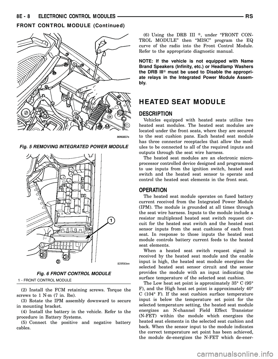
(3) Using a long flat-bladed screwdriver, gently
twist the Integrated Power Module (IPM) retaining
clip outboard to free the IPM from its mounting
bracket (Fig. 5). Rotate IPM upward to access the
Front Control Module (FCM) retaining screws.
(4) Remove the front control module retaining
screws.
(5) Pull the FCM straight from the IPM assembly
to disconnect the electrical connector (Fig. 6) and
remove the FCM from the vehicle.
INSTALLATION
NOTE: Front Control Module must be programmed
to the correct radio EQ curve using the DRB IIIT.
This will ensure that the audio system is operating
correctly.
(1) Install the Front Control Module (FCM) in the
Integrated Power Module (IPM) assembly by pushing
the 49-way electrical connector straight in.
RSELECTRONIC CONTROL MODULES8E-7
Page 293 of 2339
(2) Install the FCM retaining screws. Torque the
screws to 1 N´m (7 in. lbs).
(3) Rotate the IPM assembly downward to secure
in mounting bracket.
(4) Install the battery in the vehicle. Refer to the
procedure in Battery Systems.
(5) Connect the positive and negative battery
cables.(6) Using the DRB IIIt, under ªFRONT CON-
TROL MODULEº then ªMISCº program the EQ
curve of the radio into the Front Control Module.
Refer to the appropriate diagnostic manual.
NOTE: If the vehicle is not equipped with Name
Brand Speakers (Infinity, etc.) or Headlamp Washers
the DRB IIITmust be used to Disable the appropri-
ate relays in the Integrated Power Module Assem-
bly.
HEATED SEAT MODULE
DESCRIPTION
Vehicles equipped with heated seats utilize two
heated seat modules. The heated seat modules are
located under the front seats, where they are secured
to the seat cushion pans. Each heated seat module
has three connector receptacles that allow the mod-
ules to be connected to all of the required inputs and
outputs through the seat wire harness.
The heated seat modules are an electronic micro-
processor controlled device designed and programmed
to use inputs from the ignition switch, heated seat
switch and the heated seat sensor to operate and
control the heated seat elements in the front seat.
OPERATION
The heated seat module operates on fused battery
current received from the Integrated Power Module
(IPM). The module is grounded at all times through
the seat wire harness. Inputs to the module include a
resistor multiplexed heated seat switch request cir-
cuit for the heated seat switch and the heated seat
sensor inputs from the seat cushions of each front
seat. In response to those inputs the heated seat
module controls battery current feeds to the heated
seat elements.
When a heated seat switch request signal is
received by the heated seat module and the enable
input is high, the heated seat module energizes the
selected heated seat sensor circuit and the sensor
provides the module with an input indicating the
surface temperature of the selected seat cushion.
The Low heat set point is approximately 35É C (95É
F), and the High heat set point is approximately 40É
C (104É F). If the seat cushion surface temperature
input is below the temperature set point for the
selected temperature setting, the heated seat module
energizes an N-channel Field Effect Transistor
(N-FET) within the module which energizes the
heated seat elements in the selected seat cushion and
back. When the sensor input to the module indicates
the correct temperature set point has been achieved,
the module de-energizes the N-FET which de-ener-
Fig. 5 REMOVING INTEGRATED POWER MODULE
Fig. 6 FRONT CONTROL MODULE
1 - FRONT CONTROL MODULE
8E - 8 ELECTRONIC CONTROL MODULESRS
FRONT CONTROL MODULE (Continued)
Page 309 of 2339
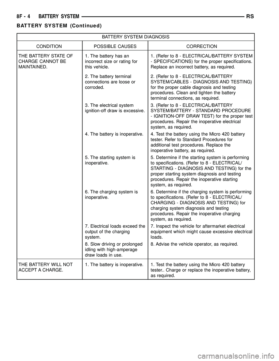
BATTERY SYSTEM DIAGNOSIS
CONDITION POSSIBLE CAUSES CORRECTION
THE BATTERY STATE OF
CHARGE CANNOT BE
MAINTAINED.1. The battery has an
incorrect size or rating for
this vehicle.1. (Refer to 8 - ELECTRICAL/BATTERY SYSTEM
- SPECIFICATIONS) for the proper specifications.
Replace an incorrect battery, as required.
2. The battery terminal
connections are loose or
corroded.2. (Refer to 8 - ELECTRICAL/BATTERY
SYSTEM/CABLES - DIAGNOSIS AND TESTING)
for the proper cable diagnosis and testing
procedures. Clean and tighten the battery
terminal connections, as required.
3. The electrical system
ignition-off draw is excessive.3. (Refer to 8 - ELECTRICAL/BATTERY
SYSTEM/BATTERY - STANDARD PROCEDURE
- IGNITION-OFF DRAW TEST) for the proper test
procedures. Repair the inoperative electrical
system, as required.
4. The battery is inoperative. 4. Test the battery using the Micro 420 battery
tester. Refer to Standard Procedures for
additional test procedures. Replace the
inoperative battery, as required.
5. The starting system is
inoperative.5. Determine if the starting system is performing
to specifications. (Refer to 8 - ELECTRICAL/
STARTING - DIAGNOSIS AND TESTING) for the
proper starting system diagnosis and testing
procedures. Repair the inoperative starting
system, as required.
6. The charging system is
inoperative.6. Determine if the charging system is performing
to specifications. (Refer to 8 - ELECTRICAL/
CHARGING - DIAGNOSIS AND TESTING) for
charging system diagnosis and testing
procedures. Repair the inoperative charging
system, as required.
7. Electrical loads exceed the
output of the charging
system.7. Inspect the vehicle for aftermarket electrical
equipment which might cause excessive electrical
loads.
8. Slow driving or prolonged
idling with high-amperage
draw loads in use.8. Advise the vehicle operator, as required.
THE BATTERY WILL NOT
ACCEPT A CHARGE.1. The battery is inoperative. 1. Test the battery using the Micro 420 battery
tester.. Charge or replace the inoperative battery,
as required.
8F - 4 BATTERY SYSTEMRS
BATTERY SYSTEM (Continued)