clock CHRYSLER VOYAGER 2005 Manual PDF
[x] Cancel search | Manufacturer: CHRYSLER, Model Year: 2005, Model line: VOYAGER, Model: CHRYSLER VOYAGER 2005Pages: 2339, PDF Size: 59.69 MB
Page 1337 of 2339
INSTALLATION
INSTALLATION - CRANKSHAFT SPROCKET
(1) Position the sprocket on the crankshaft (timing
mark out) with the timing slot aligned with the tim-
ing pin.
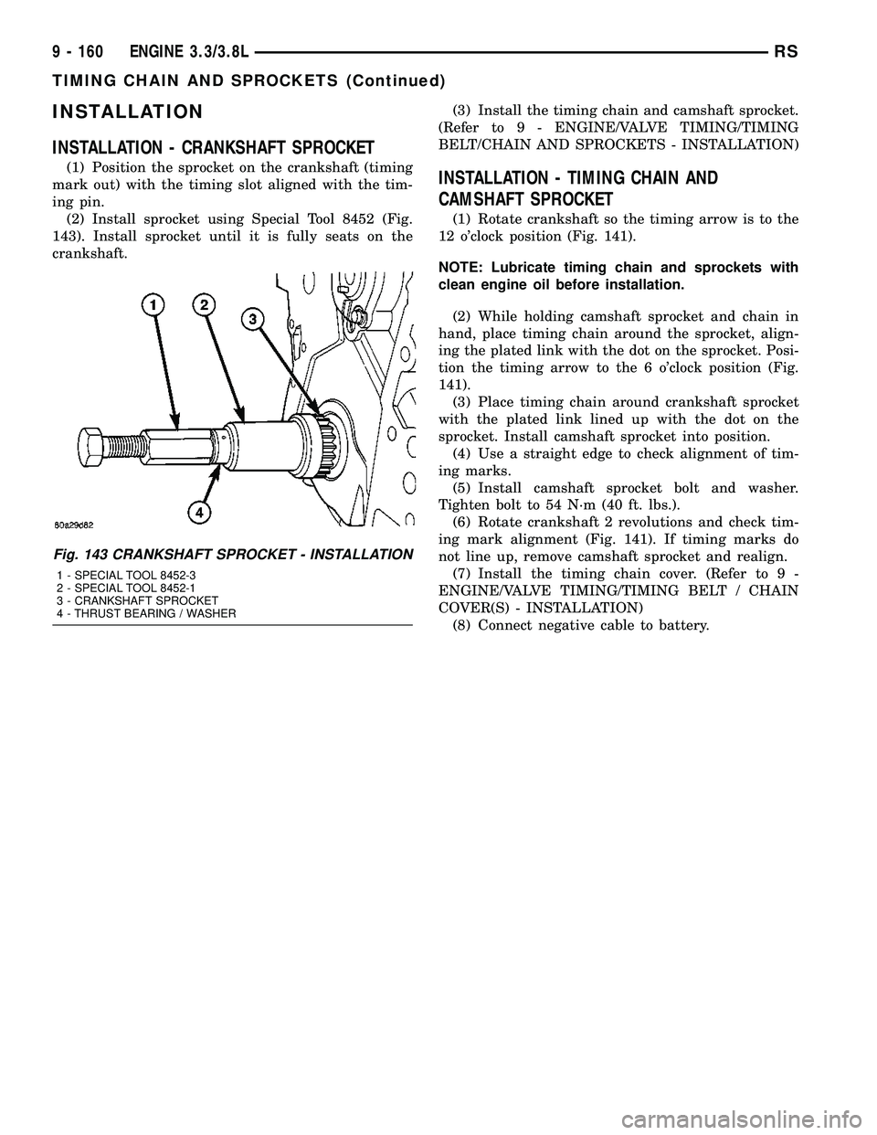
(2) Install sprocket using Special Tool 8452 (Fig.
143). Install sprocket until it is fully seats on the
crankshaft.(3) Install the timing chain and camshaft sprocket.
(Refer to 9 - ENGINE/VALVE TIMING/TIMING
BELT/CHAIN AND SPROCKETS - INSTALLATION)INSTALLATION - TIMING CHAIN AND
CAMSHAFT SPROCKET
(1) Rotate crankshaft so the timing arrow is to the
12 o'clock position (Fig. 141).
NOTE: Lubricate timing chain and sprockets with
clean engine oil before installation.
(2) While holding camshaft sprocket and chain in
hand, place timing chain around the sprocket, align-
ing the plated link with the dot on the sprocket. Posi-
tion the timing arrow to the 6 o'clock position (Fig.
141).
(3) Place timing chain around crankshaft sprocket
with the plated link lined up with the dot on the
sprocket. Install camshaft sprocket into position.
(4) Use a straight edge to check alignment of tim-
ing marks.
(5) Install camshaft sprocket bolt and washer.
Tighten bolt to 54 N´m (40 ft. lbs.).
(6) Rotate crankshaft 2 revolutions and check tim-
ing mark alignment (Fig. 141). If timing marks do
not line up, remove camshaft sprocket and realign.
(7) Install the timing chain cover. (Refer to 9 -
ENGINE/VALVE TIMING/TIMING BELT / CHAIN
COVER(S) - INSTALLATION)
(8) Connect negative cable to battery.
Fig. 143 CRANKSHAFT SPROCKET - INSTALLATION
1 - SPECIAL TOOL 8452-3
2 - SPECIAL TOOL 8452-1
3 - CRANKSHAFT SPROCKET
4 - THRUST BEARING / WASHER
9 - 160 ENGINE 3.3/3.8LRS
TIMING CHAIN AND SPROCKETS (Continued)
Page 1362 of 2339
REMOVAL
The front cradle crossmember must be installed in
the design location to achieve proper front end sus-
pension alignment. If the cradle crossmember is
removed without applying reference marks on the
frame rails, align the cradle crossmember according
to the dimensions provided in this group.
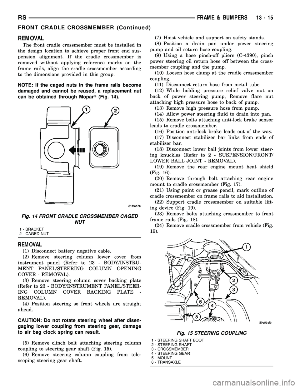
NOTE: If the caged nuts in the frame rails become
damaged and cannot be reused, a replacement nut
can be obtained through MoparT(Fig. 14).
REMOVAL
(1) Disconnect battery negative cable.
(2) Remove steering column lower cover from
instrument panel (Refer to 23 - BODY/INSTRU-
MENT PANEL/STEERING COLUMN OPENING
COVER - REMOVAL).
(3) Remove steering column cover backing plate
(Refer to 23 - BODY/INSTRUMENT PANEL/STEER-
ING COLUMN COVER BACKING PLATE -
REMOVAL).
(4) Position steering so front wheels are straight
ahead.
CAUTION: Do not rotate steering wheel after disen-
gaging lower coupling from steering gear, damage
to air bag clock spring can result.
(5) Remove clinch bolt attaching steering column
coupling to steering gear shaft (Fig. 15).
(6) Remove steering column coupling from tele-
scoping steering gear shaft.(7) Hoist vehicle and support on safety stands.
(8) Position a drain pan under power steering
pump and oil return hose coupling.
(9) Using a hose pinch-off pliers (C-4390), pinch
power steering oil return hose off between the cross-
member coupling and the pump.
(10) Loosen hose clamp at the cradle crossmember
coupling.
(11) Disconnect return hose from metal tube.
(12) While holding pressure relief valve nut on
back of power steering pump, Remove flare nut
attaching high pressure hose to back of pump.
(13) Remove high pressure hose from pump.
(14) Allow power steering fluid to drain into pan.
(15) Remove bolts attaching anti-lock brake sensor
leads to cradle crossmember.
(16) Position anti-lock brake leads out of the way.
(17) Disconnect stabilizer bar links from ends of
stabilizer bar.
(18) Disconnect lower ball joints from lower steer-
ing knuckles (Refer to 2 - SUSPENSION/FRONT/
LOWER BALL JOINT - REMOVAL).
(19) Remove the rear engine mount heat shield
(Fig. 16).
(20) Remove through bolt attaching rear engine
mount to cradle crossmember (Fig. 17).
(21) Using paint or grease pencil, mark outline of
cradle crossmember on frame rails to aid installation.
(22) Support cradle crossmember on suitable lift-
ing device (Fig. 19).
(23) Remove bolts attaching crossmember to front
frame rails (Fig. 18).
(24) Remove cradle crossmember from vehicle (Fig.
19).
Fig. 14 FRONT CRADLE CROSSMEMBER CAGED
NUT
1 - BRACKET
2 - CAGED NUT
Fig. 15 STEERING COUPLING
1 - STEERING SHAFT BOOT
2 - STEERING SHAFT
3 - CROSSMEMBER
4 - STEERING GEAR
5 - MOUNT
6 - TRANSAXLE
RSFRAME & BUMPERS13-15
FRONT CRADLE CROSSMEMBER (Continued)
Page 1412 of 2339
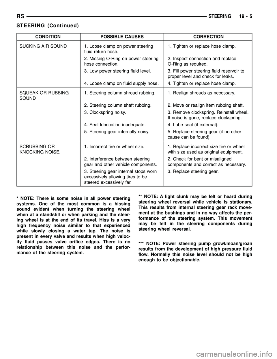
CONDITION POSSIBLE CAUSES CORRECTION
SUCKING AIR SOUND 1. Loose clamp on power steering
fluid return hose.1. Tighten or replace hose clamp.
2. Missing O-Ring on power steering
hose connection.2. Inspect connection and replace
O-Ring as required.
3. Low power steering fluid level. 3. Fill power steering fluid reservoir to
proper level and check for leaks.
4. Loose clamp on fluid supply hose. 4. Tighten or replace hose clamp.
SQUEAK OR RUBBING
SOUND1. Steering column shroud rubbing. 1. Realign shrouds as necessary.
2. Steering column shaft rubbing. 2. Move or realign item rubbing shaft.
3. Clockspring noisy. 3. Remove clockspring. Reinstall wheel.
If noise is gone, replace clockspring.
4. Seal lubrication inadequate. 4. Lube seal (if external).
5. Steering gear internally noisy. 5. Replace steering gear (if no other
cause can be found).
SCRUBBING OR
KNOCKING NOISE.1. Incorrect tire or wheel size. 1. Replace incorrect size tire or wheel
with size used as original equipment.
2. Interference between steering
gear and other vehicle components.2. Check for bent or misaligned
components and correct as necessary.
3. Steering gear internal stops worn
excessively allowing tires to be
steered excessively far.3. Replace steering gear.
* NOTE: There is some noise in all power steering
systems. One of the most common is a hissing
sound evident when turning the steering wheel
when at a standstill or when parking and the steer-
ing wheel is at the end of its travel. Hiss is a very
high frequency noise similar to that experienced
while slowly closing a water tap. The noise is
present in every valve and results when high veloc-
ity fluid passes valve orifice edges. There is no
relationship between this noise and the perfor-
mance of the steering system.** NOTE: A light clunk may be felt or heard during
steering wheel reversal while vehicle is stationary.
This results from internal steering gear rack move-
ment at the bushings and in no way affects the per-
formance of the steering system. This movement
may be felt in the steering components during
steering wheel reversal.
*** NOTE: Power steering pump growl/moan/groan
results from the development of high pressure fluid
flow. Normally this noise level should not be high
enough to be objectionable.
RSSTEERING19-5
STEERING (Continued)
Page 1415 of 2339
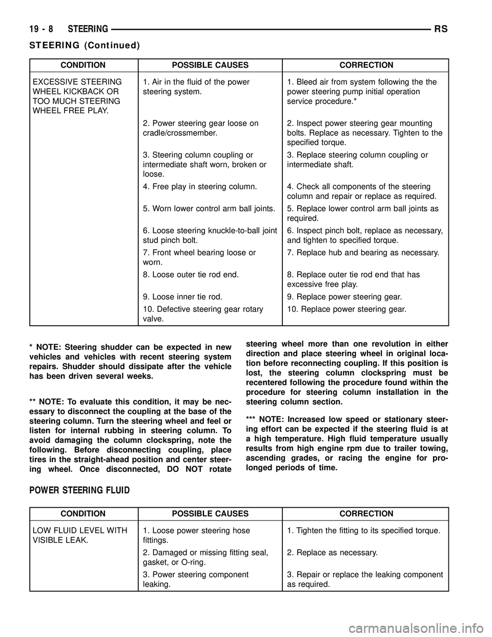
CONDITION POSSIBLE CAUSES CORRECTION
EXCESSIVE STEERING
WHEEL KICKBACK OR
TOO MUCH STEERING
WHEEL FREE PLAY.1. Air in the fluid of the power
steering system.1. Bleed air from system following the the
power steering pump initial operation
service procedure.*
2. Power steering gear loose on
cradle/crossmember.2. Inspect power steering gear mounting
bolts. Replace as necessary. Tighten to the
specified torque.
3. Steering column coupling or
intermediate shaft worn, broken or
loose.3. Replace steering column coupling or
intermediate shaft.
4. Free play in steering column. 4. Check all components of the steering
column and repair or replace as required.
5. Worn lower control arm ball joints. 5. Replace lower control arm ball joints as
required.
6. Loose steering knuckle-to-ball joint
stud pinch bolt.6. Inspect pinch bolt, replace as necessary,
and tighten to specified torque.
7. Front wheel bearing loose or
worn.7. Replace hub and bearing as necessary.
8. Loose outer tie rod end. 8. Replace outer tie rod end that has
excessive free play.
9. Loose inner tie rod. 9. Replace power steering gear.
10. Defective steering gear rotary
valve.10. Replace power steering gear.
* NOTE: Steering shudder can be expected in new
vehicles and vehicles with recent steering system
repairs. Shudder should dissipate after the vehicle
has been driven several weeks.
** NOTE: To evaluate this condition, it may be nec-
essary to disconnect the coupling at the base of the
steering column. Turn the steering wheel and feel or
listen for internal rubbing in steering column. To
avoid damaging the column clockspring, note the
following. Before disconnecting coupling, place
tires in the straight-ahead position and center steer-
ing wheel. Once disconnected, DO NOT rotatesteering wheel more than one revolution in either
direction and place steering wheel in original loca-
tion before reconnecting coupling. If this position is
lost, the steering column clockspring must be
recentered following the procedure found within the
procedure for steering column installation in the
steering column section.
*** NOTE: Increased low speed or stationary steer-
ing effort can be expected if the steering fluid is at
a high temperature. High fluid temperature usually
results from high engine rpm due to trailer towing,
ascending grades, or racing the engine for pro-
longed periods of time.
POWER STEERING FLUID
CONDITION POSSIBLE CAUSES CORRECTION
LOW FLUID LEVEL WITH
VISIBLE LEAK.1. Loose power steering hose
fittings.1. Tighten the fitting to its specified torque.
2. Damaged or missing fitting seal,
gasket, or O-ring.2. Replace as necessary.
3. Power steering component
leaking.3. Repair or replace the leaking component
as required.
19 - 8 STEERINGRS
STEERING (Continued)
Page 1417 of 2339
COLUMN
TABLE OF CONTENTS
page page
COLUMN
DESCRIPTION - STEERING COLUMN.......10
WARNING
WARNINGS AND CAUTIONS.............10
DIAGNOSIS AND TESTING - STEERING
COLUMN............................11
REMOVAL.............................11
INSTALLATION.........................16
SPECIFICATIONS
COLUMN FASTENER TORQUE...........17
IGNITION SWITCH
REMOVAL.............................17
INSTALLATION.........................19
KEY/LOCK CYLINDER
DESCRIPTION.........................20OPERATION...........................20
REMOVAL.............................20
INSTALLATION.........................20
SHROUD - LOWER
REMOVAL.............................21
INSTALLATION.........................21
SHROUD - UPPER
REMOVAL.............................22
INSTALLATION.........................22
STEERING WHEEL
REMOVAL.............................23
INSTALLATION.........................24
COLUMN
DESCRIPTION - STEERING COLUMN
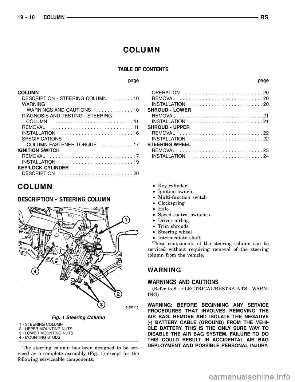
The steering column has been designed to be ser-
viced as a complete assembly (Fig. 1) except for the
following serviceable components:²Key cylinder
²Ignition switch
²Multi-function switch
²Clockspring
²Halo
²Speed control switches
²Driver airbag
²Trim shrouds
²Steering wheel
²Intermediate shaft
These components of the steering column can be
serviced without requiring removal of the steering
column from the vehicle.
WARNING
WARNINGS AND CAUTIONS
(Refer to 8 - ELECTRICAL/RESTRAINTS - WARN-
ING)
WARNING: BEFORE BEGINNING ANY SERVICE
PROCEDURES THAT INVOLVES REMOVING THE
AIR BAG. REMOVE AND ISOLATE THE NEGATIVE
(-) BATTERY CABLE (GROUND) FROM THE VEHI-
CLE BATTERY. THIS IS THE ONLY SURE WAY TO
DISABLE THE AIR BAG SYSTEM. FAILURE TO DO
THIS COULD RESULT IN ACCIDENTAL AIR BAG
DEPLOYMENT AND POSSIBLE PERSONAL INJURY.
Fig. 1 Steering Column
1 - STEERING COLUMN
2 - UPPER MOUNTING NUTS
3 - LOWER MOUNTING NUTS
4 - MOUNTING STUDS
19 - 10 COLUMNRS
Page 1418 of 2339
WARNING: THE AIR BAG SYSTEM IS A SENSITIVE,
COMPLEX ELECTRO-MECHANICAL UNIT. BEFORE
ATTEMPTING TO DIAGNOSE, REMOVE OR INSTALL
THE AIR BAG SYSTEM COMPONENTS YOU MUST
FIRST DISCONNECT AND ISOLATE THE BATTERY
NEGATIVE (GROUND) CABLE. THEN WAIT TWO
MINUTES FOR THE SYSTEM CAPACITOR TO DIS-
CHARGE. FAILURE TO DO SO COULD RESULT IN
ACCIDENTAL DEPLOYMENT OF THE AIR BAG AND
POSSIBLE PERSONAL INJURY. THE FASTENERS,
SCREWS, AND BOLTS, ORIGINALLY USED FOR
THE AIR BAG COMPONENTS, HAVE SPECIAL
COATINGS AND ARE SPECIFICALLY DESIGNED
FOR THE AIR BAG SYSTEM. THEY MUST NEVER
BE REPLACED WITH ANY SUBSTITUTES. ANYTIME
A NEW FASTENER IS NEEDED, REPLACE WITH
THE CORRECT FASTENERS PROVIDED IN THE
SERVICE PACKAGE OR FASTENERS LISTED IN
THE PARTS BOOKS.
WARNING: SAFETY GOGGLES SHOULD BE WORN
AT ALL TIMES WHEN WORKING ON STEERING
COLUMNS.
CAUTION: Disconnect negative (ground) cable from
the battery before servicing any column compo-
nent.
CAUTION: Do not attempt to remove the pivot pins
to disassemble the tilting mechanism. Damage will
occur.
DIAGNOSIS AND TESTING - STEERING
COLUMN
For diagnosis of conditions relating to the steering
column, (Refer to 19 - STEERING - DIAGNOSIS
AND TESTING).
REMOVAL
NOTE: Before proceeding, (Refer to 19 - STEERING/
COLUMN - WARNING)(Refer to 8 - ELECTRICAL/RE-
STRAINTS/DRIVER AIRBAG - REMOVAL).
(1) Make sure the front wheels of the vehicle are
in the STRAIGHT AHEAD position before beginning
the column removal procedure.
(2) Disconnect and isolate the negative (ground)
cable from the battery. Wait at least two minutes for
the airbag system reserve capacitor to discharge
before beginning any steering column, instrument
panel, or airbag system/component service.WARNING: WHEN AN UNDEPLOYED AIRBAG IS TO
BE REMOVED FROM THE VEHICLE, FIRST DISCON-
NECT AND ISOLATE THE BATTERY NEGATIVE
(GROUND) CABLE. ALLOW THE AIRBAG SYSTEM
RESERVE CAPACITOR TO DISCHARGE FOR TWO
MINUTES BEFORE BEGINNING ANY AIRBAG SYS-
TEM OR COMPONENT SERVICE. PERSONAL
INJURY MAY RESULT IF THIS PROCEDURE IS NOT
FOLLOWED.
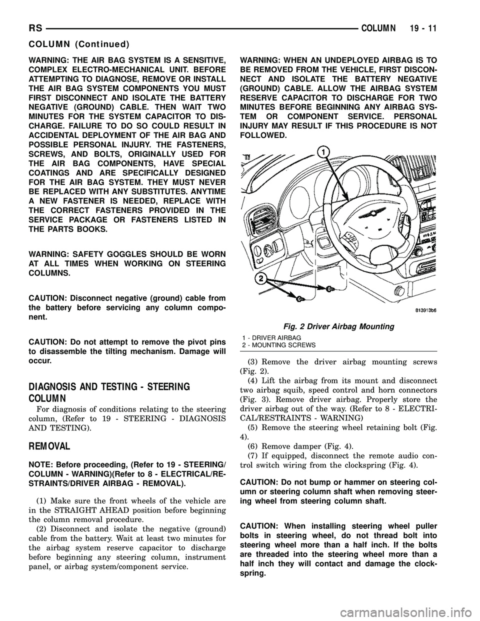
(3) Remove the driver airbag mounting screws
(Fig. 2).
(4) Lift the airbag from its mount and disconnect
two airbag squib, speed control and horn connectors
(Fig. 3). Remove driver airbag. Properly store the
driver airbag out of the way. (Refer to 8 - ELECTRI-
CAL/RESTRAINTS - WARNING)
(5) Remove the steering wheel retaining bolt (Fig.
4).
(6) Remove damper (Fig. 4).
(7) If equipped, disconnect the remote audio con-
trol switch wiring from the clockspring (Fig. 4).
CAUTION: Do not bump or hammer on steering col-
umn or steering column shaft when removing steer-
ing wheel from steering column shaft.
CAUTION: When installing steering wheel puller
bolts in steering wheel, do not thread bolt into
steering wheel more than a half inch. If the bolts
are threaded into the steering wheel more than a
half inch they will contact and damage the clock-
spring.
Fig. 2 Driver Airbag Mounting
1 - DRIVER AIRBAG
2 - MOUNTING SCREWS
RSCOLUMN19-11
COLUMN (Continued)
Page 1419 of 2339
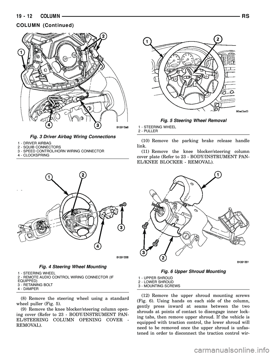
(8) Remove the steering wheel using a standard
wheel puller (Fig. 5).
(9) Remove the knee blocker/steering column open-
ing cover (Refer to 23 - BODY/INSTRUMENT PAN-
EL/STEERING COLUMN OPENING COVER -
REMOVAL).(10) Remove the parking brake release handle
link.
(11) Remove the knee blocker/steering column
cover plate (Refer to 23 - BODY/INSTRUMENT PAN-
EL/KNEE BLOCKER - REMOVAL).
(12) Remove the upper shroud mounting screws
(Fig. 6). Using hands on each side of the column,
gently press inward at seams between the two
shrouds at points of contact to disengage inner lock-
ing tabs, then remove upper shroud. If the vehicle is
equipped with traction control, the lower shroud will
need to be removed once the upper shroud is unfas-
tened in order to disconnect the traction control wir-
Fig. 3 Driver Airbag Wiring Connections
1 - DRIVER AIRBAG
2 - SQUIB CONNECTORS
3 - SPEED CONTROL/HORN WIRING CONNECTOR
4 - CLOCKSPRING
Fig. 4 Steering Wheel Mounting
1 - STEERING WHEEL
2 - REMOTE AUDIO CONTROL WIRING CONNECTOR (IF
EQUIPPED)
3 - RETAINING BOLT
4 - DAMPER
Fig. 5 Steering Wheel Removal
1 - STEERING WHEEL
2 - PULLER
Fig. 6 Upper Shroud Mounting
1 - UPPER SHROUD
2 - LOWER SHROUD
3 - MOUNTING SCREWS
19 - 12 COLUMNRS
COLUMN (Continued)
Page 1421 of 2339
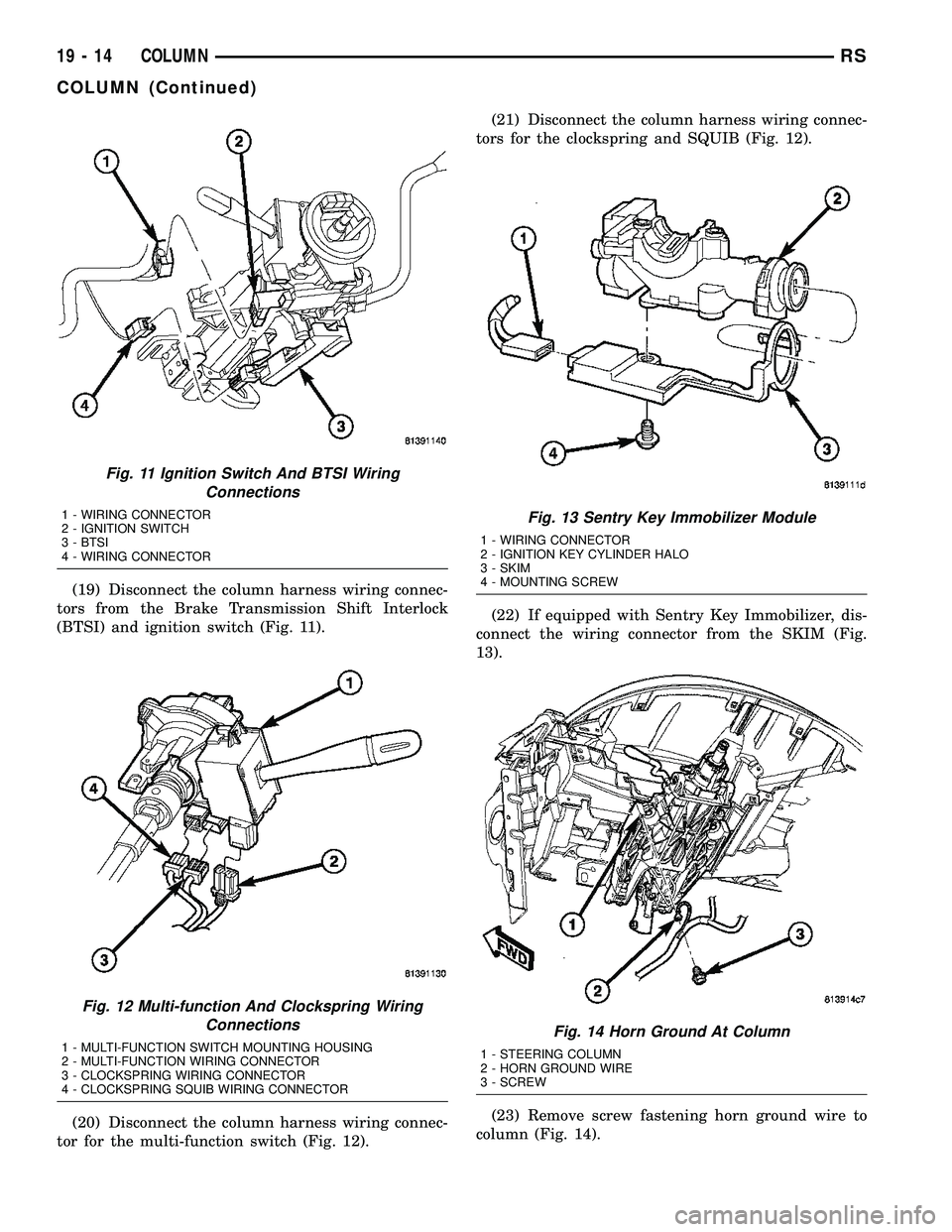
(19) Disconnect the column harness wiring connec-
tors from the Brake Transmission Shift Interlock
(BTSI) and ignition switch (Fig. 11).
(20) Disconnect the column harness wiring connec-
tor for the multi-function switch (Fig. 12).(21) Disconnect the column harness wiring connec-
tors for the clockspring and SQUIB (Fig. 12).
(22) If equipped with Sentry Key Immobilizer, dis-
connect the wiring connector from the SKIM (Fig.
13).
(23) Remove screw fastening horn ground wire to
column (Fig. 14).
Fig. 11 Ignition Switch And BTSI Wiring
Connections
1 - WIRING CONNECTOR
2 - IGNITION SWITCH
3 - BTSI
4 - WIRING CONNECTOR
Fig. 12 Multi-function And Clockspring Wiring
Connections
1 - MULTI-FUNCTION SWITCH MOUNTING HOUSING
2 - MULTI-FUNCTION WIRING CONNECTOR
3 - CLOCKSPRING WIRING CONNECTOR
4 - CLOCKSPRING SQUIB WIRING CONNECTOR
Fig. 13 Sentry Key Immobilizer Module
1 - WIRING CONNECTOR
2 - IGNITION KEY CYLINDER HALO
3 - SKIM
4 - MOUNTING SCREW
Fig. 14 Horn Ground At Column
1 - STEERING COLUMN
2 - HORN GROUND WIRE
3 - SCREW
19 - 14 COLUMNRS
COLUMN (Continued)
Page 1423 of 2339
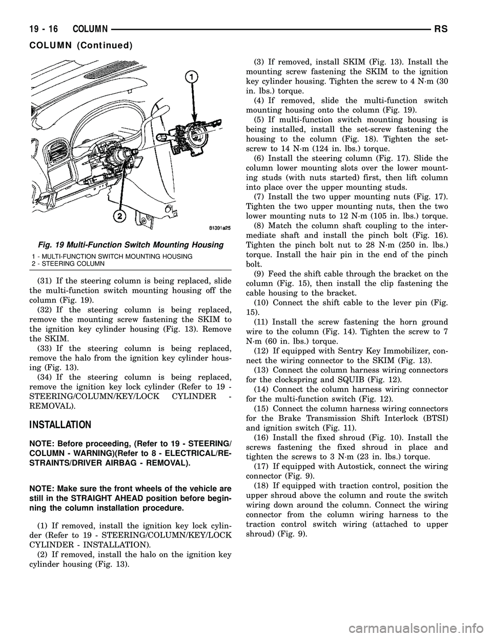
(31) If the steering column is being replaced, slide
the multi-function switch mounting housing off the
column (Fig. 19).
(32) If the steering column is being replaced,
remove the mounting screw fastening the SKIM to
the ignition key cylinder housing (Fig. 13). Remove
the SKIM.
(33) If the steering column is being replaced,
remove the halo from the ignition key cylinder hous-
ing (Fig. 13).
(34) If the steering column is being replaced,
remove the ignition key lock cylinder (Refer to 19 -
STEERING/COLUMN/KEY/LOCK CYLINDER -
REMOVAL).
INSTALLATION
NOTE: Before proceeding, (Refer to 19 - STEERING/
COLUMN - WARNING)(Refer to 8 - ELECTRICAL/RE-
STRAINTS/DRIVER AIRBAG - REMOVAL).
NOTE: Make sure the front wheels of the vehicle are
still in the STRAIGHT AHEAD position before begin-
ning the column installation procedure.
(1) If removed, install the ignition key lock cylin-
der (Refer to 19 - STEERING/COLUMN/KEY/LOCK
CYLINDER - INSTALLATION).
(2) If removed, install the halo on the ignition key
cylinder housing (Fig. 13).(3) If removed, install SKIM (Fig. 13). Install the
mounting screw fastening the SKIM to the ignition
key cylinder housing. Tighten the screw to 4 N´m (30
in. lbs.) torque.
(4) If removed, slide the multi-function switch
mounting housing onto the column (Fig. 19).
(5) If multi-function switch mounting housing is
being installed, install the set-screw fastening the
housing to the column (Fig. 18). Tighten the set-
screw to 14 N´m (124 in. lbs.) torque.
(6) Install the steering column (Fig. 17). Slide the
column lower mounting slots over the lower mount-
ing studs (with nuts started) first, then lift column
into place over the upper mounting studs.
(7) Install the two upper mounting nuts (Fig. 17).
Tighten the two upper mounting nuts, then the two
lower mounting nuts to 12 N´m (105 in. lbs.) torque.
(8) Match the column shaft coupling to the inter-
mediate shaft and install the pinch bolt (Fig. 16).
Tighten the pinch bolt nut to 28 N´m (250 in. lbs.)
torque. Install the hair pin in the end of the pinch
bolt.
(9) Feed the shift cable through the bracket on the
column (Fig. 15), then install the clip fastening the
cable housing to the bracket.
(10) Connect the shift cable to the lever pin (Fig.
15).
(11) Install the screw fastening the horn ground
wire to the column (Fig. 14). Tighten the screw to 7
N´m (60 in. lbs.) torque.
(12) If equipped with Sentry Key Immobilizer, con-
nect the wiring connector to the SKIM (Fig. 13).
(13) Connect the column harness wiring connectors
for the clockspring and SQUIB (Fig. 12).
(14) Connect the column harness wiring connector
for the multi-function switch (Fig. 12).
(15) Connect the column harness wiring connectors
for the Brake Transmission Shift Interlock (BTSI)
and ignition switch (Fig. 11).
(16) Install the fixed shroud (Fig. 10). Install the
screws fastening the fixed shroud in place and
tighten the screws to 3 N´m (23 in. lbs.) torque.
(17) If equipped with Autostick, connect the wiring
connector (Fig. 9).
(18) If equipped with traction control, position the
upper shroud above the column and route the switch
wiring down around the column. Connect the wiring
connector from the column wiring harness to the
traction control switch wiring (attached to upper
shroud) (Fig. 9).
Fig. 19 Multi-Function Switch Mounting Housing
1 - MULTI-FUNCTION SWITCH MOUNTING HOUSING
2 - STEERING COLUMN
19 - 16 COLUMNRS
COLUMN (Continued)
Page 1424 of 2339
(19) Position the lower shroud on the column (Fig.
8). Install the lower shroud mounting screw. Tighten
the screw to 2 N´m (17 in. lbs.) torque.
(20) If equipped with adjustable pedals, Connect
the wiring connector for the switch (Fig. 7) to the col-
umn wiring harness.
(21) Position the upper shroud on top of the lower
shroud and snap it into place. Install the upper
shroud mounting screws (Fig. 6). Tighten the screws
to 2 N´m (17 in. lbs.) torque.
(22) Inspect shroud mating surfaces for excessive
gaps and correct as necessary.
(23) Install the cluster trim bezel (Refer to 23 -
BODY/INSTRUMENT PANEL/CLUSTER BEZEL -
INSTALLATION).
(24) Install the knee blocker/steering column cover
plate. (Refer to 23 - BODY/INSTRUMENT PANEL/
KNEE BLOCKER - INSTALLATION)
(25) Install the parking brake handle link.
(26) Install the knee blocker/steering column open-
ing cover. (Refer to 23 - BODY/INSTRUMENT PAN-
EL/STEERING COLUMN OPENING COVER -
INSTALLATION)
(27) Align the splines and install the steering
wheel on the steering column shaft(Refer to 19 -
STEERING/COLUMN/STEERING WHEEL -
INSTALLATION).
(28) Install the damper over the steering column
shaft (Fig. 4).
(29) Install the steering wheel retaining bolt (Fig.
4). Tighten the bolt to 61 N´m (45 ft. lbs.) torque.
(30) If the steering wheel is equipped with remote
audio controls, connect the wiring connector to the
clockspring (Fig. 4).
(31) Connect the two squib connectors to the
driver airbag (Fig. 3). The connectors are color coded
to avoid connector mix-up.
(32) Connect the speed control and horn connector
to the clockspring (Fig. 3).
(33) Install the airbag to the steering wheel.
Install the driver airbag mounting screws (Fig. 2).
Tighten screws to 10 N´m (90 in. lbs.) torque.
(34) Connect the battery negative (ground) cable to
battery post following special Diagnosis And Testing
procedure. (Refer to 8 - ELECTRICAL/RESTRAINTS
- DIAGNOSIS AND TESTING)
(35) Check operation of all steering column
mounted components.
(36) Road test vehicle to ensure proper operation
of steering.SPECIFICATIONS
COLUMN FASTENER TORQUE
DESCRIPTION N´mFt.
Lbs.In.
Lbs.
Driver Airbag Mounting Screws 10 Ð 90
Multi-Function Switch Mounting
Housing Set-Screw14 Ð 124
Shroud Attaching Screws - Fixed 3 Ð 23
Shroud Attaching Screws -
Lower/Upper2Ð17
SKIM Attaching Screw 4 Ð 30
Steering Column Coupling Pinch
Bolt28 Ð 250
Steering Column Mounting Nuts 12 Ð 105
Steering Wheel Retaining Bolt 61 45 Ð
IGNITION SWITCH
REMOVAL
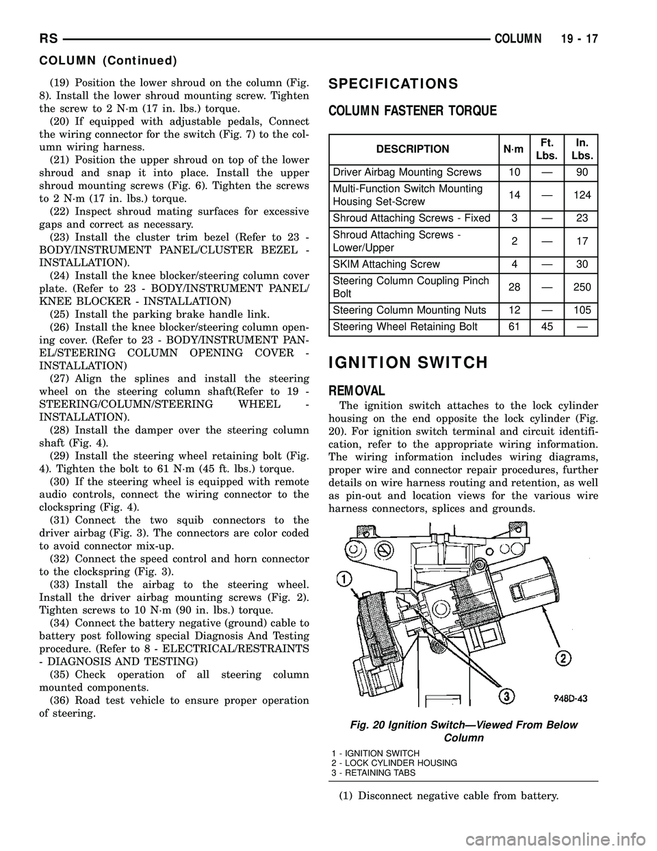
The ignition switch attaches to the lock cylinder
housing on the end opposite the lock cylinder (Fig.
20). For ignition switch terminal and circuit identifi-
cation, refer to the appropriate wiring information.
The wiring information includes wiring diagrams,
proper wire and connector repair procedures, further
details on wire harness routing and retention, as well
as pin-out and location views for the various wire
harness connectors, splices and grounds.
(1) Disconnect negative cable from battery.
Fig. 20 Ignition SwitchÐViewed From Below
Column
1 - IGNITION SWITCH
2 - LOCK CYLINDER HOUSING
3 - RETAINING TABS
RSCOLUMN19-17
COLUMN (Continued)