Rear control CHRYSLER VOYAGER 2005 Repair Manual
[x] Cancel search | Manufacturer: CHRYSLER, Model Year: 2005, Model line: VOYAGER, Model: CHRYSLER VOYAGER 2005Pages: 2339, PDF Size: 59.69 MB
Page 432 of 2339

(2) Remove the rear light bar assembly from the
vehicle. (Refer to 8 - ELECTRICAL/POWER DOORS/
SWITCH - REMOVAL) for the procedure.
(3) Grasp the light bar at its sides next to ther-
mistor/chime assembly and gently pull the two sides
of the light bar apart until the thermistor/chime
assembly can be removed.
INSTALLATION
(1) Gently pull the two sides of the light bar apart
until the thermistor/chime assembly can be installed.
(2) Install the rear light bar assembly on the vehi-
cle. (Refer to 8 - ELECTRICAL/POWER DOORS/
SWITCH - INSTALLATION) for the procedure.
(3) Connect the battery negative cable.
ENGAGE ACTUATOR
DESCRIPTION
The 12 volt engage actuator (Fig. 3) provides the
engagement and disengagement of the liftgate gear
motor to the lift gear by way of an over center link,
activated by a lever.
The engage actuator is a serviceable component
and cannot be repaired, if found to be inoperative it
must be replaced.
OPERATION
The engage actuators normal position is disen-
gaged. When a power liftgate open or close command
is generated from any of the command switches, the
power liftgate control module signals the engage
actuator to move its lever to the engaged position.
This engages the gear motor to the lift gear, so when
the motor turns the lift gate moves upward or down-
wards depending on its current position.
During a manual liftgate open or close cycle the
engage actuator is disengaged, allowing unrestricted
liftgate movement.
REMOVAL
(1) Disconnect and isolate the battery negative
cable.
(2) Remove the left rear D-pillar trim from the
vehicle, (Refer to 23 - BODY/INTERIOR/LEFT
D-PILLAR TRIM PANEL - REMOVAL).
(3) Manually engage the actuator link rod, this
must be done to access one of the engage actuator
retaining screws.
(4) Remove the two engage actuator retaining
screws (Fig. 4).
(5) Disconnect the engage actuator electrical con-
nector and remove the engage actuator from the
vehicle.
Fig. 3 LIFTGATE GEAR MOTOR ASSEMBLY
1 - TRANSVERSE BRACKET
2 - ENGAGE ACTUATOR
3 - LIFT GEAR AND ROD ASSEMBLY
4 - LIFTGATE MOTOR
Fig. 4 LIFTGATE GEAR MOTOR ASSEMBLY
1 - ENGAGE ACTUATOR RETAINING SCREWS
2 - LIFT GEAR RETAINING BOLTS
RSPOWER LIFTGATE SYSTEM8N-9
CHIME/THERMISTOR (Continued)
Page 433 of 2339
INSTALLATION
(1) Position the engage actuator in the vehicle and
connect the engage actuator electrical connector.
(2) Install the two engage actuator retaining
screws.
(3) Manually disengage the actuator.
(4) Install the left rear D-pillar trim on the vehi-
cle, (Refer to 23 - BODY/INTERIOR/LEFT D-PILLAR
TRIM PANEL - INSTALLATION).
(5) Connect the battery negative cable.
(6) Using an appropriate scan tool, check and
erase any power liftgate control module diagnostic
trouble codes.
(7) Verify power liftgate system and engage actua-
tor operation. Cycle the power liftgate through one
complete open and close cycle.
EXTERIOR HANDLE SWITCH
DESCRIPTION
The exterior handle switch is an electronic release
switch mounted to the rear license plate lamp hous-
ing assembly, located just above the license plate.
This switch controls the power liftgate release func-
tion and is also capable of reversing the power lift-
gate when it is in motion. A full power open cycle
cannot be performed using this switch, only one of
the power open command switches (key fob and over-
head console mounted) can be used to perform a full
power open cycle. The exterior handle switch is a ser-
viceable component.
OPERATION
When the exterior handle switch is depressed, with
the liftgate in the closed position, a message is sent
to the Body Control Module (BCM). The BCM then
sends a signal to the power liftgate control module
via the Programmable Communication Interface
(PCI) data bus circuit. The power liftgate control
module then sends a signal to the power latch
mounted actuator, which moves the liftgate from the
primary closed and latched position to the open and
movable position. If the liftgate is not pulled open
once the latch releases within a few seconds, the
latch will cinch closed again.
REMOVAL
(1) Disconnect and isolate the battery negative
cable.
(2) Open the liftgate and remove the liftgate trim
panel, (Refer to 23 - BODY/DECKLID/HATCH/LIFT-
GATE/TAILGATE/TRIM PANEL - REMOVAL).
(3) Remove the rear lamp bar assembly from the
vehicle.(4) Locate the two wires going to the exterior han-
dle switch. Cut the tie strap and trace the wires to
the large electrical connector and back the wires out
of the large connector and through the grommet.
Take care to mark the location of the wire ter-
minals in relation to the large connector so
that they are positioned in the appropriate cav-
ities upon switch installation.
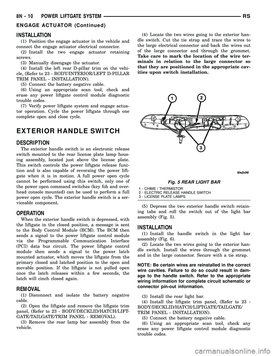
(5) Depress the two exterior handle switch retain-
ing tabs and roll the switch out of the light bar
assembly (Fig. 5).
INSTALLATION
(1) Install the handle switch in the light bar
assembly (Fig. 6).
(2) Locate the two wires going to the exterior han-
dle switch. Install the wires through the grommet
and in the large connector. Secure with a tie strap.
NOTE: Be certain wires are reinstalled in the correct
wire cavities. Failure to do so could result in dam-
age to the handle switch. Refer to the appropriate
wiring information for complete circuit schematic or
connector pin-out information.
(3) Install the rear light bar.
(4) Install the liftgate trim panel, (Refer to 23 -
BODY/DECKLID/HATCH/LIFTGATE/TAILGATE/
TRIM PANEL - INSTALLATION).
(5) Connect the battery negative cable.
(6) Using an appropriate scan tool, check any
erase any power liftgate control module diagnostic
trouble codes.
Fig. 5 REAR LIGHT BAR
1 - CHIME / THERMISTOR
2 - ELECTRIC RELEASE HANDLE SWITCH
3 - LICENSE PLATE LAMPS
8N - 10 POWER LIFTGATE SYSTEMRS
ENGAGE ACTUATOR (Continued)
Page 434 of 2339

(7) Verify power liftgate system and handle switch
operation. Cycle the power liftgate through one com-
plete open and close cycle, this will allow the power
liftgate control module to relearn its cycle with the
new components.
FULL OPEN SWITCH
DESCRIPTION
The full open switch is located on the gear motor
housing (Fig. 7) and is used to signal the power lift-
gate control module when the power liftgate is in the
full open position. Two wires are used from the full
open switch contacts to the gear motor assemblies
main electrical connector. The full open switch is a
serviceable component.
OPERATION
When the power liftgate reaches the full open posi-
tion, the gear motor housing mounted full open
switch electrical contacts close. This sends a ground
signal to the power liftgate control module, telling
the module that the liftgate has reached the full open
position.
REMOVAL
(1) Disconnect and isolate the battery negative
cable.
(2) Remove the lift gear and link rod assembly
from the vehicle(Refer to 8 - ELECTRICAL/POWER
DOORS/CONTROL ROD - REMOVAL).(3) Cut the two wires leading to the full open
switch or back the wires out of the electrical connec-
tor.
(4) Remove the full open switch retaining screw
and remove the full open switch from the gear motor
housing assembly.
INSTALLATION
(1) Perform a wiring repair on the full open switch
wires following the approved procedure in the Wiring
section of the service manual. Or install new termi-
nals on the wire ends and reinstall in the main lift-
gate motor electrical connector.
(2) Position and install the full open switch retain-
ing screw.
(3) Install the power liftgate lift gear and link rod
assembly. (Refer to 8 - ELECTRICAL/POWER
DOORS/CONTROL ROD - INSTALLATION)
(4) Connect the battery negative cable.
(5) Using an appropriate scan tool, check any
erase any power liftgate control module diagnostic
trouble codes.
(6) Verify power liftgate system and full open
switch operation. Cycle the power liftgate through
one complete open and close cycle, this will allow the
power liftgate control module to relearn its cycle with
the new components.
Fig. 6 REAR LIGHT BAR
1 - CHIME / THERMISTOR
2 - ELECTRIC RELEASE HANDLE SWITCH
3 - LICENSE PLATE LAMPS
Fig. 7 FULL OPEN SWITCH LOCATION
1 - FULL OPEN SWITCH
2 - GEAR MOTOR ASSEMBLY RETAINING BOLT (1 OF 3)
RSPOWER LIFTGATE SYSTEM8N-11
EXTERIOR HANDLE SWITCH (Continued)
Page 438 of 2339
LIFTGATE MOTOR
DESCRIPTION
The gear motor assembly (Fig. 14) consists of a DC
motor, hall effect sensor, engage actuator, full open
switch, lift gear, aluminum housing, drive gears and
wire harness. The gears and motor portion of the
assembly provides the power and torque required to
open or close the liftgate. The hall effect sensor is used
to provide the liftgate control module with a speed read-
ing, which is used to monitor the resistance of liftgate
travel. This speed reading also allows the power liftgate
control module to detect obstructions and move the lift-
gate accordingly. The engage actuator is used to toggle
between power open/close mode and full manual mode
when desired. The full open switch is used to let the
power liftgate control module know when the liftgate is
approaching the full open position.
Serviceable components of the power liftgate gear/mo-
tor assembly are the complete gear/motor assembly,
motor and wire harness, lift gear and control rod,
engage actuator, full open switch and the transverse
bracket.
OPERATION
With the push of a power liftgate command switch
(liftgate closed), the power liftgate control module
will signal the latch assembly to release the liftgate
from its primary closed and latched position to the
released and movable position. The liftgate motor-
mounted engage actuator then engages the liftgatemotor assembly, which moves the liftgate into the
open position. The liftgate motor provides the torque
and power to move the door to its full open or closed
position(Refer to 8 - ELECTRICAL/POWER DOORS -
OPERATION) for additional information.
REMOVAL
The power liftgate gear/motor assembly is serviced
in two ways: the complete gear/motor assembly, or
the motor, aluminum housing, drive gears and wire
harness assembly. To perform this service, use the
following procedure to remove the gear/motor assem-
bly from the vehicle. Then refer to the other proce-
dures called out in this section to transfer the
remaining components (engage actuator, full open
switch, transverse bracket and lift gear and rod) to
the replacement gear/motor assembly.
(1)
Disconnect and isolate the battery negative cable.
(2) Remove the left rear D-pillar trim panel from
the vehicle, (Refer to 23 - BODY/INTERIOR/LEFT
D-PILLAR TRIM PANEL - REMOVAL).
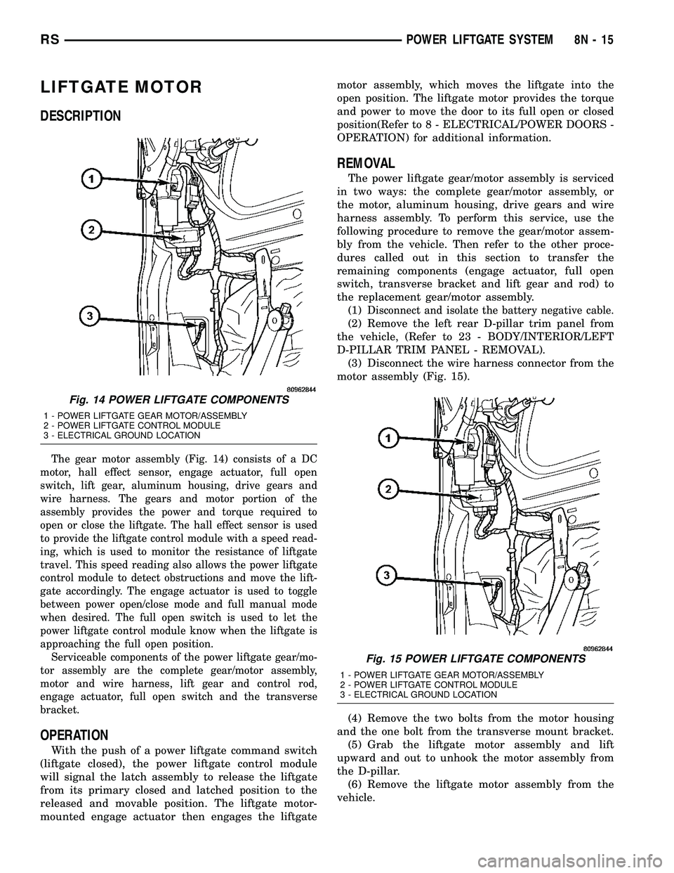
(3) Disconnect the wire harness connector from the
motor assembly (Fig. 15).
(4) Remove the two bolts from the motor housing
and the one bolt from the transverse mount bracket.
(5) Grab the liftgate motor assembly and lift
upward and out to unhook the motor assembly from
the D-pillar.
(6) Remove the liftgate motor assembly from the
vehicle.
Fig. 14 POWER LIFTGATE COMPONENTS
1 - POWER LIFTGATE GEAR MOTOR/ASSEMBLY
2 - POWER LIFTGATE CONTROL MODULE
3 - ELECTRICAL GROUND LOCATION
Fig. 15 POWER LIFTGATE COMPONENTS
1 - POWER LIFTGATE GEAR MOTOR/ASSEMBLY
2 - POWER LIFTGATE CONTROL MODULE
3 - ELECTRICAL GROUND LOCATION
RSPOWER LIFTGATE SYSTEM8N-15
Page 439 of 2339

INSTALLATION
(1) Using the motor housing tab, hook the liftgate
motor assembly on the D-pillar.
(2) Install the three motor assembly retaining
bolts. Torque the two rear most bolts first to 9.5 N´m
(85 in. lbs.). Torque the remaining bolt next to the
window actuator to 9.5 N´m (85 in. lbs.).
(3) Connect the liftgate motor assembly electrical
connector.
(4) Install the D-pillar trim panel on the vehicle,
(Refer to 23 - BODY/INTERIOR/LEFT D-PILLAR
TRIM PANEL - INSTALLATION).
(5) Connect the battery negative cable.
(6) Using an appropriate scan tool, check any
erase any power liftgate control module diagnostic
trouble codes related to the door motor assembly.
(7) Verify power liftgate system operation. Cycle
the power liftgate through one complete open and
close cycle, this will allow the power liftgate control
module to relearn its cycle with the new components.
LIFT GEAR & LINK ROD
DESCRIPTION
The lift gear and rod assembly are located in the
left rear of the vehicle and are visible without remov-ing the D-pillar trim (Fig. 16). The lift gear provides
the leverage to move the liftgate from the closed to
the open position. The lift gear attaches to a bearing
on the gear motor assembly with four bolts. On the
outboard side of the lift gear are riveted on teeth,
which mesh with the gear motor assembly drive
gears during a open or close operation. The rod
assembly is a steel shaft, equipped with two spheri-
cal rod ends which attaches the lift gear to the lift-
gate. The lift gear and rod assembly are serviceable
components.
OPERATION
One end of the rod assembly is attached to the lift-
gate, the other attached to the lift gear. When the lift
gear is driven by the gear motor assembly the lift-
gate is moved to the open or closed position.
REMOVAL
(1) Disconnect and isolate the battery negative
cable.
(2) Remove the left rear D-pillar trim panel from
the vehicle, (Refer to 23 - BODY/INTERIOR/LEFT
D-PILLAR TRIM PANEL - REMOVAL).
(3) Remove the lift gear retaining bolts (Fig. 17).
(4) Remove the lift gear and rod from the vehicle.
Fig. 16 LIFTGATE GEAR/MOTOR ASSEMBLY
1 - TRANSVERSE BRACKET
2 - ENGAGE ACTUATOR
3 - LIFT GEAR AND ROD ASSEMBLY
4 - LIFTGATE MOTOR
Fig. 17 LIFTGATE GEAR MOTOR ASSEMBLY
1 - ENGAGE ACTUATOR RETAINING SCREWS
2 - LIFT GEAR RETAINING BOLTS
8N - 16 POWER LIFTGATE SYSTEMRS
LIFTGATE MOTOR (Continued)
Page 442 of 2339

TRANSVERSE BRACKET
DESCRIPTION
The transverse bracket (Fig. 22) is used to support
and secure the power liftgate gear/motor assembly to
the left rear body D-pillar. The transverse bracket is
a serviceable power liftgate component.
OPERATION
The power liftgate transverse bracket supports the
gear motor assembly by supplying an additional
attachment point. Located on the leading edge of the
gear motor assembly, one end of the transverse
bracket attaches to the motor assembly the other to
the leading edge of the vehicles D-pillar.
REMOVAL
(1) Disconnect and isolate the battery negative
cable.
(2) Remove the left D-pillar trim from the vehicle,
(Refer to 23 - BODY/INTERIOR/LEFT D-PILLAR
TRIM PANEL - REMOVAL).
(3) Disconnect the gear motor assembly electrical
connector and disengage retaining pushpin.
(4) Loosen the gear motor assembly retaining bolts
to allow room for transverse bracket to be removed.
(5) Remove the transverse bracket retaining bolts
(Fig. 23).
(6)
Remove the transverse bracket from the vehicle.
INSTALLATION
(1) Position the transverse bracket in the vehicle.
Be certain the transverse bracket is properly posi-
tioned. The bracket should just touch the engage
actuator arm and be positioned between the actuator
arm and the motor housing.
(2) Torque the transverse bracket retaining bolts
to the gear motor assembly to 9.5 N´m (85 in. lbs.).
Do not tighten the transverse bracket retaining bolt,
located under the window actuator at this time.
(3) Torque the gear motor assembly retaining bolts
to 9.5 N´m (85 in. lbs.).
(4) Torque the final transverse bracket retaining
bolt to 9.5 N´m (85 in. lbs.).
(5) Connect the gear motor assembly electrical con-
nector and engage retaining pushpin.
(6) Install the left D-pillar trim, (Refer to 23 -
BODY/INTERIOR/LEFT D-PILLAR TRIM PANEL -
INSTALLATION).
(7) Connect the battery negative cable.
(8) Using an appropriate scan tool, check any
erase any power liftgate control module diagnostic
trouble codes related to the door motor assembly.
(9) Verify power liftgate system operation. Cycle
the power liftgate through one complete open and
close cycle, this will allow the power liftgate control
module to relearn its cycle with the new components.
Fig. 22 LIFTGATE GEAR/MOTOR ASSEMBLY
1 - TRANSVERSE BRACKET
2 - ENGAGE ACTUATOR
3 - LIFT GEAR AND ROD ASSEMBLY
4 - LIFTGATE MOTOR
Fig. 23 LIFTGATE GEAR MOTOR ASSEMBLY
1 - TRANSVERSE BRACKET
2 - ENGAGE ACTUATOR
3 - LIFT GEAR AND ROD ASSEMBLY
4 - LIFTGATE MOTOR
RSPOWER LIFTGATE SYSTEM8N-19
Page 449 of 2339
POWER MIRRORS
TABLE OF CONTENTS
page page
POWER MIRRORS
DESCRIPTION.........................26
OPERATION...........................26
DIAGNOSIS AND TESTING
POWER MIRRORS....................27
AUTOMATIC DAY / NIGHT MIRROR
DESCRIPTION.........................28
OPERATION...........................28
DIAGNOSIS AND TESTING
AUTOMATIC DAY / NIGHT MIRROR.......28
POWER FOLDAWAY MIRROR SWITCH -
EXPORT
DESCRIPTION.........................29OPERATION...........................29
REMOVAL.............................29
INSTALLATION.........................30
REMOTE SWITCH
DIAGNOSIS AND TESTING
REMOTE SWITCH.....................30
REMOVAL.............................30
INSTALLATION.........................30
SIDEVIEW MIRROR
REMOVAL.............................30
POWER MIRRORS
DESCRIPTION
If equipped with power mirrors, the control switch
is located on the instrument panel to the left of the
headlamp switch.
OPERATION
The power mirrors are connected to battery feed at
all times. Each mirror head contains two electric
motors, two drive mechanisms, an electric heating
element, and the mirror glass. If the vehicle is
equipped with the optional memory system, the
driver side mirror head also contains both a horizon-
tal and a vertical motor position sensor. One motor
and drive controls mirror up-and-down movement,
and the other controls right-and-left movement.An optional driver side outside electrochromic mir-
ror is able to automatically change its reflectance
level. This mirror is controlled by the circuitry of the
automatic day/night inside rear view mirror. A thin
layer of electrochromic material between two pieces
of conductive glass make up the face of the mirror.
Two photocell sensors on the inside rear view mirror
are used to monitor light levels and adjust the reflec-
tance of both the inside and driver side outside mir-
rors. This change in reflectance helps to reduce the
glare of headlamps approaching the vehicle from the
rear. (Refer to 8 - ELECTRICAL/POWER MIRRORS/
AUTOMATIC DAY / NIGHT MIRROR - DESCRIP-
TION) for more information on this system.
The motors which operate the mirrors are part of
the mirror assembly and cannot be serviced sepa-
rately.
8N - 26 POWER MIRRORSRS
Page 451 of 2339
AUTOMATIC DAY / NIGHT
MIRROR
DESCRIPTION
An automatic dimming inside day/night rear view
mirror and an automatic dimming driver side outside
rear view mirror are available factory-installed
options on this model. Following is a general descrip-
tion of this optional equipment.
The automatic day/night mirror is able to automat-
ically change its reflectance. A thin layer of electro-
chromic material between two pieces of conductive
glass make up the face of the mirror. Two photocell
sensors are used to monitor light levels and adjust
the reflectance of the mirror to reduce the glare of
headlamps approaching the vehicle from the rear.
For removal procedures, (Refer to 23 - BODY/IN-
TERIOR/REAR VIEW MIRROR - REMOVAL).
OPERATION
The ambient photocell sensor faces forward, to
detect the outside light levels. A second sensor faces
rearward to detect the light level received through
the vehicles back window. When the difference
between the two light levels becomes too great (the
light level received at the rear of the mirror is much
higher than that at the front of the mirror), the mir-
ror begins to darken.
The mirror switch allows the driver a manual con-
trol of whether the automatic dimming feature is
operational. When AUTO is selected a small Light-
Emitting Diode (LED), to the right of the mirror
switch, is illuminated. The automatic dimming fea-
ture will only operate when the ignition switch is in
the On position. The mirror also senses the backup
lamp circuit, and will automatically disable its self-
dimming feature whenever the transmission gear
selector is in the Reverse position.
NOTE: The mirror always defaults to an ON state
upon ignition.
The driver side automatic dimming mirror is stan-
dard with the automatic dimming inside mirror. The
signal to control the dimming of that mirror is gen-
erated by the automatic day/night inside rear view
mirror circuitry. That signal is then delivered to the
driver side outside rear view mirror on a hard wired
circuit.
The automatic day/night mirror cannot be
repaired. If faulty or damaged, the entire inside rear
view mirror assembly must be replaced.
DIAGNOSIS AND TESTING
AUTOMATIC DAY / NIGHT MIRROR
For circuit descriptions and diagrams, refer to the
appropriate wiring information. The wiring informa-
tion includes wiring diagrams, proper wire and con-
nector repair procedures, details of wire harness
routing and retention, connector pin-out information
and location views for the various wire harness con-
nectors, splices and grounds.
(1) Check the fuse in the intelligent power module.
If OK, go to Step 2. If not OK, repair the shorted cir-
cuit or component as required and replace the faulty
fuse.
(2) Turn the ignition switch to the On position.
Check for battery voltage at the fuse in the intelli-
gent power module. If OK, go to Step 3. If not OK,
repair the open circuit to the ignition switch as
required.
(3) Unplug the wire harness connector from the
automatic day/night mirror. Check for battery voltage
at the fused ignition switch output circuit cavity of
the automatic day/night mirror wire harness connec-
tor. If OK, go to Step 4. If not OK, repair the open
circuit to the junction block as required.
(4) Turn the ignition switch to the Off position.
Check for continuity between the ground circuit cav-
ity of the automatic day/night mirror wire harness
connector and a good ground. There should be conti-
nuity. If OK, go to Step 5. If not OK, repair the cir-
cuit to ground as required.
(5) Turn the ignition switch to the On position. Set
the parking brake. Place the transmission gear selec-
tor lever in the Reverse position. Check for battery
voltage at the backup lamp switch output circuit cav-
ity of the automatic day/night mirror wire harness
connector. If voltage is present, reinstall the auto-
matic day/night mirror wire harness connector and
go to Step 6. If not OK, repair the open circuit as
required.
(6) Place the transmission gear selector lever in
the Neutral position. Place the automatic day/night
mirror switch in the On (LED in the switch is
lighted) position. Cover the forward facing ambient
photocell sensor to keep out any ambient light.
NOTE: The ambient photocell sensor must be cov-
ered completely, so that no light reaches the sen-
sor. Use a finger pressed tightly against the sensor,
or cover the sensor completely with electrical tape.
(7) Shine a light into the rearward facing head-
lamp photocell sensor. The automatic day/night mir-
ror should darken. The automatic day/night mirror
should darken within 2 minutes if testing for the
first time. For immediate response, turn the vehicle
8N - 28 POWER MIRRORSRS
Page 452 of 2339
OFF and back ON with the forward-facing light sen-
sor still covered. This defeats the day-detect logic. If
OK, go to Step 8. If not OK, replace the faulty mirror
unit.
(8) With the mirror darkened, place the transmis-
sion gear selector lever in the Reverse position. The
automatic day/night mirror should return to its nor-
mal reflectance. If not OK, replace the faulty mirror
unit.
Bench testing both mirrors can be done, of care is
exercised. For an inside mirror, the pin closest to he
mount is 12V (+), the next is 12V (-). The third is
reverse override. The fourth is outside mirror (+), and
the fifth is outside mirror (-).Do not apply 12 volts to
the fourth and fifth pins.With 12 volts on pins 1 and
2, the mirror can be tested by blocking the rear sensor
and shining a light into the forward sensor. For an out-
side mirror, there is a 2±pin connector. Applying 1.2
volts will cause the mirror to dim. If the mirror does not
dim, the entire glass assembly can be replaced just as it
is when the glass is broken.
WARNING: Do not apply 12 volts to the outside mir-
ror. Damage to the mirror will result.
POWER FOLDAWAY MIRROR
SWITCH - EXPORT
DESCRIPTION
These vehicles may be equipped with Power Fold-
away Mirrors. This feature allows both the driver
and passenger side view mirrors to fold inward
(retract) on demand. The vehicle has an additional
switch located on the steering column that controls
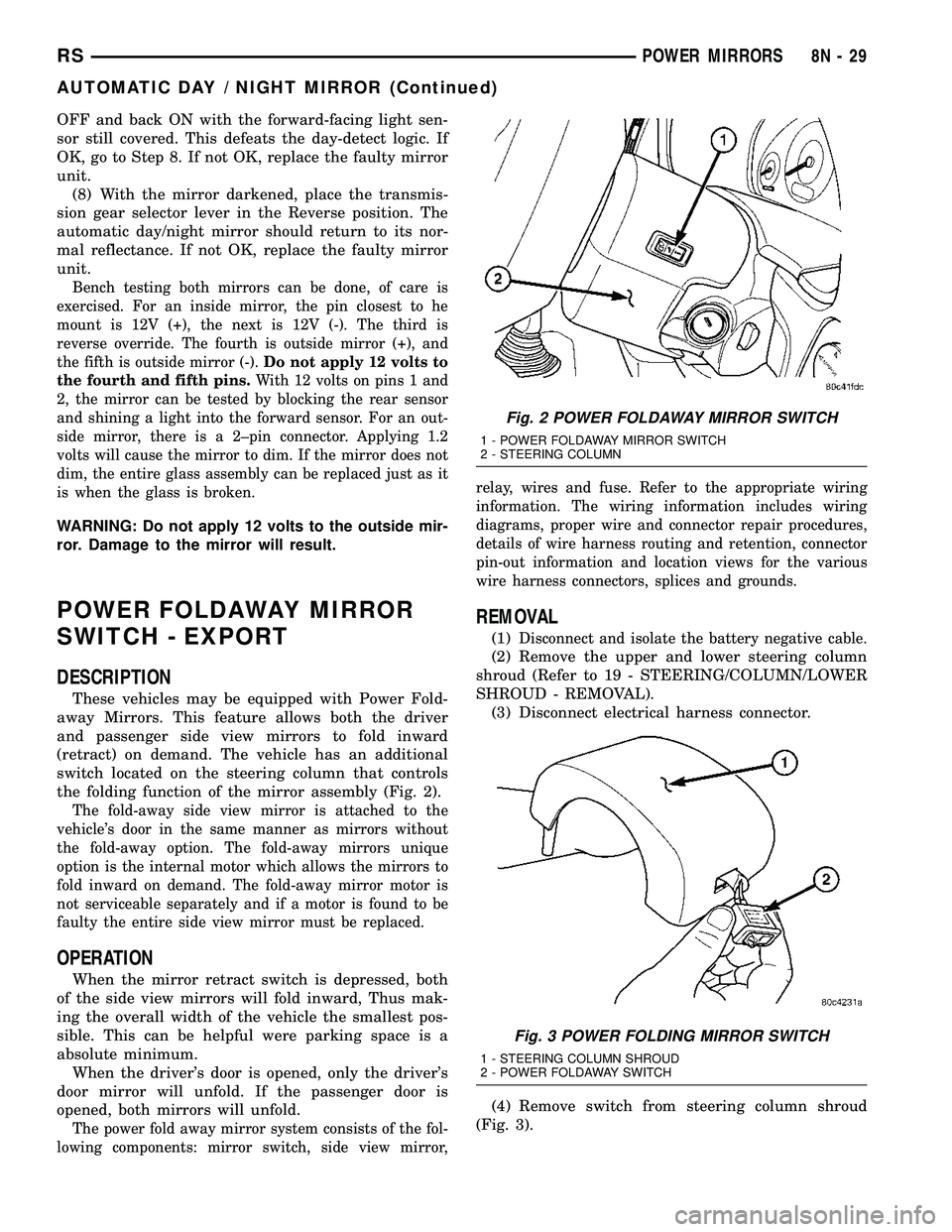
the folding function of the mirror assembly (Fig. 2).
The fold-away side view mirror is attached to the
vehicle's door in the same manner as mirrors without
the fold-away option. The fold-away mirrors unique
option is the internal motor which allows the mirrors to
fold inward on demand. The fold-away mirror motor is
not serviceable separately and if a motor is found to be
faulty the entire side view mirror must be replaced.
OPERATION
When the mirror retract switch is depressed, both
of the side view mirrors will fold inward, Thus mak-
ing the overall width of the vehicle the smallest pos-
sible. This can be helpful were parking space is a
absolute minimum.
When the driver's door is opened, only the driver's
door mirror will unfold. If the passenger door is
opened, both mirrors will unfold.
The power fold away mirror system consists of the fol-
lowing components: mirror switch, side view mirror,relay, wires and fuse. Refer to the appropriate wiring
information. The wiring information includes wiring
diagrams, proper wire and connector repair procedures,
details of wire harness routing and retention, connector
pin-out information and location views for the various
wire harness connectors, splices and grounds.
REMOVAL
(1)Disconnect and isolate the battery negative cable.
(2) Remove the upper and lower steering column
shroud (Refer to 19 - STEERING/COLUMN/LOWER
SHROUD - REMOVAL).
(3) Disconnect electrical harness connector.
(4) Remove switch from steering column shroud
(Fig. 3).
Fig. 2 POWER FOLDAWAY MIRROR SWITCH
1 - POWER FOLDAWAY MIRROR SWITCH
2 - STEERING COLUMN
Fig. 3 POWER FOLDING MIRROR SWITCH
1 - STEERING COLUMN SHROUD
2 - POWER FOLDAWAY SWITCH
RSPOWER MIRRORS8N-29
AUTOMATIC DAY / NIGHT MIRROR (Continued)
Page 454 of 2339

POWER SEAT SYSTEM
TABLE OF CONTENTS
page page
POWER SEAT SYSTEM
DESCRIPTION
POWER SEAT SYSTEM................31
MEMORY SYSTEM....................32
OPERATION
POWER SEAT SYSTEM................32
MEMORY SYSTEM....................33
DIAGNOSIS AND TESTING
POWER SEAT SYSTEM................33
MEMORY SYSTEM....................33
SEAT SWITCH
DESCRIPTION.........................34
OPERATION...........................34
DIAGNOSIS AND TESTING
DRIVER SEAT SWITCH.................34
REMOVAL.............................36INSTALLATION.........................36
MEMORY SWITCH
DESCRIPTION.........................36
OPERATION...........................36
DIAGNOSIS AND TESTING
MEMORY SWITCH....................37
REMOVAL.............................37
INSTALLATION.........................37
POWER SEAT TRACK
DESCRIPTION.........................37
OPERATION...........................38
DIAGNOSIS AND TESTING
POWER SEAT TRACK..................38
REMOVAL.............................38
INSTALLATION.........................39
POWER SEAT SYSTEM
DESCRIPTION
POWER SEAT SYSTEM
The power seat system option allows the driver
and front seat passenger to electrically adjust their
seating positions for optimum control and comfort.
The driver side power front seat can be adjusted in
eight different directions: up, down, front up, front
down, rear up, rear down, forward, rearward and
recliner forward and rearward. The passenger side
power front seat can be adjusted in four different
directions: forward, rearward and recliner forward
and rearward.
The power seat system receives battery current
through a 40 amp fuse in the Integrated Power Mod-
ule (IPM) and a 30 amp circuit breaker under the
seat so that the power seats remain operational,
regardless of the ignition switch position.
WARNING: SOME VEHICLES ARE EQUIPPED WITH
SEATBACK MOUNTED AIRBAGS (Fig. 1). BEFORE
ATTEMPTING TO DIAGNOSE OR SERVICE ANY
SEAT OR POWER SEAT SYSTEM COMPONENT
YOU MUST FIRST DISCONNECT AND ISOLATE THE
BATTERY NEGATIVE CABLE. THEN WAIT TWO MIN-
UTES FOR THE SYSTEM CAPACITOR TO DIS-
CHARGE BEFORE FURTHER SYSTEM SERVICE.
THIS IS THE ONLY SURE WAY TO DISABLE THE
AIRBAG SYSTEM. FAILURE TO DO SO COULDRESULT IN ACCIDENTAL AIRBAG DEPLOYMENT
AND POSSIBLE PERSONAL INJURY.
The eight-way driver side power seat is also avail-
able with the heated seat and/or memory seat sys-
tem. The memory seat system automatically
positions the power seat for two different drivers.
Fig. 1 IDENTIFYING A SIDE AIRBAG EQUIPPED
SEAT
1 - AIRBAG LABEL
RSPOWER SEAT SYSTEM8N-31