torque CHRYSLER VOYAGER 2005 Manual Online
[x] Cancel search | Manufacturer: CHRYSLER, Model Year: 2005, Model line: VOYAGER, Model: CHRYSLER VOYAGER 2005Pages: 2339, PDF Size: 59.69 MB
Page 293 of 2339
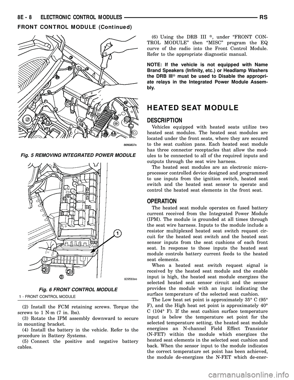
(2) Install the FCM retaining screws. Torque the
screws to 1 N´m (7 in. lbs).
(3) Rotate the IPM assembly downward to secure
in mounting bracket.
(4) Install the battery in the vehicle. Refer to the
procedure in Battery Systems.
(5) Connect the positive and negative battery
cables.(6) Using the DRB IIIt, under ªFRONT CON-
TROL MODULEº then ªMISCº program the EQ
curve of the radio into the Front Control Module.
Refer to the appropriate diagnostic manual.
NOTE: If the vehicle is not equipped with Name
Brand Speakers (Infinity, etc.) or Headlamp Washers
the DRB IIITmust be used to Disable the appropri-
ate relays in the Integrated Power Module Assem-
bly.
HEATED SEAT MODULE
DESCRIPTION
Vehicles equipped with heated seats utilize two
heated seat modules. The heated seat modules are
located under the front seats, where they are secured
to the seat cushion pans. Each heated seat module
has three connector receptacles that allow the mod-
ules to be connected to all of the required inputs and
outputs through the seat wire harness.
The heated seat modules are an electronic micro-
processor controlled device designed and programmed
to use inputs from the ignition switch, heated seat
switch and the heated seat sensor to operate and
control the heated seat elements in the front seat.
OPERATION
The heated seat module operates on fused battery
current received from the Integrated Power Module
(IPM). The module is grounded at all times through
the seat wire harness. Inputs to the module include a
resistor multiplexed heated seat switch request cir-
cuit for the heated seat switch and the heated seat
sensor inputs from the seat cushions of each front
seat. In response to those inputs the heated seat
module controls battery current feeds to the heated
seat elements.
When a heated seat switch request signal is
received by the heated seat module and the enable
input is high, the heated seat module energizes the
selected heated seat sensor circuit and the sensor
provides the module with an input indicating the
surface temperature of the selected seat cushion.
The Low heat set point is approximately 35É C (95É
F), and the High heat set point is approximately 40É
C (104É F). If the seat cushion surface temperature
input is below the temperature set point for the
selected temperature setting, the heated seat module
energizes an N-channel Field Effect Transistor
(N-FET) within the module which energizes the
heated seat elements in the selected seat cushion and
back. When the sensor input to the module indicates
the correct temperature set point has been achieved,
the module de-energizes the N-FET which de-ener-
Fig. 5 REMOVING INTEGRATED POWER MODULE
Fig. 6 FRONT CONTROL MODULE
1 - FRONT CONTROL MODULE
8E - 8 ELECTRONIC CONTROL MODULESRS
FRONT CONTROL MODULE (Continued)
Page 297 of 2339
²SCI Receive
²Speed Control
²Throttle Position Sensor
²Transmission Control Relay (Switched B+)
²Transmission Pressure Switches
²Transmission Temperature Sensor
²Transmission Input Shaft Speed Sensor
²Transmission Output Shaft Speed Sensor
²Transaxle Gear Engagement
²Vehicle Speed
NOTE: PCM Outputs:
²Air Conditioning Clutch Relay
²Automatic Shut Down (ASD) and Fuel Pump
Relays
²Data Link Connector (PCI and SCI Transmit)
²Double Start Override
²EGR Solenoid
²Fuel Injectors
²Generator Field
²High Speed Fan Relay
²Idle Air Control Motor
²Ignition Coils
²Leak Detection Pump
²Low Speed Fan Relay
²MTV Actuator
²Proportional Purge Solenoid
²SRV Valve
²Speed Control Relay
²Speed Control Vent Relay
²Speed Control Vacuum Relay
²8 Volt Output
²5 Volt Output
²Torque Reduction Request
²Transmission Control Relay
²Transmission Solenoids
²Vehicle Speed
Based on inputs it receives, the powertrain control
module (PCM) adjusts fuel injector pulse width, idle
speed, ignition timing, and canister purge operation.
The PCM regulates the cooling fans, air conditioning
and speed control systems. The PCM changes gener-
ator charge rate by adjusting the generator field.
The PCM adjusts injector pulse width (air-fuel
ratio) based on the following inputs.
²Battery Voltage
²Intake Air Temperature Sensor
²Engine Coolant Temperature
²Engine Speed (crankshaft position sensor)
²Exhaust Gas Oxygen Content (heated oxygen
sensors)
²Manifold Absolute Pressure
²Throttle Position
The PCM adjusts engine idle speed through the
idle air control motor based on the following inputs.
²Brake Switch²Engine Coolant Temperature
²Engine Speed (crankshaft position sensor)
²Park/Neutral
²Transaxle Gear Engagement
²Throttle Position
²Vehicle Speed
The PCM adjusts ignition timing based on the fol-
lowing inputs.
²Intake Air Temperature
²Engine Coolant Temperature
²Engine Speed (crankshaft position sensor)
²Knock Sensor
²Manifold Absolute Pressure
²Park/Neutral
²Transaxle Gear Engagement
²Throttle Position
The automatic shut down (ASD) and fuel pump
relays are mounted externally, but turned on and off
by the powertrain control module through the same
circuit.
The camshaft and crankshaft signals are sent to
the powertrain control module. If the PCM does not
receive both signals within approximately one second
of engine cranking, it deactivates the ASD and fuel
pump relays. When these relays are deactivated,
power is shut off to the fuel injectors, ignition coils,
fuel pump and the heating element in each oxygen
sensor.
The PCM contains a voltage converter that
changes battery voltage to a regulated 8.0 volts. The
8.0 volts power the camshaft position sensor, crank-
shaft position sensor and vehicle speed sensor. The
PCM also provides a 5.0 volts supply for the engine
coolant temperature sensor, intake air temperature
sensor, manifold absolute pressure sensor and throt-
tle position sensor.
The PCM engine control strategy prevents reduced
idle speeds until after the engine operates for 320 km
(200 miles). If the PCM is replaced after 320 km (200
miles) of usage, update the mileage in new PCM. Use
the DRBIIItscan tool to change the mileage in the
PCM. Refer to the appropriate Powertrain Diagnostic
Manual and the DRBIIItscan tool.
TRANSMISSION CONTROL
CLUTCH VOLUME INDEX (CVI)
An important function of the PCM is to monitor
Clutch Volume Index (CVI). CVIs represent the vol-
ume of fluid needed to compress a clutch pack.
The PCM monitors gear ratio changes by monitor-
ing the Input and Output Speed Sensors. The Input,
or Turbine Speed Sensor sends an electrical signal to
the PCM that represents input shaft rpm. The Out-
put Speed Sensor provides the PCM with output
shaft speed information.
8E - 12 ELECTRONIC CONTROL MODULESRS
POWERTRAIN CONTROL MODULE (Continued)
Page 299 of 2339
Schedule Condition Expected Operation
Extreme ColdOil temperature at start-up below
-16É FPark, Reverse, Neutral and 2nd
gear only (prevents shifting which
may fail a clutch with frequent
shifts)
ColdOil temperature at start-up above
-12É F and below 36É F± Delayed 2-3 upshift
(approximately 22-31 mph)
± Delayed 3-4 upshift (45-53 mph)
± Early 4-3 costdown shift
(approximately 30 mph)
± Early 3-2 coastdown shift
(approximately 17 mph)
± High speed 4-2, 3-2, 2-1 kickdown
shifts are prevented
± No EMCC
WarmOil temperature at start-up above
36É F and below 80 degree F± Normal operation (upshift,
kickdowns, and coastdowns)
± No EMCC
HotOil temperature at start-up above
80É F± Normal operation (upshift,
kickdowns, and coastdowns)
± Full EMCC, no PEMCC except to
engage FEMCC (except at closed
throttle at speeds above 70-83 mph)
OverheatOil temperature above 240É F or
engine coolant temperature above
244É F± Delayed 2-3 upshift (25-32 mph)
± Delayed 3-4 upshift (41-48 mph)
± 3rd gear FEMCC from 30-48 mph
± 3rd gear PEMCC from 27-31 mph
Super OverheatOil temperature above 260É F ± All9Overheat9shift schedule
features apply
± 2nd gear PEMCC above 22 mph
± Above 22 mph the torque
converter will not unlock unless the
throttle is closed or if a wide open
throttle 2nd PEMCC to 1 kickdown
is made
OPERATION - SENSOR RETURN - PCM INPUT
The sensor return circuit provides a low electrical
noise ground reference for all of the systems sensors.
The sensor return circuit connects to internal ground
circuits within the Powertrain Control Module
(PCM).
OPERATION - DATA BUS COMMUNICATION
RECEIVE - PCM INPUT
The PCM uses the SCI communication bus to pre-
form engine diagnostics and flash operations. The
transmission side of the PCM uses the SCI commu-
nication bus to flash new software. However, diagnos-tics is performed via the vehicles J1850 bus for the
transmission side of the PCM.
OPERATION - IGNITION SENSE - PCM INPUT
The ignition sense input informs the Powertrain
Control Module (PCM) that the ignition switch is in
the crank or run position.
OPERATION - PCM GROUND
Ground is provided through multiple pins of the
PCM connector. Depending on the vehicle there may
be as many as two different ground pins. There are
power grounds and sensor grounds.
8E - 14 ELECTRONIC CONTROL MODULESRS
POWERTRAIN CONTROL MODULE (Continued)
Page 321 of 2339
press the ENTER button to view the SERVICE
CODE. Pressing the CODE button a second time will
return you to the test results.
BATTERY TEST RESULTS
GOOD BATTERY Return to service
GOOD - RECHARGE Fully charge battery and
return to service
CHARGE & RETEST Fully charge battery and
retest battery
REPLACE BATTERY Replace the battery and
retest complete system
BAD-CELL REPLACE Replace the battery and
retest complete system
NOTE: The SERVICE CODE is required on every
warranty claim submitted for battery replacement.
REMOVAL - BATTERY
WARNING: A SUITABLE PAIR OF HEAVY DUTY
RUBBER GLOVES AND SAFETY GLASSES SHOULD
BE WORN WHEN REMOVING OR SERVICING A
BATTERY.
WARNING: REMOVE METALLIC JEWELRY TO
AVOID INJURY BY ACCIDENTAL ARCING OF BAT-
TERY CURRENT.
(1) Verify that the ignition switch and all accesso-
ries are OFF.
(2) Disconnect the battery cables from the battery
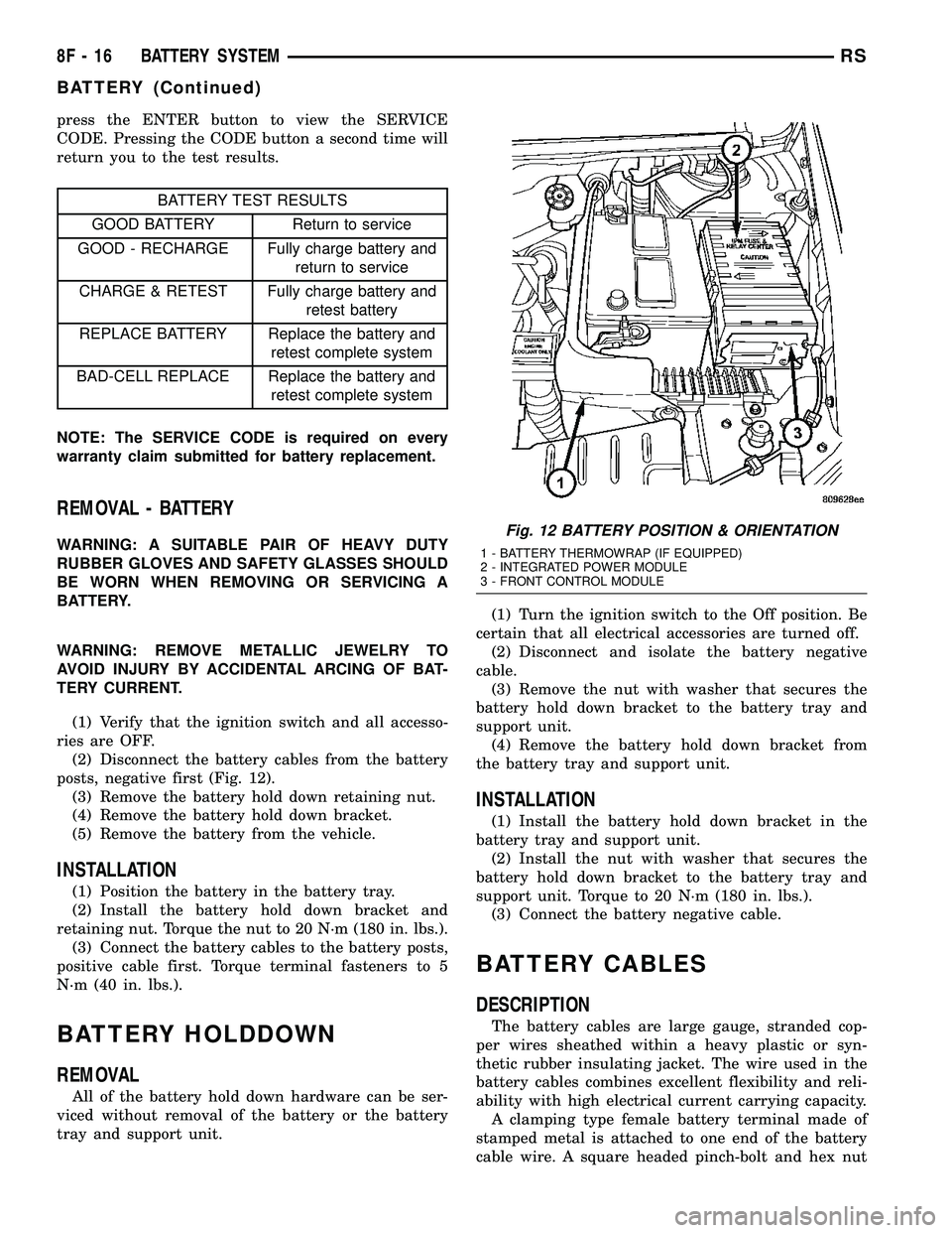
posts, negative first (Fig. 12).
(3) Remove the battery hold down retaining nut.
(4) Remove the battery hold down bracket.
(5) Remove the battery from the vehicle.
INSTALLATION
(1) Position the battery in the battery tray.
(2) Install the battery hold down bracket and
retaining nut. Torque the nut to 20 N´m (180 in. lbs.).
(3) Connect the battery cables to the battery posts,
positive cable first. Torque terminal fasteners to 5
N´m (40 in. lbs.).
BATTERY HOLDDOWN
REMOVAL
All of the battery hold down hardware can be ser-
viced without removal of the battery or the battery
tray and support unit.(1) Turn the ignition switch to the Off position. Be
certain that all electrical accessories are turned off.
(2) Disconnect and isolate the battery negative
cable.
(3) Remove the nut with washer that secures the
battery hold down bracket to the battery tray and
support unit.
(4) Remove the battery hold down bracket from
the battery tray and support unit.
INSTALLATION
(1) Install the battery hold down bracket in the
battery tray and support unit.
(2) Install the nut with washer that secures the
battery hold down bracket to the battery tray and
support unit. Torque to 20 N´m (180 in. lbs.).
(3) Connect the battery negative cable.
BATTERY CABLES
DESCRIPTION
The battery cables are large gauge, stranded cop-
per wires sheathed within a heavy plastic or syn-
thetic rubber insulating jacket. The wire used in the
battery cables combines excellent flexibility and reli-
ability with high electrical current carrying capacity.
A clamping type female battery terminal made of
stamped metal is attached to one end of the battery
cable wire. A square headed pinch-bolt and hex nut
Fig. 12 BATTERY POSITION & ORIENTATION
1 - BATTERY THERMOWRAP (IF EQUIPPED)
2 - INTEGRATED POWER MODULE
3 - FRONT CONTROL MODULE
8F - 16 BATTERY SYSTEMRS
BATTERY (Continued)
Page 326 of 2339
CHARGING
TABLE OF CONTENTS
page page
CHARGING
DESCRIPTION - CHARGING SYSTEM.......21
OPERATION - CHARGING SYSTEM.........21
DIAGNOSIS AND TESTING
ON-BOARD DIAGNOSTIC SYSTEM........22
SPECIFICATIONS
GENERATOR........................23
TORQUE............................23
SPECIFICATIONS - BATTERY
TEMPERATURE SENSOR...............23
SPECIAL TOOLS.......................24
BATTERY TEMPERATURE SENSOR
DESCRIPTION.........................24
OPERATION...........................24
REMOVAL.............................24
GENERATOR
DESCRIPTION.........................24
OPERATION...........................24REMOVAL
REMOVAL - 2.4L......................24
REMOVAL - 2.5L......................25
REMOVAL - 3.3/3.8L...................27
INSTALLATION
INSTALLATION - 2.4L..................27
INSTALLATION - 2.5L..................27
INSTALLATION - 3.3/3.8L................27
GENERATOR DECOUPLER PULLEY
DESCRIPTION.........................28
OPERATION...........................28
DIAGNOSIS AND TESTING - GENERATOR
DECOUPLER PULLEY..................28
REMOVAL.............................29
INSTALLATION.........................29
VOLTAGE REGULATOR
DESCRIPTION.........................30
OPERATION...........................30
CHARGING
DESCRIPTION - CHARGING SYSTEM
The charging system consists of:
²Generator
²Decoupler Pulley (If equipped)
²Electronic Voltage Regulator (EVR) circuitry
within the Powertrain Control Module (PCM)
²Ignition switch (refer to the Ignition System sec-
tion for information)
²Battery (refer to the Battery section for informa-
tion)
²Ambient Air Temperature (If equipped)
²Inlet Air Temperature (calculated battery tem-
perature)(If equipped)
²Voltmeter (refer to the Instrument Cluster sec-
tion for information if equipped)
²Wiring harness and connections (refer to the
Wiring section for information)
²Accessory drive belt (refer to the Cooling section
for more information)
²Battery Temperature sensor (if equipped)
OPERATION - CHARGING SYSTEM
The charging system is turned on and off with the
ignition switch. The system is on when the engine is
running and the ASD relay is energized. The ASD
relay is energized when the PCM grounds the ASD
control circuit. This voltage is connected through thePCM or IPM (intelligent power module) (if equipped)
and supplied to one of the generator field terminals
(Gen. Source +) at the back of the generator.
The generator is driven by the engine through a
serpentine belt and pulley or decoupler pulley
arrangement.
The amount of DC current produced by the gener-
ator is controlled by the EVR (field control) circuitry
contained within the PCM. This circuitry is con-
nected in series with the second rotor field terminal
and ground.
An Ambient air temperature sensor is used to cal-
culate the temperature near the battery. This tem-
perature data, along with data from monitored line
voltage (battery voltage sense circuit), is used by the
PCM to vary the battery charging rate. This is done
by cycling the ground path to control the strength of
the rotor magnetic field. The PCM then compensates
and regulates generator current output accordingly
to maintain system voltage at the targeted system
voltage based on battery temperature.
All vehicles are equipped with On-Board Diagnos-
tics (OBD). All OBD-sensed systems, including EVR
(field control) circuitry, are monitored by the PCM.
Each monitored circuit is assigned a Diagnostic Trou-
ble Code (DTC). The PCM will store a DTC in elec-
tronic memory for certain failures it detects and
illuminate the (MIL) lamp. Refer to On-Board Diag-
nostics in the Electronic Control Modules(Refer to 8 -
ELECTRICAL/ELECTRONIC CONTROL MOD-
RSCHARGING8F-21
Page 328 of 2339
torque specifications (Refer to 8 - ELECTRICAL/
CHARGING - SPECIFICATIONS).
(5) Inspect generator drive belt condition and ten-
sion. Tighten or replace belt as required. Refer to
Belt Tension Specifications(Refer to 7 - COOLING/
ACCESSORY DRIVE - SPECIFICATIONS).
(6) Inspect decoupler pulley (if equipped). Ensure
decoupler pulley is driving the alternator rotor.(7) Inspect automatic belt tensioner (if equipped).
Refer to the Cooling System for more information.
(8) Inspect generator electrical connections at gen-
erator field, battery output, and ground terminal (if
equipped). Also check generator ground wire connec-
tion at engine (if equipped). They should all be clean
and tight. Repair as required.
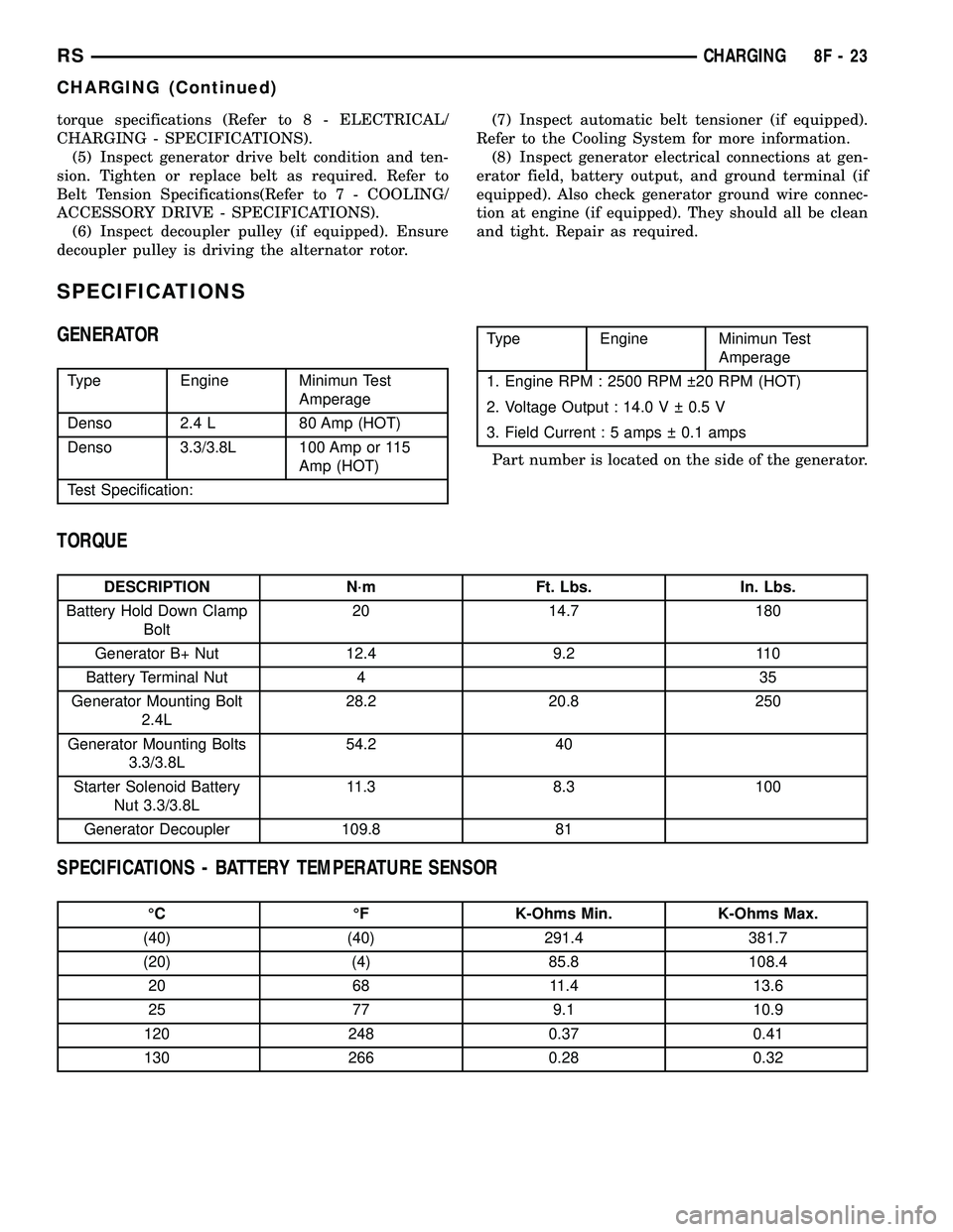
SPECIFICATIONS
GENERATOR
Type Engine Minimun Test
Amperage
Denso 2.4 L 80 Amp (HOT)
Denso 3.3/3.8L 100 Amp or 115
Amp (HOT)
Test Specification:
Type Engine Minimun Test
Amperage
1. Engine RPM : 2500 RPM 20 RPM (HOT)
2. Voltage Output : 14.0 V 0.5 V
3. Field Current : 5 amps 0.1 amps
Part number is located on the side of the generator.
TORQUE
DESCRIPTION N´m Ft. Lbs. In. Lbs.
Battery Hold Down Clamp
Bolt20 14.7 180
Generator B+ Nut 12.4 9.2 110
Battery Terminal Nut 4 35
Generator Mounting Bolt
2.4L28.2 20.8 250
Generator Mounting Bolts
3.3/3.8L54.2 40
Starter Solenoid Battery
Nut 3.3/3.8L11.3 8.3 100
Generator Decoupler 109.8 81
SPECIFICATIONS - BATTERY TEMPERATURE SENSOR
ÉC ÉF K-Ohms Min. K-Ohms Max.
(40) (40) 291.4 381.7
(20) (4) 85.8 108.4
20 68 11.4 13.6
25 77 9.1 10.9
120 248 0.37 0.41
130 266 0.28 0.32
RSCHARGING8F-23
CHARGING (Continued)
Page 334 of 2339
REMOVAL
(1) Release hood latch and open hood.
(2) Disconnect battery negative cable.
(3) Raise vehicle and support.
(4) Remove the right front lower splash shield.
(5) Remove accessory drive belt, refer to the Cool-
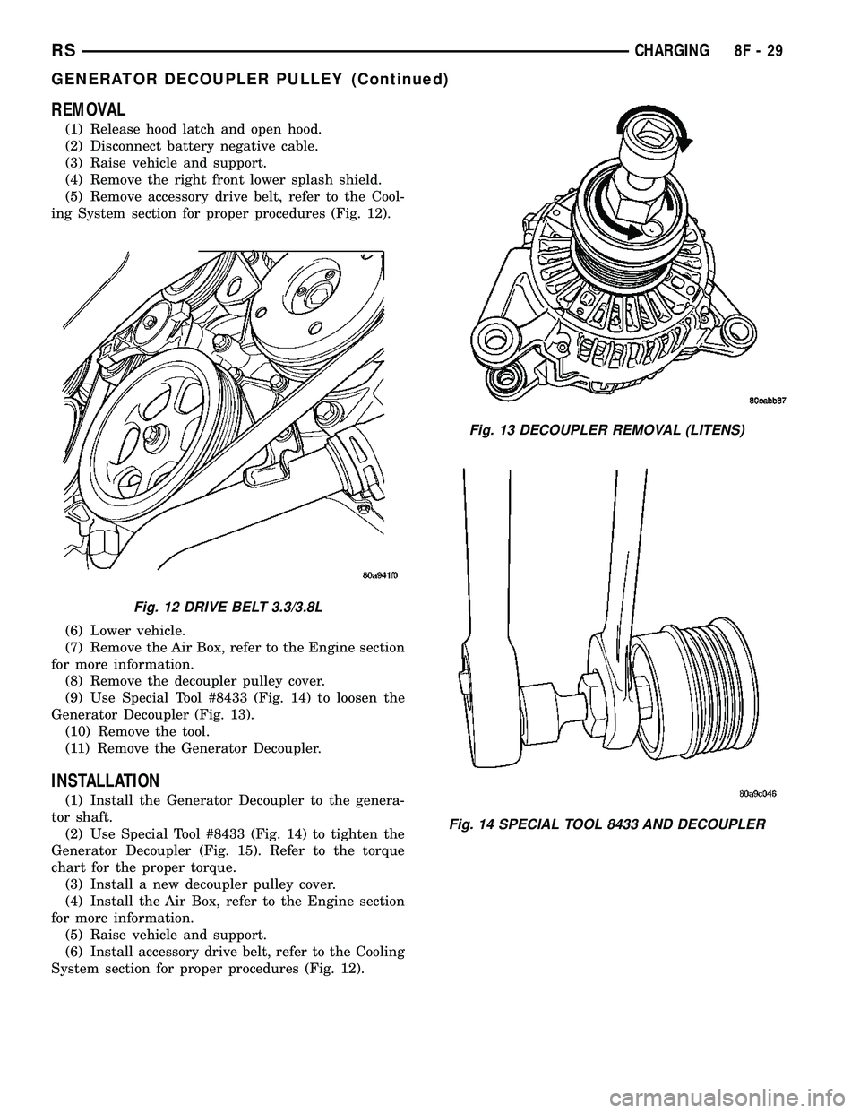
ing System section for proper procedures (Fig. 12).
(6) Lower vehicle.
(7) Remove the Air Box, refer to the Engine section
for more information.
(8) Remove the decoupler pulley cover.
(9) Use Special Tool #8433 (Fig. 14) to loosen the
Generator Decoupler (Fig. 13).
(10) Remove the tool.
(11) Remove the Generator Decoupler.
INSTALLATION
(1) Install the Generator Decoupler to the genera-
tor shaft.
(2) Use Special Tool #8433 (Fig. 14) to tighten the
Generator Decoupler (Fig. 15). Refer to the torque
chart for the proper torque.
(3) Install a new decoupler pulley cover.
(4) Install the Air Box, refer to the Engine section
for more information.
(5) Raise vehicle and support.
(6) Install accessory drive belt, refer to the Cooling
System section for proper procedures (Fig. 12).
Fig. 12 DRIVE BELT 3.3/3.8L
Fig. 13 DECOUPLER REMOVAL (LITENS)
Fig. 14 SPECIAL TOOL 8433 AND DECOUPLER
RSCHARGING8F-29
GENERATOR DECOUPLER PULLEY (Continued)
Page 336 of 2339
STARTING
TABLE OF CONTENTS
page page
STARTING
DESCRIPTION.........................31
OPERATION...........................31
DIAGNOSIS AND TESTING
DIAGNOSIS AND TESTING - STARTING
SYSTEM TEST.......................31
DIAGNOSIS AND TESTING - CONTROL
CIRCUIT TEST........................33
DIAGNOSIS AND TESTING - FEED CIRCUIT
RESISTANCE TEST....................35
DIAGNOSIS AND TESTING - FEED CIRCUIT
TEST...............................36SPECIFICATIONS
Torques.............................36
STARTER ...........................37
STARTER MOTOR
REMOVAL
REMOVAL - 2.4L......................37
REMOVAL - 3.3/3.8L...................38
REMOVAL - 2.5L......................38
INSTALLATION
INSTALLATION - 2.4L..................39
INSTALLATION - 3.3/3.8L................39
INSTALLATION - 2.5L..................39
STARTING
DESCRIPTION
The starting system consists of:
²Starter relay
²Starter motor (including an integral starter sole-
noid)
Other components to be considered as part of start-
ing system are:
²Battery
²Battery cables
²Ignition switch and key lock cylinder
²Clutch pedal position switch (manual transmis-
sion)
²Park/neutral position switch (automatic trans-
mission)
²Wire harnesses and connections.
The Battery, Starting, and Charging systems oper-
ate in conjunction with one another, and must be
tested as a complete system. For correct operation of
starting/charging systems, all components used in
these 3 systems must perform within specifications.
When attempting to diagnose any of these systems, it
is important that you keep their interdependency in
mind.
The diagnostic procedures used in each of these
groups include the most basic conventional diagnostic
methods, to the more sophisticated On-Board Diag-
nostics (OBD) built into the Powertrain Control Mod-
ule (PCM). Use of an induction-type milliampere
ammeter, volt/ohmmeter, battery charger, carbon pile
rheostat (load tester), and 12-volt test lamp may be
required.
OPERATION
These components form two separate circuits. A
high amperage circuit that feeds the starter motor up
to 300+ amps, and a control circuit that operates on
less than 20 amps.
The PCM controls a double start over-ride safety
that does not allow the starter to be engaged if the
engine is already running.
DIAGNOSIS AND TESTING
DIAGNOSIS AND TESTING - STARTING
SYSTEM TEST
For circuit descriptions and diagrams, refer to the
Wiring Diagrams.
WARNING: ON VEHICLES EQUIPPED WITH AIR-
BAGS, REFER TO THE PASSIVE RESTRAINT SYS-
TEMS BEFORE ATTEMPTING STEERING WHEEL,
STEERING COLUMN, OR INSTRUMENT PANEL
COMPONENT DIAGNOSIS OR SERVICE. FAILURE
TO TAKE THE PROPER PRECAUTIONS COULD
RESULT IN ACCIDENTAL AIRBAG DEPLOYMENT
AND POSSIBLE PERSONAL INJURY.
INSPECTION
Before removing any unit from the starting system
for repair or diagnosis, perform the following inspec-
tions:
²Battery- Visually inspect the battery for indi-
cations of physical damage and loose or corroded
cable connections. Determine the state-of-charge and
cranking capacity of the battery. Charge or replace
RSSTARTING8F-31
Page 338 of 2339
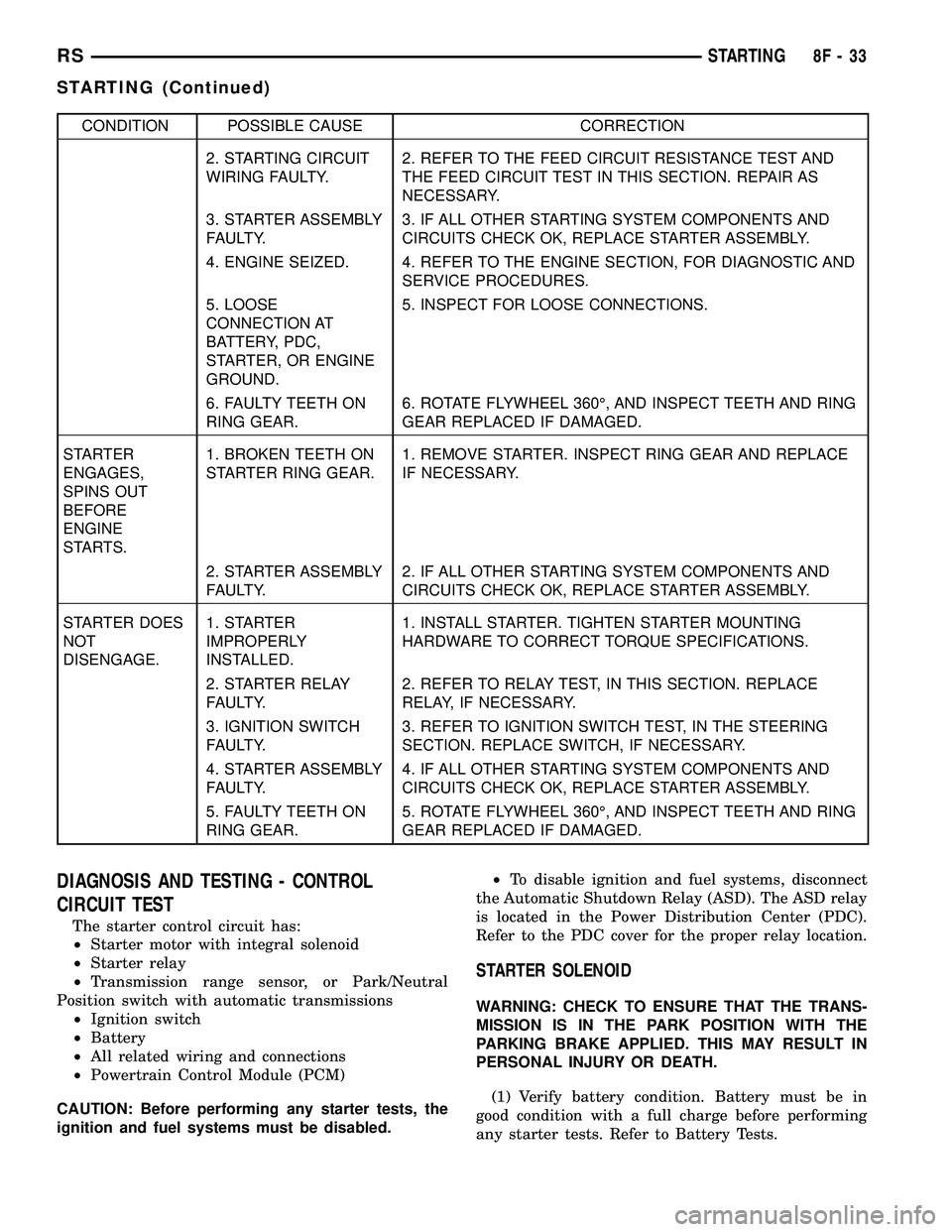
CONDITION POSSIBLE CAUSE CORRECTION
2. STARTING CIRCUIT
WIRING FAULTY.2. REFER TO THE FEED CIRCUIT RESISTANCE TEST AND
THE FEED CIRCUIT TEST IN THIS SECTION. REPAIR AS
NECESSARY.
3. STARTER ASSEMBLY
FAULTY.3. IF ALL OTHER STARTING SYSTEM COMPONENTS AND
CIRCUITS CHECK OK, REPLACE STARTER ASSEMBLY.
4. ENGINE SEIZED. 4. REFER TO THE ENGINE SECTION, FOR DIAGNOSTIC AND
SERVICE PROCEDURES.
5. LOOSE
CONNECTION AT
BATTERY, PDC,
STARTER, OR ENGINE
GROUND.5. INSPECT FOR LOOSE CONNECTIONS.
6. FAULTY TEETH ON
RING GEAR.6. ROTATE FLYWHEEL 360É, AND INSPECT TEETH AND RING
GEAR REPLACED IF DAMAGED.
STARTER
ENGAGES,
SPINS OUT
BEFORE
ENGINE
STARTS.1. BROKEN TEETH ON
STARTER RING GEAR.1. REMOVE STARTER. INSPECT RING GEAR AND REPLACE
IF NECESSARY.
2. STARTER ASSEMBLY
FAULTY.2. IF ALL OTHER STARTING SYSTEM COMPONENTS AND
CIRCUITS CHECK OK, REPLACE STARTER ASSEMBLY.
STARTER DOES
NOT
DISENGAGE.1. STARTER
IMPROPERLY
INSTALLED.1. INSTALL STARTER. TIGHTEN STARTER MOUNTING
HARDWARE TO CORRECT TORQUE SPECIFICATIONS.
2. STARTER RELAY
FAULTY.2. REFER TO RELAY TEST, IN THIS SECTION. REPLACE
RELAY, IF NECESSARY.
3. IGNITION SWITCH
FAULTY.3. REFER TO IGNITION SWITCH TEST, IN THE STEERING
SECTION. REPLACE SWITCH, IF NECESSARY.
4. STARTER ASSEMBLY
FAULTY.4. IF ALL OTHER STARTING SYSTEM COMPONENTS AND
CIRCUITS CHECK OK, REPLACE STARTER ASSEMBLY.
5. FAULTY TEETH ON
RING GEAR.5. ROTATE FLYWHEEL 360É, AND INSPECT TEETH AND RING
GEAR REPLACED IF DAMAGED.
DIAGNOSIS AND TESTING - CONTROL
CIRCUIT TEST
The starter control circuit has:
²Starter motor with integral solenoid
²Starter relay
²Transmission range sensor, or Park/Neutral
Position switch with automatic transmissions
²Ignition switch
²Battery
²All related wiring and connections
²Powertrain Control Module (PCM)
CAUTION: Before performing any starter tests, the
ignition and fuel systems must be disabled.²To disable ignition and fuel systems, disconnect
the Automatic Shutdown Relay (ASD). The ASD relay
is located in the Power Distribution Center (PDC).
Refer to the PDC cover for the proper relay location.
STARTER SOLENOID
WARNING: CHECK TO ENSURE THAT THE TRANS-
MISSION IS IN THE PARK POSITION WITH THE
PARKING BRAKE APPLIED. THIS MAY RESULT IN
PERSONAL INJURY OR DEATH.
(1) Verify battery condition. Battery must be in
good condition with a full charge before performing
any starter tests. Refer to Battery Tests.
RSSTARTING8F-33
STARTING (Continued)
Page 341 of 2339
the START position. If voltage reads above 0.2 volt,
correct poor starter to engine ground.
(a) Connect the positive voltmeter lead to the
battery positive terminal, and negative lead to bat-
tery cable terminal on starter solenoid. Rotate and
hold the ignition switch in the START position. If
voltage reads above 0.2 volt, correct poor contact at
battery cable to solenoid connection. If reading is
still above 0.2 volt after correcting poor contacts,
replace battery positive cable.
(b) If resistance tests do not detect feed circuit
failures, replace the starter motor.
DIAGNOSIS AND TESTING - FEED CIRCUIT
TEST
NOTE: The following results are based upon the
vehicle being at room temperature.
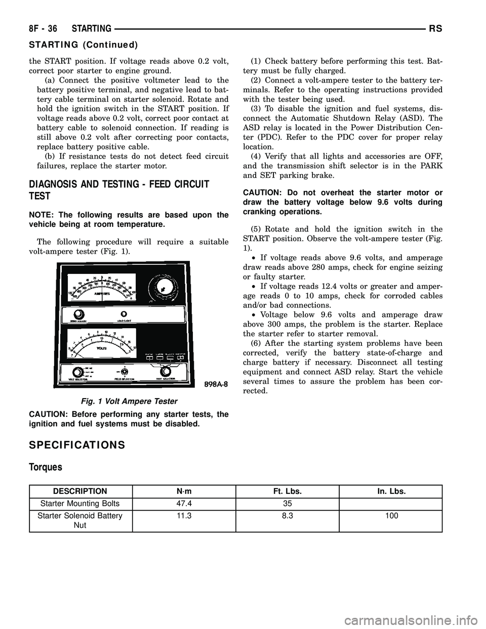
The following procedure will require a suitable
volt-ampere tester (Fig. 1).
CAUTION: Before performing any starter tests, the
ignition and fuel systems must be disabled.(1) Check battery before performing this test. Bat-
tery must be fully charged.
(2) Connect a volt-ampere tester to the battery ter-
minals. Refer to the operating instructions provided
with the tester being used.
(3) To disable the ignition and fuel systems, dis-
connect the Automatic Shutdown Relay (ASD). The
ASD relay is located in the Power Distribution Cen-
ter (PDC). Refer to the PDC cover for proper relay
location.
(4) Verify that all lights and accessories are OFF,
and the transmission shift selector is in the PARK
and SET parking brake.
CAUTION: Do not overheat the starter motor or
draw the battery voltage below 9.6 volts during
cranking operations.
(5) Rotate and hold the ignition switch in the
START position. Observe the volt-ampere tester (Fig.
1).
²If voltage reads above 9.6 volts, and amperage
draw reads above 280 amps, check for engine seizing
or faulty starter.
²If voltage reads 12.4 volts or greater and amper-
age reads 0 to 10 amps, check for corroded cables
and/or bad connections.
²Voltage below 9.6 volts and amperage draw
above 300 amps, the problem is the starter. Replace
the starter refer to starter removal.
(6) After the starting system problems have been
corrected, verify the battery state-of-charge and
charge battery if necessary. Disconnect all testing
equipment and connect ASD relay. Start the vehicle
several times to assure the problem has been cor-
rected.
SPECIFICATIONS
Torques
DESCRIPTION N´m Ft. Lbs. In. Lbs.
Starter Mounting Bolts 47.4 35
Starter Solenoid Battery
Nut11.3 8.3 100
Fig. 1 Volt Ampere Tester
8F - 36 STARTINGRS
STARTING (Continued)