3 row CHRYSLER VOYAGER 2005 Service Manual
[x] Cancel search | Manufacturer: CHRYSLER, Model Year: 2005, Model line: VOYAGER, Model: CHRYSLER VOYAGER 2005Pages: 2339, PDF Size: 59.69 MB
Page 17 of 2339
For best results, a refueling pattern that alternates
between E-85 and unleaded gasoline should be
avoided. When you do switch fuels, it is recom-
mended that
²you do not switch when the fuel gauge indicates
less than 1/4 full
²you do not add less than 5 gallons when refuel-
ing
²you operate the vehicle immediately after refuel-
ing for a period of at least 5 minutes
Observing these precautions will avoid possible
hard starting and/or significant deterioration in
driveability during warm up.
FFV STARTING
The characteristics of E-85 fuel make it unsuitable
for use when ambient temperatures fall below 0ÉF. In
the range of 0ÉF to 32ÉF, you may experience an
increase in the time it takes for your engine to start,
and a deterioration in driveability (sags and/or hesi-
tations) until the engine is fully warmed up.
Engine Operating on E-85 Fuel
If vehicle operates on E-85 fuel either full or part-
time, use only MopartFlexible Fuel 5W-30 engine oil
or an equivalent that meets DaimlerChrysler Stan-
dard MS-9214. Equivalent commercial Flexible Fuel
engine oils may be labeled as Multi-Fuel, Variable
Fuel, Flexible Fuel, etc. These engine oils may be
satisfactory if they meet the DaimlerChrysler Stan-
dard.
SAE 5W-30 engine oil is preferred for use in Flex-
ible Fuel engines.
CAUTION: If Flexible Fuel engine oil is not used
when using E-85 fuel, engine wear or damage may
result.
CRUISING RANGE
Because E-85 fuel contains less energy per gallon
than gasoline, you will experience an increase in fuel
consumption. You can expect your MPG and your
driving range to decrease by about 30% compared to
gasoline operation.
DESCRIPTION - AUTOMATIC/MANUAL
TRANSAXLE FLUID
NOTE: Refer to the maintenance schedules for the
recommended maintenance (fluid/filter change)
intervals for these transaxles.
NOTE: All transaxles have a common transmission
and differential sump. Filling the transaxle accom-
modates the differential as well.
TRANSMISSION FLUID
MopartATF+4 (Automatic Transmission Fluid) is
required in the 4XTE automatic and T850 manual
transaxles. Substitute fluids can induce transmission
problems and/or failure.
MopartATF+4 (Automatic Transmission Fluid)
when new is red in color. The ATF is dyed red so it
can be identified from other fluids used in the vehicle
such as engine oil or antifreeze. The red color is not
permanent and is not an indicator of fluid condition.
As the vehicle is driven, the ATF will begin to look
darker in color and may eventually become brown.
This is normal.ATF+4 also has a unique odor that
may change with age. Consequently,odor and color
cannot be used to indicate the fluid condition
or the need for a fluid change.
FLUID ADDITIVES
DaimlerChrysler strongly recommends against the
addition of any fluids to the transmission, other than
those automatic transmission fluids listed above.
Exceptions to this policy are the use of special dyes
to aid in detecting fluid leaks.
Various ªspecialº additives and supplements exist
that claim to improve shift feel and/or quality. These
additives and others also claim to improve converter
clutch operation and inhibit overheating, oxidation,
varnish, and sludge. These claims have not been sup-
ported to the satisfaction of DaimlerChrysler and
these additivesmust not be used.The use of trans-
mission ªsealersº should also be avoided, since they
may adversely affect the integrity of transmission
seals.
DESCRIPTION - FUEL REQUIREMENTS
Your engine is designed to meet all emissions reg-
ulations and provide excellent fuel economy and per-
formance when using high quality unleaded gasoline
having an octane rating of 87. The use of premium
gasoline is not recommended. The use of premium
gasoline will provide no benefit over high quality reg-
ular gasoline, and in some circumstances may result
in poorer performance.
Light spark knock at low engine speeds is not
harmful to your engine. However, continued heavy
spark knock at high speeds can cause damage and
immediate service is required. Engine damage result-
ing from operation with a heavy spark knock may
not be covered by the new vehicle warranty.
Poor quality gasoline can cause problems such as
hard starting, stalling and hesitations. If you experi-
ence these symptoms, try another brand of gasoline
before considering service for the vehicle.
Over 40 auto manufacturers world-wide have
issued and endorsed consistent gasoline specifications
(the Worldwide Fuel Charter, WWFC) to define fuel
0 - 4 LUBRICATION & MAINTENANCERS
FLUID TYPES (Continued)
Page 50 of 2339
INSPECTION - STEERING KNUCKLE
Inspect the knuckle for the following:
²Cracks or breaks
²Dents or damage
²Stress marks indicating a bend
The front suspension knuckle is not a repairable
component of the vehicles front suspension. If bent,
broken or damaged in any way, do not attempt to
straighten or repair the steering knuckle. It must be
replaced.
If inspection leads to the hub and bearing, (Refer
to 2 - SUSPENSION/FRONT/HUB / BEARING -
DIAGNOSIS AND TESTING)
INSTALLATION - STEERING KNUCKLE
(1) If the hub and bearing needs to be installed in
the knuckle, place the hub and bearing squarely into
the center hole of the steering knuckle aligning the
threaded mounting holes of the hub and bearing with
the mounting holes in the steering knuckle. Install
the four mounting bolts and tighten them to a torque
of 65 N´m (45 ft. lbs.).
CAUTION: Before installing the knuckle on the ball
joint stud, wipe the ball joint stud and knuckle con-
tact area free of any grease or debris, otherwisedamage to the knuckle can occur. Use a clean shop
cloth with MoparTBrake Parts Cleaner applied to it
for proper cleaning. Do not spray the stud directly.
(2) Place the knuckle on the ball joint stud.
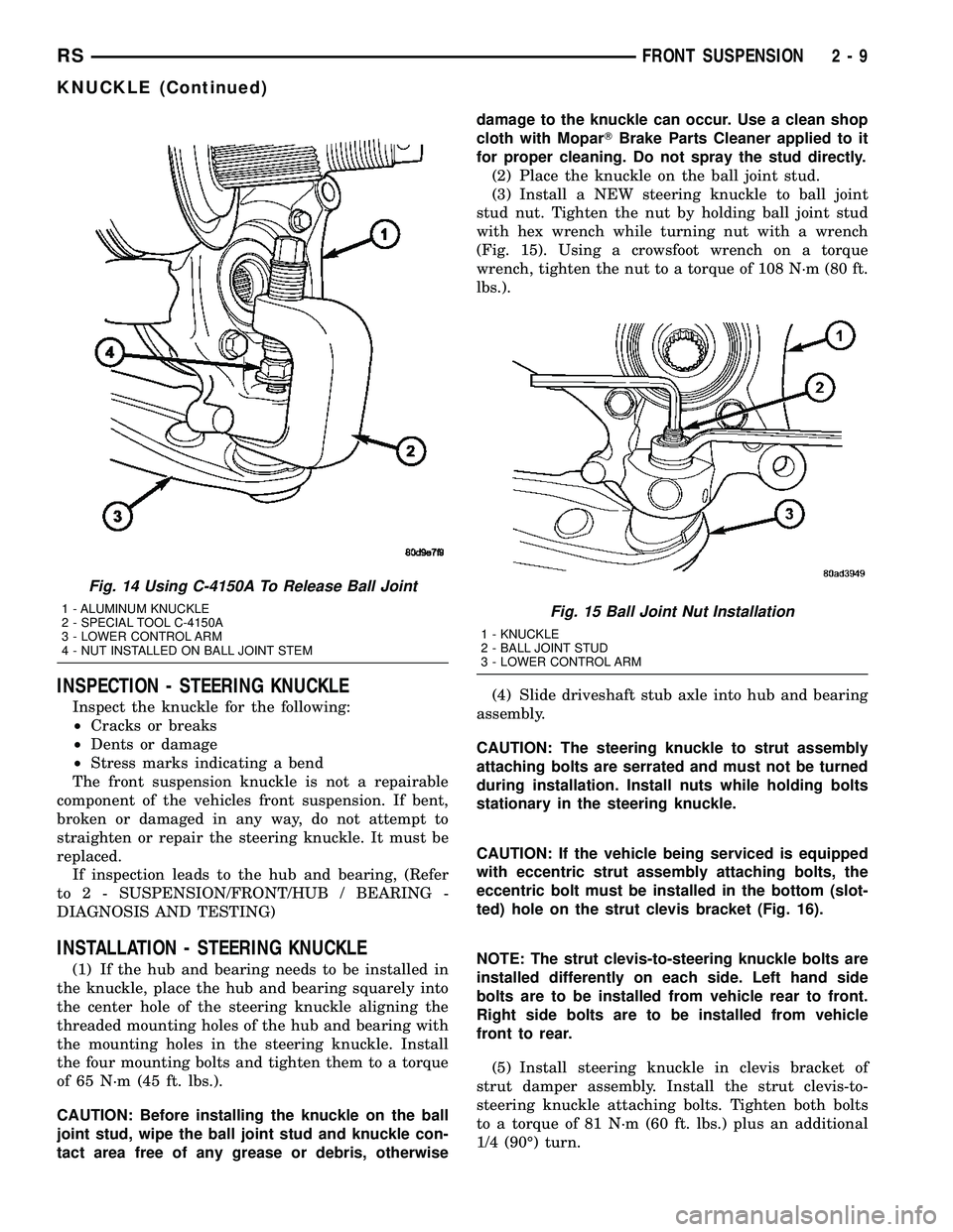
(3) Install a NEW steering knuckle to ball joint
stud nut. Tighten the nut by holding ball joint stud
with hex wrench while turning nut with a wrench
(Fig. 15). Using a crowsfoot wrench on a torque
wrench, tighten the nut to a torque of 108 N´m (80 ft.
lbs.).
(4) Slide driveshaft stub axle into hub and bearing
assembly.
CAUTION: The steering knuckle to strut assembly
attaching bolts are serrated and must not be turned
during installation. Install nuts while holding bolts
stationary in the steering knuckle.
CAUTION: If the vehicle being serviced is equipped
with eccentric strut assembly attaching bolts, the
eccentric bolt must be installed in the bottom (slot-
ted) hole on the strut clevis bracket (Fig. 16).
NOTE: The strut clevis-to-steering knuckle bolts are
installed differently on each side. Left hand side
bolts are to be installed from vehicle rear to front.
Right side bolts are to be installed from vehicle
front to rear.
(5) Install steering knuckle in clevis bracket of
strut damper assembly. Install the strut clevis-to-
steering knuckle attaching bolts. Tighten both bolts
to a torque of 81 N´m (60 ft. lbs.) plus an additional
1/4 (90É) turn.
Fig. 14 Using C-4150A To Release Ball Joint
1 - ALUMINUM KNUCKLE
2 - SPECIAL TOOL C-4150A
3 - LOWER CONTROL ARM
4 - NUT INSTALLED ON BALL JOINT STEMFig. 15 Ball Joint Nut Installation
1 - KNUCKLE
2 - BALL JOINT STUD
3 - LOWER CONTROL ARM
RSFRONT SUSPENSION2-9
KNUCKLE (Continued)
Page 66 of 2339
(12) Slowly release the tension from the coil spring
by backing off the compressor drive fully. As the ten-
sion is relieved, make sure the upper mount, pivot
bearing and upper seat are align properly. Remove
the clamp from the lower end of the coil spring and
strut. Push back the spring compressor upper and
lower hooks, then remove the strut assembly from
the spring compressor.
(13) Install strut assembly on the vehicle. (Refer to
2 - SUSPENSION/FRONT/STRUT - INSTALLA-
TION)
INSTALLATION - STRUT ASSEMBLY
CAUTION: Front strut coil springs are side-oriented.
When installing a strut assembly, make sure the
strut being installed has the correct coil spring for
that side of the vehicle. Springs on the left side of
the vehicle have a left-hand wind top-to-bottom
while springs on the right side have a right-hand
wind top-to-bottom (Fig. 49). Do not interchange the
two sides.
(1) Install strut assembly into strut tower, aligning
and installing the 3 studs on the upper strut mount
into the holes in shock tower. Install the 3 upper
strut mount attaching nut/washer assemblies (Fig.
43). Then using a crow foot. tighten the 3 attaching
nuts to a torque of 28 N´m (250 in. lbs.).
CAUTION: The steering knuckle to strut assembly
attaching bolts are serrated and must not be turned
during installation. Install nuts while holding bolts
stationary in the steering knuckles.
NOTE: The strut clevis-to-steering knuckle bolts are
installed differently on each side of the vehicle. Left
hand side bolts are to be installed from vehicle rear
to front. Right side bolts are to be installed from
vehicle front to rear.(2) Align strut assembly with steering knuckle.
Position arm of steering knuckle into strut assembly
clevis bracket. Align the strut assembly clevis
bracket mounting holes with the steering knuckle
mounting holes. Install the 2 strut assembly to steer-
ing knuckle attaching bolts (Fig. 42).If strut assem-
bly is attached to steering knuckle using a cam
bolt, the cam bolt must be installed in the lower
slotted hole on strut clevis bracket.Tighten the
strut clevis-to-steering knuckle attaching bolts to a
torque of 81 N´m (60 ft. lbs.) plus an additional 1/4
(90É) turn after specified torque is met.
(3) Install the stabilizer bar link mounting stud
through the bracket on the strut assembly (Fig. 41).
CAUTION: When installing the nut on the mounting
stud of the stabilizer bar link, do not allow the stud
to rotate in it's socket. Hold the stud from rotating
by placing an open-end wrench on the flat
machined into the stud (Fig. 41).
(4) Hand thread the nut on the end of the stabi-
lizer bar link stud. Hold the stud from turning by
placing an open-end wrench on the flat machined
into the link's mounting stud, then tighten the nut
while holding the wrench in place (Fig. 41). Tighten
the nut to a torque of 88 N´m (65 ft. lbs.).
(5) Install the hydraulic brake hose and speed sen-
sor cable routing brackets on the strut assembly
brackets (Fig. 40). Tighten the routing bracket
attaching bolts to a torque of 13 N´m (10 ft. lbs.).
(6) Install the wheel/tire assembly on the vehicle.
(7) Install and tighten the wheel mounting stud
nuts in proper sequence until all nuts are torqued to
half specification. Then repeat the tightening
sequence to the full specified torque of 135 N´m (100
ft. lbs.).
RSFRONT SUSPENSION2-25
STRUT (Continued)
Page 91 of 2339
THRUST ANGLE
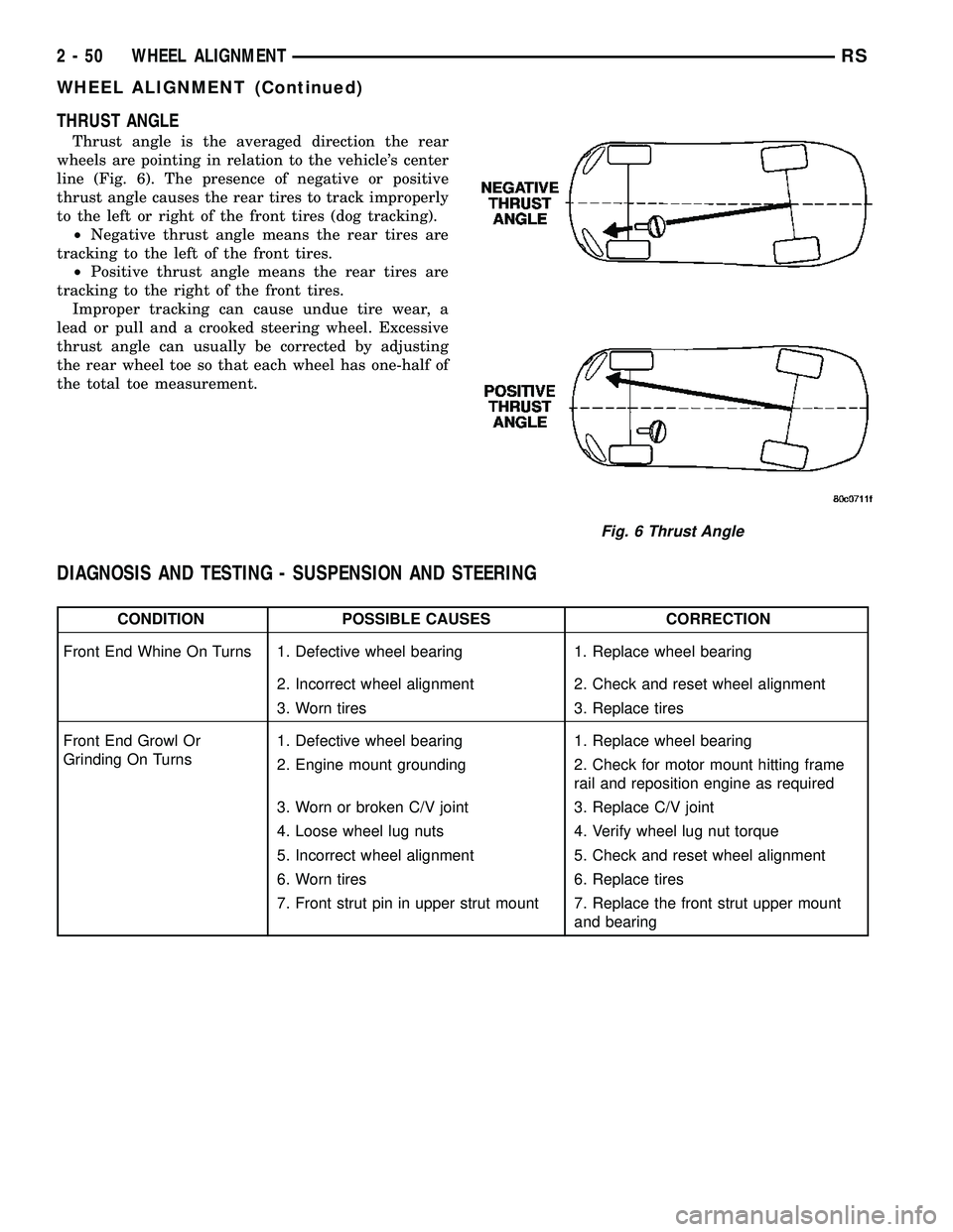
Thrust angle is the averaged direction the rear
wheels are pointing in relation to the vehicle's center
line (Fig. 6). The presence of negative or positive
thrust angle causes the rear tires to track improperly
to the left or right of the front tires (dog tracking).
²Negative thrust angle means the rear tires are
tracking to the left of the front tires.
²Positive thrust angle means the rear tires are
tracking to the right of the front tires.
Improper tracking can cause undue tire wear, a
lead or pull and a crooked steering wheel. Excessive
thrust angle can usually be corrected by adjusting
the rear wheel toe so that each wheel has one-half of
the total toe measurement.
DIAGNOSIS AND TESTING - SUSPENSION AND STEERING
CONDITION POSSIBLE CAUSES CORRECTION
Front End Whine On Turns 1. Defective wheel bearing 1. Replace wheel bearing
2. Incorrect wheel alignment 2. Check and reset wheel alignment
3. Worn tires 3. Replace tires
Front End Growl Or
Grinding On Turns1. Defective wheel bearing 1. Replace wheel bearing
2. Engine mount grounding 2. Check for motor mount hitting frame
rail and reposition engine as required
3. Worn or broken C/V joint 3. Replace C/V joint
4. Loose wheel lug nuts 4. Verify wheel lug nut torque
5. Incorrect wheel alignment 5. Check and reset wheel alignment
6. Worn tires 6. Replace tires
7. Front strut pin in upper strut mount 7. Replace the front strut upper mount
and bearing
Fig. 6 Thrust Angle
2 - 50 WHEEL ALIGNMENTRS
WHEEL ALIGNMENT (Continued)
Page 92 of 2339
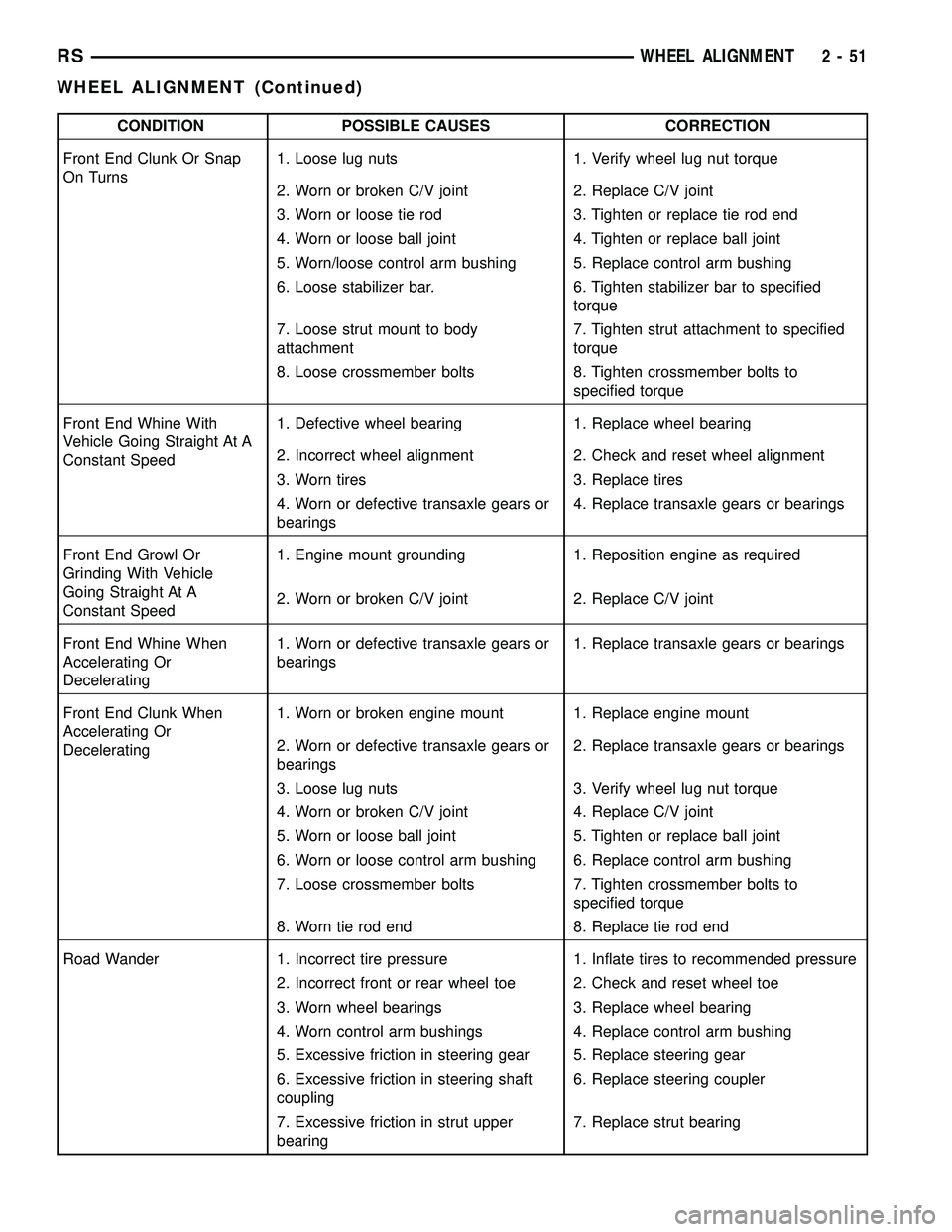
CONDITION POSSIBLE CAUSES CORRECTION
Front End Clunk Or Snap
On Turns1. Loose lug nuts 1. Verify wheel lug nut torque
2. Worn or broken C/V joint 2. Replace C/V joint
3. Worn or loose tie rod 3. Tighten or replace tie rod end
4. Worn or loose ball joint 4. Tighten or replace ball joint
5. Worn/loose control arm bushing 5. Replace control arm bushing
6. Loose stabilizer bar. 6. Tighten stabilizer bar to specified
torque
7. Loose strut mount to body
attachment7. Tighten strut attachment to specified
torque
8. Loose crossmember bolts 8. Tighten crossmember bolts to
specified torque
Front End Whine With
Vehicle Going Straight At A
Constant Speed1. Defective wheel bearing 1. Replace wheel bearing
2. Incorrect wheel alignment 2. Check and reset wheel alignment
3. Worn tires 3. Replace tires
4. Worn or defective transaxle gears or
bearings4. Replace transaxle gears or bearings
Front End Growl Or
Grinding With Vehicle
Going Straight At A
Constant Speed1. Engine mount grounding 1. Reposition engine as required
2. Worn or broken C/V joint 2. Replace C/V joint
Front End Whine When
Accelerating Or
Decelerating1. Worn or defective transaxle gears or
bearings1. Replace transaxle gears or bearings
Front End Clunk When
Accelerating Or
Decelerating1. Worn or broken engine mount 1. Replace engine mount
2. Worn or defective transaxle gears or
bearings2. Replace transaxle gears or bearings
3. Loose lug nuts 3. Verify wheel lug nut torque
4. Worn or broken C/V joint 4. Replace C/V joint
5. Worn or loose ball joint 5. Tighten or replace ball joint
6. Worn or loose control arm bushing 6. Replace control arm bushing
7. Loose crossmember bolts 7. Tighten crossmember bolts to
specified torque
8. Worn tie rod end 8. Replace tie rod end
Road Wander 1. Incorrect tire pressure 1. Inflate tires to recommended pressure
2. Incorrect front or rear wheel toe 2. Check and reset wheel toe
3. Worn wheel bearings 3. Replace wheel bearing
4. Worn control arm bushings 4. Replace control arm bushing
5. Excessive friction in steering gear 5. Replace steering gear
6. Excessive friction in steering shaft
coupling6. Replace steering coupler
7. Excessive friction in strut upper
bearing7. Replace strut bearing
RSWHEEL ALIGNMENT2-51
WHEEL ALIGNMENT (Continued)
Page 254 of 2339
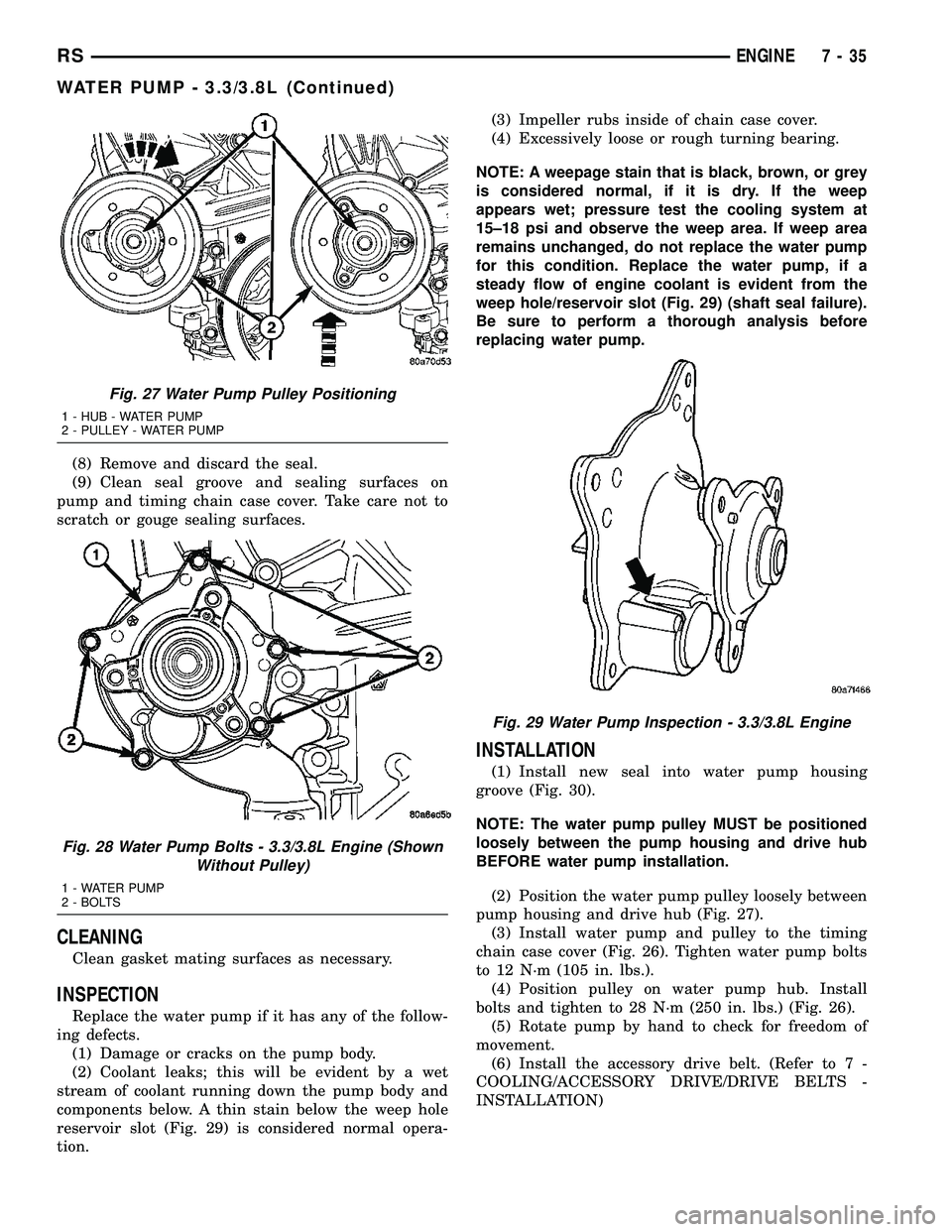
(8) Remove and discard the seal.
(9) Clean seal groove and sealing surfaces on
pump and timing chain case cover. Take care not to
scratch or gouge sealing surfaces.
CLEANING
Clean gasket mating surfaces as necessary.
INSPECTION
Replace the water pump if it has any of the follow-
ing defects.
(1) Damage or cracks on the pump body.
(2) Coolant leaks; this will be evident by a wet
stream of coolant running down the pump body and
components below. A thin stain below the weep hole
reservoir slot (Fig. 29) is considered normal opera-
tion.(3) Impeller rubs inside of chain case cover.
(4) Excessively loose or rough turning bearing.
NOTE: A weepage stain that is black, brown, or grey
is considered normal, if it is dry. If the weep
appears wet; pressure test the cooling system at
15±18 psi and observe the weep area. If weep area
remains unchanged, do not replace the water pump
for this condition. Replace the water pump, if a
steady flow of engine coolant is evident from the
weep hole/reservoir slot (Fig. 29) (shaft seal failure).
Be sure to perform a thorough analysis before
replacing water pump.
INSTALLATION
(1) Install new seal into water pump housing
groove (Fig. 30).
NOTE: The water pump pulley MUST be positioned
loosely between the pump housing and drive hub
BEFORE water pump installation.
(2) Position the water pump pulley loosely between
pump housing and drive hub (Fig. 27).
(3) Install water pump and pulley to the timing
chain case cover (Fig. 26). Tighten water pump bolts
to 12 N´m (105 in. lbs.).
(4) Position pulley on water pump hub. Install
bolts and tighten to 28 N´m (250 in. lbs.) (Fig. 26).
(5) Rotate pump by hand to check for freedom of
movement.
(6) Install the accessory drive belt. (Refer to 7 -
COOLING/ACCESSORY DRIVE/DRIVE BELTS -
INSTALLATION)
Fig. 27 Water Pump Pulley Positioning
1 - HUB - WATER PUMP
2 - PULLEY - WATER PUMP
Fig. 28 Water Pump Bolts - 3.3/3.8L Engine (Shown
Without Pulley)
1 - WATER PUMP
2 - BOLTS
Fig. 29 Water Pump Inspection - 3.3/3.8L Engine
RSENGINE7-35
WATER PUMP - 3.3/3.8L (Continued)
Page 320 of 2339
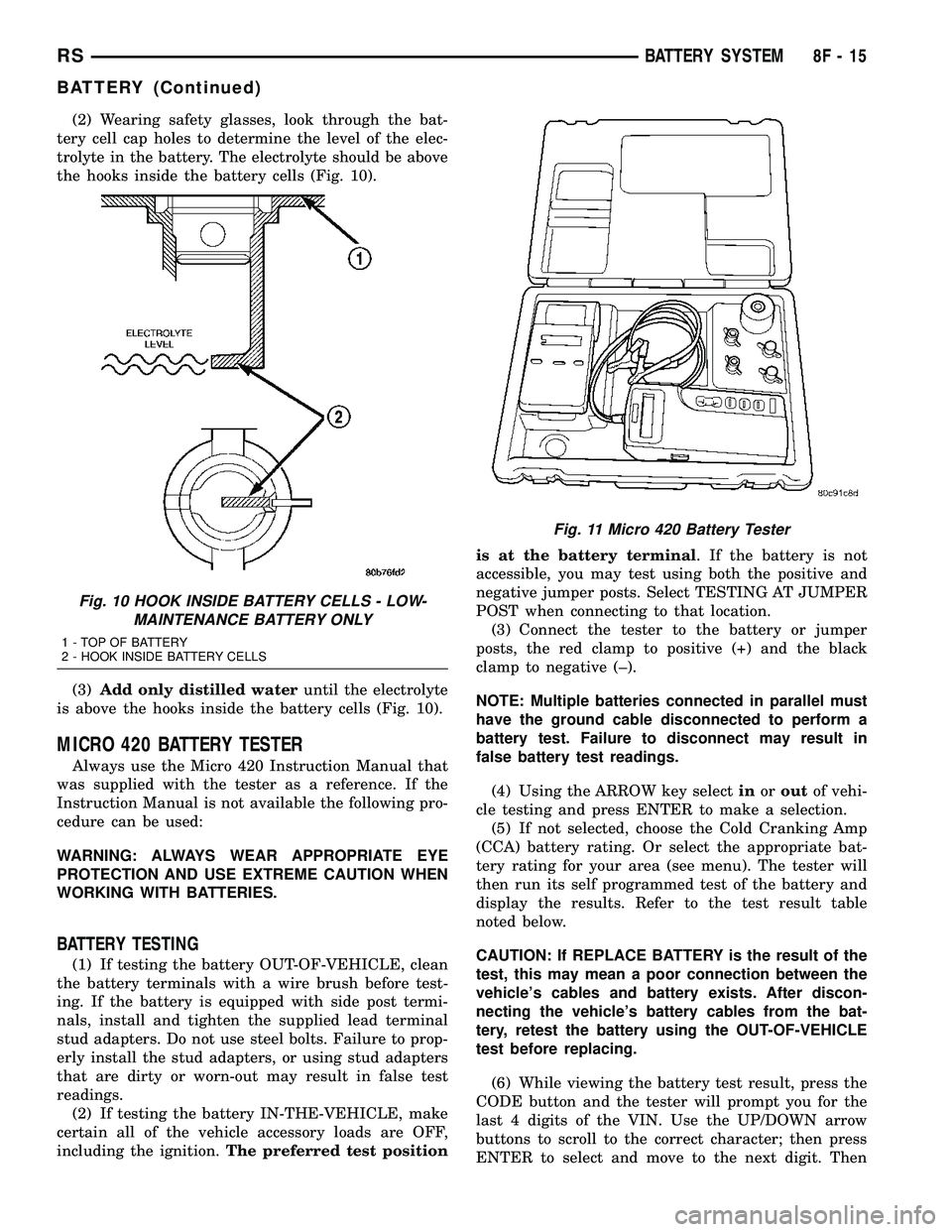
(2) Wearing safety glasses, look through the bat-
tery cell cap holes to determine the level of the elec-
trolyte in the battery. The electrolyte should be above
the hooks inside the battery cells (Fig. 10).
(3)Add only distilled wateruntil the electrolyte
is above the hooks inside the battery cells (Fig. 10).
MICRO 420 BATTERY TESTER
Always use the Micro 420 Instruction Manual that
was supplied with the tester as a reference. If the
Instruction Manual is not available the following pro-
cedure can be used:
WARNING: ALWAYS WEAR APPROPRIATE EYE
PROTECTION AND USE EXTREME CAUTION WHEN
WORKING WITH BATTERIES.
BATTERY TESTING
(1) If testing the battery OUT-OF-VEHICLE, clean
the battery terminals with a wire brush before test-
ing. If the battery is equipped with side post termi-
nals, install and tighten the supplied lead terminal
stud adapters. Do not use steel bolts. Failure to prop-
erly install the stud adapters, or using stud adapters
that are dirty or worn-out may result in false test
readings.
(2) If testing the battery IN-THE-VEHICLE, make
certain all of the vehicle accessory loads are OFF,
including the ignition.The preferred test positionis at the battery terminal. If the battery is not
accessible, you may test using both the positive and
negative jumper posts. Select TESTING AT JUMPER
POST when connecting to that location.
(3) Connect the tester to the battery or jumper
posts, the red clamp to positive (+) and the black
clamp to negative (±).
NOTE: Multiple batteries connected in parallel must
have the ground cable disconnected to perform a
battery test. Failure to disconnect may result in
false battery test readings.
(4) Using the ARROW key selectinoroutof vehi-
cle testing and press ENTER to make a selection.
(5) If not selected, choose the Cold Cranking Amp
(CCA) battery rating. Or select the appropriate bat-
tery rating for your area (see menu). The tester will
then run its self programmed test of the battery and
display the results. Refer to the test result table
noted below.
CAUTION: If REPLACE BATTERY is the result of the
test, this may mean a poor connection between the
vehicle's cables and battery exists. After discon-
necting the vehicle's battery cables from the bat-
tery, retest the battery using the OUT-OF-VEHICLE
test before replacing.
(6) While viewing the battery test result, press the
CODE button and the tester will prompt you for the
last 4 digits of the VIN. Use the UP/DOWN arrow
buttons to scroll to the correct character; then press
ENTER to select and move to the next digit. Then
Fig. 10 HOOK INSIDE BATTERY CELLS - LOW-
MAINTENANCE BATTERY ONLY
1 - TOP OF BATTERY
2 - HOOK INSIDE BATTERY CELLS
Fig. 11 Micro 420 Battery Tester
RSBATTERY SYSTEM8F-15
BATTERY (Continued)
Page 367 of 2339
CAMSHAFT POSITION
SENSOR
DESCRIPTION
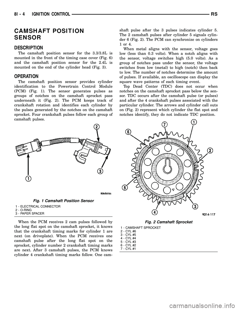
The camshaft position sensor for the 3.3/3.8L is
mounted in the front of the timing case cover (Fig. 6)
and the camshaft position sensor for the 2.4L is
mounted on the end of the cylinder head (Fig. 3).
OPERATION
The camshaft position sensor provides cylinder
identification to the Powertrain Control Module
(PCM) (Fig. 1). The sensor generates pulses as
groups of notches on the camshaft sprocket pass
underneath it (Fig. 2). The PCM keeps track of
crankshaft rotation and identifies each cylinder by
the pulses generated by the notches on the camshaft
sprocket. Four crankshaft pulses follow each group of
camshaft pulses.
When the PCM receives 2 cam pulses followed by
the long flat spot on the camshaft sprocket, it knows
that the crankshaft timing marks for cylinder 1 are
next (on driveplate). When the PCM receives one
camshaft pulse after the long flat spot on the
sprocket, cylinder number 2 crankshaft timing marks
are next. After 3 camshaft pulses, the PCM knows
cylinder 4 crankshaft timing marks follow. One cam-shaft pulse after the 3 pulses indicates cylinder 5.
The 2 camshaft pulses after cylinder 5 signals cylin-
der 6 (Fig. 2). The PCM can synchronize on cylinders
1or4.
When metal aligns with the sensor, voltage goes
low (less than 0.3 volts). When a notch aligns with
the sensor, voltage switches high (5.0 volts). As a
group of notches pass under the sensor, the voltage
switches from low (metal) to high (notch) then back
to low. The number of notches determine the amount
of pulses. If available, an oscilloscope can display the
square wave patterns of each timing event.
Top Dead Center (TDC) does not occur when
notches on the camshaft sprocket pass below the sen-
sor. TDC occurs after the camshaft pulse (or pulses)
and after the 4 crankshaft pulses associated with the
particular cylinder. The arrows and cylinder call outs
on (Fig. 2) represent which cylinder the flat spot and
notches identify, they do not indicate TDC position.
Fig. 1 Camshaft Position Sensor
1 - ELECTRICAL CONNECTOR
2 - O-RING
3 - PAPER SPACER
Fig. 2 Camshaft Sprocket
1 - CAMSHAFT SPROCKET
2 - CYL #6
3 - CYL #5
4 - CYL #4
5 - CYL #3
6 - CYL #2
7 - CYL #1
8I - 4 IGNITION CONTROLRS
Page 371 of 2339
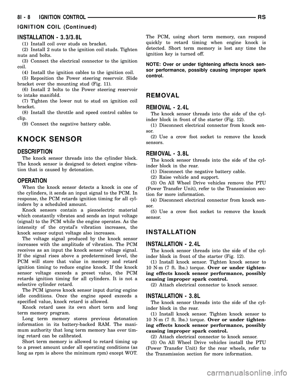
INSTALLATION - 3.3/3.8L
(1) Install coil over studs on bracket.
(2) Install 2 nuts to the ignition coil studs. Tighten
nuts and bolts.
(3) Connect the electrical connector to the ignition
coil.
(4) Install the ignition cables to the ignition coil.
(5) Reposition the Power steering reservoir. Slide
bracket over the mounting stud (Fig. 11).
(6) Install 2 bolts to the Power steering reservoir
to intake manifold.
(7) Tighten the lower nut to stud on ignition coil
bracket.
(8) Install the throttle and speed control cables to
clip.
(9) Connect the negative battery cable.
KNOCK SENSOR
DESCRIPTION
The knock sensor threads into the cylinder block.
The knock sensor is designed to detect engine vibra-
tion that is caused by detonation.
OPERATION
When the knock sensor detects a knock in one of
the cylinders, it sends an input signal to the PCM. In
response, the PCM retards ignition timing for all cyl-
inders by a scheduled amount.
Knock sensors contain a piezoelectric material
which constantly vibrates and sends an input voltage
(signal) to the PCM while the engine operates. As the
intensity of the crystal's vibration increases, the
knock sensor output voltage also increases.
The voltage signal produced by the knock sensor
increases with the amplitude of vibration. The PCM
receives as an input the knock sensor voltage signal.
If the signal rises above a predetermined level, the
PCM will store that value in memory and retard
ignition timing to reduce engine knock. If the knock
sensor voltage exceeds a preset value, the PCM
retards ignition timing for all cylinders. It is not a
selective cylinder retard.
The PCM ignores knock sensor input during engine
idle conditions. Once the engine speed exceeds a
specified value, knock retard is allowed.
Knock retard uses its own short term and long
term memory program.
Long term memory stores previous detonation
information in its battery-backed RAM. The maxi-
mum authority that long term memory has over tim-
ing retard can be calibrated.
Short term memory is allowed to retard timing up
to a preset amount under all operating conditions (as
long as rpm is above the minimum rpm) except WOT.The PCM, using short term memory, can respond
quickly to retard timing when engine knock is
detected. Short term memory is lost any time the
ignition key is turned off.
NOTE: Over or under tightening affects knock sen-
sor performance, possibly causing improper spark
control.
REMOVAL
REMOVAL - 2.4L
The knock sensor threads into the side of the cyl-
inder block in front of the starter (Fig. 12).
(1) Disconnect electrical connector from knock sen-
sor.
(2) Use a crow foot socket to remove the knock
sensors.
REMOVAL - 3.8L
The knock sensor threads into the side of the cyl-
inder block in the rear.
(1) Disconnect the negative battery cable.
(2) Raise vehicle and support.
(3) On All Wheel Drive vehicles remove the PTU
(Power Transfer Unit), refer to the Transmission sec-
tion for more information.
(4) Disconnect electrical connector from knock sen-
sor.
(5) Use a crow foot socket to remove the knock
sensor.
INSTALLATION
INSTALLATION - 2.4L
The knock sensor threads into the side of the cyl-
inder block in front of the starter (Fig. 12).
(1) Install knock sensor. Tighten knock sensor to
10 N´m (7 ft. lbs.) torque.Over or under tighten-
ing effects knock sensor performance, possibly
causing improper spark control.
(2) Attach electrical connector to knock sensor.
INSTALLATION - 3.8L
The knock sensor threads into the side of the cyl-
inder block in the rear.
(1) Install knock sensor. Tighten knock sensor to
10 N´m (7 ft. lbs.) torque.Over or under tighten-
ing effects knock sensor performance, possibly
causing improper spark control.
(2) Attach electrical connector to knock sensor.
(3) On All Wheel Drive vehicles install the PTU
(Power Transfer Unit) for the rear wheels, refer to
the Transmission section for more information.
8I - 8 IGNITION CONTROLRS
IGNITION COIL (Continued)
Page 488 of 2339
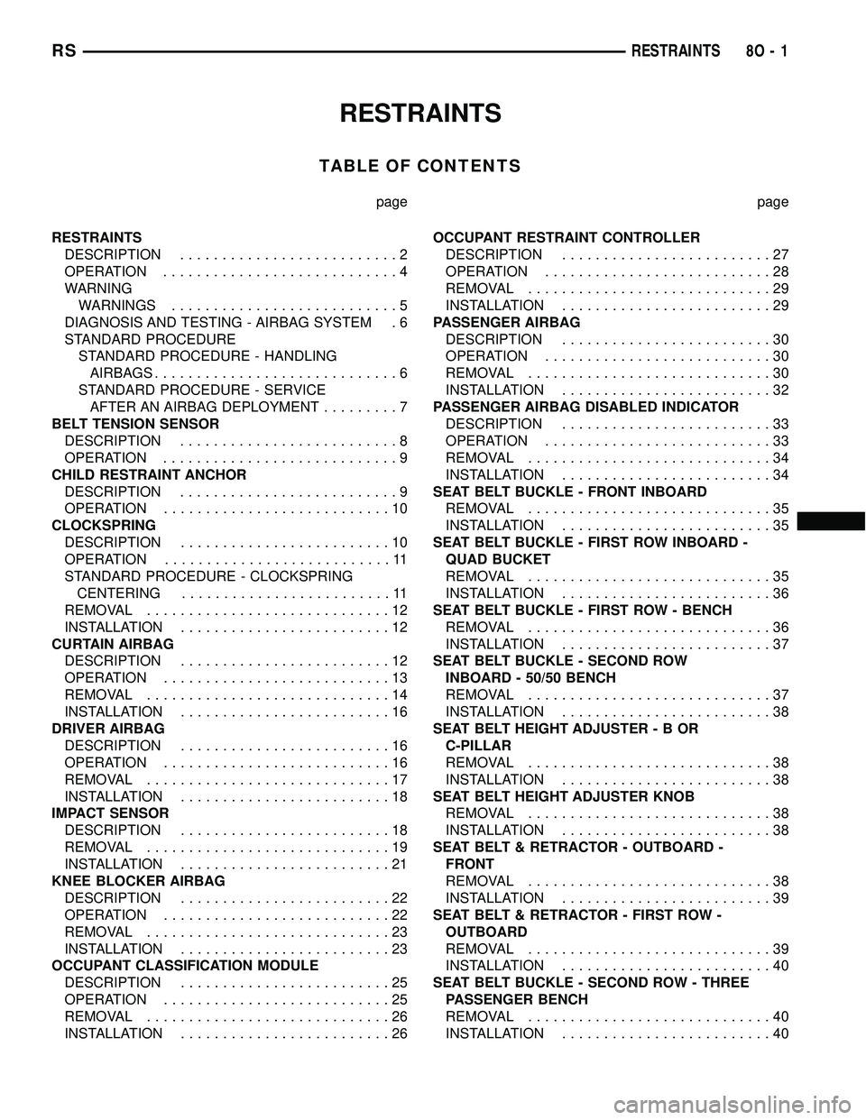
RESTRAINTS
TABLE OF CONTENTS
page page
RESTRAINTS
DESCRIPTION..........................2
OPERATION............................4
WARNING
WARNINGS...........................5
DIAGNOSIS AND TESTING - AIRBAG SYSTEM . 6
STANDARD PROCEDURE
STANDARD PROCEDURE - HANDLING
AIRBAGS.............................6
STANDARD PROCEDURE - SERVICE
AFTER AN AIRBAG DEPLOYMENT.........7
BELT TENSION SENSOR
DESCRIPTION..........................8
OPERATION............................9
CHILD RESTRAINT ANCHOR
DESCRIPTION..........................9
OPERATION...........................10
CLOCKSPRING
DESCRIPTION.........................10
OPERATION...........................11
STANDARD PROCEDURE - CLOCKSPRING
CENTERING.........................11
REMOVAL.............................12
INSTALLATION.........................12
CURTAIN AIRBAG
DESCRIPTION.........................12
OPERATION...........................13
REMOVAL.............................14
INSTALLATION.........................16
DRIVER AIRBAG
DESCRIPTION.........................16
OPERATION...........................16
REMOVAL.............................17
INSTALLATION.........................18
IMPACT SENSOR
DESCRIPTION.........................18
REMOVAL.............................19
INSTALLATION.........................21
KNEE BLOCKER AIRBAG
DESCRIPTION.........................22
OPERATION...........................22
REMOVAL.............................23
INSTALLATION.........................23
OCCUPANT CLASSIFICATION MODULE
DESCRIPTION.........................25
OPERATION...........................25
REMOVAL.............................26
INSTALLATION.........................26OCCUPANT RESTRAINT CONTROLLER
DESCRIPTION.........................27
OPERATION...........................28
REMOVAL.............................29
INSTALLATION.........................29
PASSENGER AIRBAG
DESCRIPTION.........................30
OPERATION...........................30
REMOVAL.............................30
INSTALLATION.........................32
PASSENGER AIRBAG DISABLED INDICATOR
DESCRIPTION.........................33
OPERATION...........................33
REMOVAL.............................34
INSTALLATION.........................34
SEAT BELT BUCKLE - FRONT INBOARD
REMOVAL.............................35
INSTALLATION.........................35
SEAT BELT BUCKLE - FIRST ROW INBOARD -
QUAD BUCKET
REMOVAL.............................35
INSTALLATION.........................36
SEAT BELT BUCKLE - FIRST ROW - BENCH
REMOVAL.............................36
INSTALLATION.........................37
SEAT BELT BUCKLE - SECOND ROW
INBOARD - 50/50 BENCH
REMOVAL.............................37
INSTALLATION.........................38
SEAT BELT HEIGHT ADJUSTER-BOR
C-PILLAR
REMOVAL.............................38
INSTALLATION.........................38
SEAT BELT HEIGHT ADJUSTER KNOB
REMOVAL.............................38
INSTALLATION.........................38
SEAT BELT & RETRACTOR - OUTBOARD -
FRONT
REMOVAL.............................38
INSTALLATION.........................39
SEAT BELT & RETRACTOR - FIRST ROW -
OUTBOARD
REMOVAL.............................39
INSTALLATION.........................40
SEAT BELT BUCKLE - SECOND ROW - THREE
PASSENGER BENCH
REMOVAL.............................40
INSTALLATION.........................40
RSRESTRAINTS8O-1