power steering CHRYSLER VOYAGER 2020 Owners Manual
[x] Cancel search | Manufacturer: CHRYSLER, Model Year: 2020, Model line: VOYAGER, Model: CHRYSLER VOYAGER 2020Pages: 516, PDF Size: 28.69 MB
Page 4 of 516
2
INTRODUCTION
HOW TO USE THIS MANUAL ................................10
Essential Information .................................. 10
Symbols ........................................................ 10
WARNINGS AND CAUTIONS ...............................10
VEHICLE MODIFICATIONS/ALTERATIONS ........11
GETTING TO KNOW YOUR VEHICLE
VEHICLE USER GUIDE — IF EQUIPPED ...............12
KEYS ......................................................................13
Key Fob......................................................... 13
IGNITION SWITCH .................................................18
Keyless Enter-N-Go — Ignition ..................... 18
REMOTE STARTING SYSTEM — IF EQUIPPED ...19
How To Use Remote Start ........................... 20
Remote Start Cancel Message —
If Equipped ................................................... 20 To Enter Remote Start Mode ...................... 21
To Exit Remote Start Mode Without Driving
The Vehicle .................................................. 21 To Exit Remote Start Mode And Drive The
Vehicle .......................................................... 21 Remote Start Comfort Systems —
If Equipped ................................................... 21 General Information .................................... 22 SENTRY KEY.......................................................... 22
Key Programming ....................................... 23
Replacement Keys....................................... 23
General Information .................................... 23
VEHICLE SECURITY ALARM — IF EQUIPPED ..... 24
To Arm The System ..................................... 24
To Disarm The System ................................ 24
Rearming Of The System............................. 25
DOORS ................................................................... 25
Manual Lock ................................................ 25
Central Lock/Unlock — If Equipped ............ 26
Unlock Doors Automatically On Exit — If
Equipped ...................................................... 27 Keyless Enter-N-Go — Passive Entry........... 27
Manual Sliding Side Door............................ 30
Power Sliding Side Door — If Equipped ...... 30
Hands-Free Sliding Doors — If Equipped.... 32
Child Locks ................................................... 32
DRIVER MEMORY SETTINGS — IF EQUIPPED .. 34
Programming The Memory Feature............ 34
Linking And Unlinking The Key Fob To
Memory ........................................................ 34 Memory Position Recall............................... 35 SEATS ....................................................................35
Manual Adjustment (Front Seats) — If
Equipped ...................................................... 35 Manual Adjustment (Rear Seats) ............... 37
Power Adjustment (Front Seats) —
If Equipped ................................................... 48 Power Adjustment (Rear Seats) —
If Equipped ................................................... 50 Heated Seats ............................................... 53
Ventilated Seats — If Equipped................... 54
Adjustable Armrest (Front Seats) —
If Equipped ................................................... 54 Plastic Grocery Bag Retainer Hooks .......... 54
HEAD RESTRAINTS ..............................................55
Head Restraints — Front Seats................... 55
Head Restraints — Second Row
Quad Seats .................................................. 56 Head Restraints — Second Row Bench...... 56
Head Restraints — Third Row ..................... 57
STEERING WHEEL.................................................58
Tilt/Telescoping Steering Column .............. 58
Heated Steering Wheel — If Equipped ....... 58
20_RU_OM_EN_US_t.book Page 2
Page 6 of 516
4
GETTING TO KNOW YOUR INSTRUMENT PANEL
INSTRUMENT CLUSTER..................................... 125
Instrument Cluster Descriptions ...............126
INSTRUMENT CLUSTER DISPLAY ................... 127
Instrument Cluster Display Location And
Controls ......................................................128 Oil Life Reset ..............................................129
Fuel And Oil Refresh Mode .......................129
KeySense Cluster Messages —
If Equipped .................................................130 Instrument Cluster Display Menu Items ..131
Battery Saver On/Battery Saver Mode
Message — Electrical Load Reduction
Actions — If Equipped ................................138 Instrument Cluster Display Programmable
Features Screen Setup.............................. 139
TRIP COMPUTER ............................................... 140
WARNING LIGHTS AND MESSAGES ............... 141
Red Warning Lights....................................141
Yellow Warning Lights ...............................144
Yellow Indicator Lights...............................147
Green Indicator Lights ...............................148
Blue Indicator Lights ..................................149White Indicator Lights................................149
ONBOARD DIAGNOSTIC SYSTEM — OBD II .... 150
Onboard Diagnostic System (OBD II)
Cybersecurity..............................................150
EMISSIONS INSPECTION AND MAINTENANCE
PROGRAMS ........................................................ 151
SAFETY
SAFETY FEATURES .............................................152 Anti-Lock Brake System (ABS) ................. 152
Electronic Brake Control (EBC) System ... 153
AUXILIARY DRIVING SYSTEMS.........................159 Blind Spot Monitoring (BSM) —
If Equipped ................................................. 159 Forward Collision Warning (FCW) With
Mitigation — If Equipped............................ 164 Tire Pressure Monitoring
System (TPMS) .......................................... 167
OCCUPANT RESTRAINT SYSTEMS .................. 171 Occupant Restraint Systems Features .... 171
Important Safety Precautions ................... 172
Seat Belt Systems ..................................... 172
Supplemental Restraint Systems (SRS)... 184
Child Restraints ......................................... 198
Transporting Pets ...................................... 215
SAFETY TIPS ....................................................... 216 Transporting Passengers .......................... 216Exhaust Gas .............................................. 216
Safety Checks You Should Make Inside
The Vehicle ................................................ 217 Periodic Safety Checks You Should Make
Outside The Vehicle ................................... 218
STARTING AND OPERATING
STARTING THE ENGINE .....................................219 Normal Starting.......................................... 219Cold Weather Operation (Below –22°F
Or −30°C) ................................................. 223 After Starting — Warming Up The
Engine ........................................................ 223 If Engine Fails To Start ............................. 223
To Turn Off The Engine Using ENGINE
START/STOP Button .................................. 223
ENGINE BLOCK HEATER — IF EQUIPPED ....... 224
ENGINE BREAK-IN RECOMMENDATIONS ...... 224
PARK BRAKE...................................................... 225 Electric Park Brake (EPB) ......................... 225
AUTOMATIC TRANSMISSION ........................... 228 Ignition Park Interlock ............................... 229Brake/Transmission Shift Interlock
System........................................................ 229 Nine-Speed Automatic Transmission ...... 230
Gear Ranges .............................................. 230
ACTIVE NOISE CANCELLATION ........................ 234
POWER STEERING............................................. 234
STOP/START SYSTEM — IF EQUIPPED ........... 235
Auto Stop/Start.......................................... 235
Possible Reasons The Engine Does Not
Autostop ..................................................... 235 To Start The Engine While In Auto
Stop/Start .................................................. 236 To Manually Turn Off The Stop/Start
System........................................................ 236 To Manually Turn On The Stop/Start
System........................................................ 237 System Malfunction................................... 237
20_RU_OM_EN_US_t.book Page 4
Page 23 of 516
GETTING TO KNOW YOUR VEHICLE21
Remote Start Cancelled — Too Cold
Remote Start Cancelled — Time Expired
Remote Start Disabled — Start Vehicle To
Reset
The message will stay active until the ignition is
placed in the ON/RUN position.
To Enter Remote Start Mode
If applicable, refer to the “Hybrid Supplement”
for additional information.
Push and release the Remote Start button on
the key fob twice within five seconds. The
vehicle doors will lock, the turn signals will flash
twice, and the horn will chirp twice. Then the
engine will start, and the vehicle will remain in
the Remote Start mode for a 15 minute cycle.
NOTE:
If an engine fault is present or fuel level is
low, the vehicle will start and then shut down
in 10 seconds.
The park lamps will turn on and remain on
during Remote Start mode.
For security, power window operation is
disabled when the vehicle is in the Remote
Start mode.
The engine can be started two consecutive
times (two 15 minute cycles) with the key
fob. However, the ignition must be placed in
the ON/RUN position before you can repeat
the start sequence for a third cycle.
To Exit Remote Start Mode Without Driving
The Vehicle
If applicable, refer to the “Hybrid Supplement”
for additional information.
Push and release the Remote Start button one
time or allow the remote start cycle to complete
the entire 15 minute cycle.
NOTE:
To avoid unintentional shutdowns, the system
will disable for two seconds after receiving a
valid Remote Start request.
To Exit Remote Start Mode And Drive The
Vehicle
Before the end of 15 minute cycle, push and
release the unlock button on the key fob to
unlock the doors, or unlock the vehicle using
Keyless Enter-N-Go — Passive Entry via the door handles, and disarm the vehicle security alarm
(if equipped). Then, prior to the end of the
15 minute cycle, push and release the START/
STOP ignition button.
NOTE:
For vehicles equipped with the Keyless
Enter-N-Go — Passive Entry feature, the
message “Remote Start Active — Push Start
Button” will display in the instrument cluster
display until you push the START/STOP ignition
button.
Remote Start Comfort Systems — If
Equipped
When Remote Start is activated, the Climate
Control, vented seats (if equipped) are also
activated in temperatures above 80°F
(26.7°C), and the optional heated seats, and
optional heated steering wheel in temperatures
below 40°F (4.4°C). These features will stay on
through the duration of Remote Start, or until
the ignition switch is placed in the ON/RUN
position.
2
20_RU_OM_EN_US_t.book Page 21
Page 36 of 516
34GETTING TO KNOW YOUR VEHICLE
DRIVER MEMORY SETTINGS — IF EQUIPPED
This feature allows the driver to save up to two
different memory profiles for easy recall
through a memory switch. Each memory profile
saves desired position settings for the following
features:
Driver’s seat
Easy Entry/Exit seat operation (on/off) (if
equipped)
Power steering wheel position (if equipped)
Side mirrors (if equipped)
A set of desired radio station presets
NOTE:
Your vehicle is equipped with two key fobs, each
can be linked to either memory position 1 or 2.
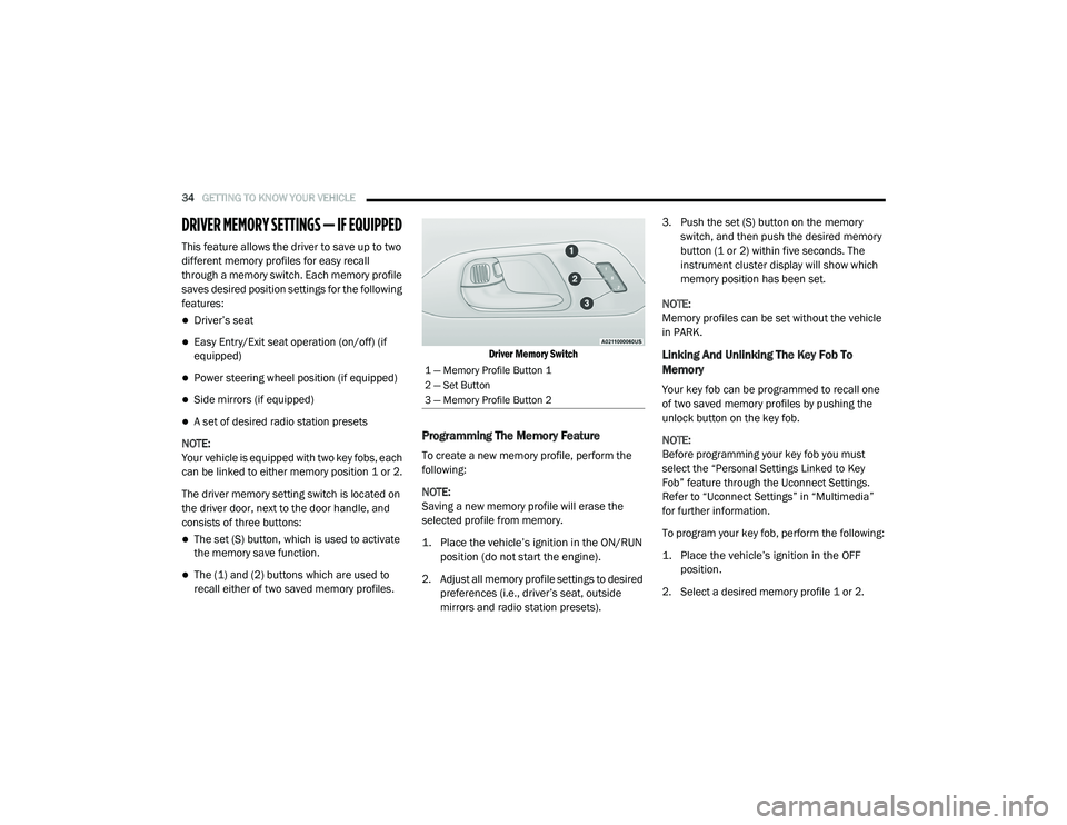
The driver memory setting switch is located on
the driver door, next to the door handle, and
consists of three buttons:
The set (S) button, which is used to activate
the memory save function.
The (1) and (2) buttons which are used to
recall either of two saved memory profiles.
Driver Memory Switch
Programming The Memory Feature
To create a new memory profile, perform the
following:
NOTE:
Saving a new memory profile will erase the
selected profile from memory.
1. Place the vehicle’s ignition in the ON/RUN
position (do not start the engine).
2. Adjust all memory profile settings to desired preferences (i.e., driver’s seat, outside
mirrors and radio station presets). 3. Push the set (S) button on the memory
switch, and then push the desired memory
button (1 or 2) within five seconds. The
instrument cluster display will show which
memory position has been set.
NOTE:
Memory profiles can be set without the vehicle
in PARK.
Linking And Unlinking The Key Fob To
Memory
Your key fob can be programmed to recall one
of two saved memory profiles by pushing the
unlock button on the key fob.
NOTE:
Before programming your key fob you must
select the “Personal Settings Linked to Key
Fob” feature through the Uconnect Settings.
Refer to “Uconnect Settings” in “Multimedia”
for further information.
To program your key fob, perform the following:
1. Place the vehicle’s ignition in the OFF position.
2. Select a desired memory profile 1 or 2.
1 — Memory Profile Button 1
2 — Set Button
3 — Memory Profile Button 2
20_RU_OM_EN_US_t.book Page 34
Page 60 of 516
58GETTING TO KNOW YOUR VEHICLE
Power Folding Third Row Head Restraints — If
Equipped
For improved visibility, the third row outboard
head restraints can be folded using the
Uconnect System.
Press the “Controls” button located on the
bottom of the Uconnect display.
Press the Head Restraint Fold button to
power fold the third row head restraints.
NOTE:
The head restraints can be folded downward
using the Head Restraint button or using the
manual release strap. The head restraints
must be raised manually when occupying the
third row.
Do not fold if there are passengers seated in
the third row seats.
STEERING WHEEL
Tilt/Telescoping Steering Column
This feature allows you to tilt the steering
column upward or downward. It also allows you
to lengthen or shorten the steering column. The tilt/telescoping lever is located left of the
steering wheel at the end of the steering
column.
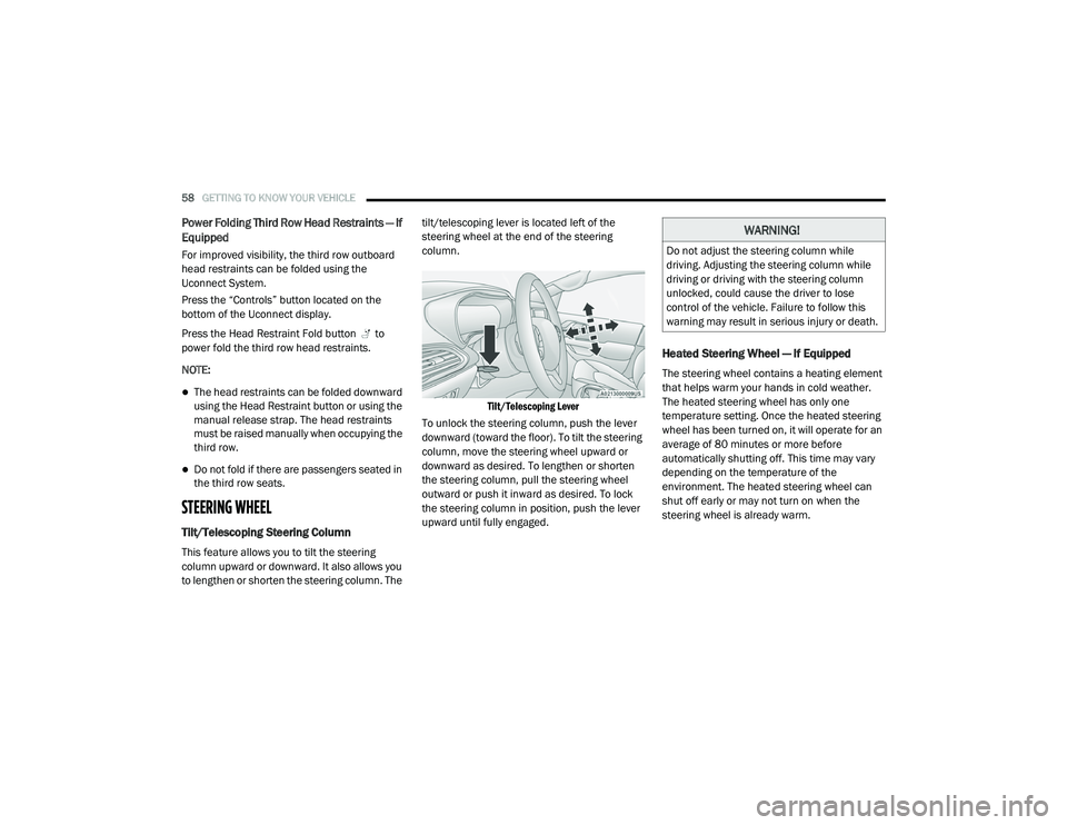
Tilt/Telescoping Lever
To unlock the steering column, push the lever
downward (toward the floor). To tilt the steering
column, move the steering wheel upward or
downward as desired. To lengthen or shorten
the steering column, pull the steering wheel
outward or push it inward as desired. To lock
the steering column in position, push the lever
upward until fully engaged.
Heated Steering Wheel — If Equipped
The steering wheel contains a heating element
that helps warm your hands in cold weather.
The heated steering wheel has only one
temperature setting. Once the heated steering
wheel has been turned on, it will operate for an
average of 80 minutes or more before
automatically shutting off. This time may vary
depending on the temperature of the
environment. The heated steering wheel can
shut off early or may not turn on when the
steering wheel is already warm.
WARNING!
Do not adjust the steering column while
driving. Adjusting the steering column while
driving or driving with the steering column
unlocked, could cause the driver to lose
control of the vehicle. Failure to follow this
warning may result in serious injury or death.
20_RU_OM_EN_US_t.book Page 58
Page 144 of 516
142GETTING TO KNOW YOUR INSTRUMENT PANEL
Vehicles equipped with the Anti-Lock Brake
System (ABS) are also equipped with Electronic
Brake Force Distribution (EBD). In the event of
an EBD failure, the Brake Warning Light will turn
on along with the ABS Light. Immediate repair to
the ABS system is required.
Operation of the Brake Warning Light can be
checked by turning the ignition switch from the
OFF position to the ON/RUN position. The light
should illuminate for approximately two
seconds. The light should then turn off unless
the parking brake is applied or a brake fault is
detected. If the light does not illuminate, have
the light inspected by an authorized dealer.
The light also will turn on when the parking
brake is applied with the ignition switch in the
ON/RUN position.
NOTE:
This light shows only that the parking brake is
applied. It does not show the degree of brake
application.Door Open Warning Light — If Equipped
This warning light will illuminate when
a door is ajar/open and not fully
closed. This indicator will reflect
which doors are open.
NOTE:
If the vehicle is moving, there will also be a
single chime.
Electric Power Steering Fault Warning Light
This warning light will turn on when
there's a fault with the Electric Power
Steering (EPS) system. Refer to
“Power Steering” in “Starting And
Operating” for further information.
Electronic Throttle Control (ETC) Warning
Light
This warning light will illuminate to
indicate a problem with the Electronic
Throttle Control (ETC) system. If a
problem is detected while the vehicle
is running, the light will either stay on or flash
depending on the nature of the problem. Cycle
the ignition when the vehicle is safely and
completely stopped and the transmission is
placed in the PARK (P) position. The light should
turn off. If the light remains on with the vehicle
running, your vehicle will usually be drivable;
however, see an authorized dealer for service
as soon as possible.
NOTE:
This light may turn on if the accelerator and
brake pedals are pressed at the same time.
If the light continues to flash when the vehicle is
running, immediate service is required and you
may experience reduced performance, an
elevated/rough idle, or engine stall and your
vehicle may require towing. The light will come
on when the ignition is placed in the ON/RUN or
WARNING!
Continued operation with reduced assist
could pose a safety risk to yourself and
others. Service should be obtained as soon
as possible
20_RU_OM_EN_US_t.book Page 142
Page 148 of 516
146GETTING TO KNOW YOUR INSTRUMENT PANEL
the light after engine start. The vehicle should
be serviced if the light stays on through several
typical driving styles. In most situations, the
vehicle will drive normally and will not require
towing.
When the engine is running, the MIL may flash
to alert serious conditions that could lead to
immediate loss of power or severe catalytic
converter damage. The vehicle should be
serviced by an authorized dealer as soon as
possible if this occurs.
Service Forward Collision Warning (FCW)
Light — If Equipped
This warning light will illuminate to
indicate a fault in the Forward
Collision Warning System. Contact an
authorized dealer for service.
Refer to “Forward Collision Warning (FCW) With
Mitigation” in “Safety” for further information.
Service Stop/Start System Warning Light — If
Equipped
This warning light will illuminate when
the Stop/Start system is not
functioning properly and service is
required. Contact an authorized
dealer for service. Refer to “Stop/Start System”
in “Starting and Operating” for further
instructions.
Tire Pressure Monitoring System (TPMS)
Warning Light
The warning light switches on and a
message is displayed to indicate that
the tire pressure is lower than the
recommended value and/or that slow
pressure loss is occurring. In these cases,
optimal tire duration and fuel consumption may
not be guaranteed.
Should one or more tires be in the condition
mentioned above, the display will show the
indications corresponding to each tire.
Each tire, including the spare (if provided),
should be checked monthly when cold and
inflated to the inflation pressure recommended
by the vehicle manufacturer on the vehicle
placard or tire inflation pressure label. If your
vehicle has tires of a different size than the size
WARNING!
A malfunctioning catalytic converter, as
referenced above, can reach higher
temperatures than in normal operating
conditions. This can cause a fire if you drive
slowly or park over flammable substances
such as dry plants, wood, cardboard, etc. This
could result in death or serious injury to the
driver, occupants or others.
CAUTION!
Prolonged driving with the Malfunction
Indicator Light (MIL) on could cause damage
to the vehicle control system. It also could
affect fuel economy and driveability. If the
MIL is flashing, severe catalytic converter
damage and power loss will soon occur.
Immediate service is required.
CAUTION!
Do not continue driving with one or more flat
tires as handling may be compromised. Stop
the vehicle, avoiding sharp braking and
steering. If a tire puncture occurs, repair
immediately using the dedicated tire repair
kit and contact an authorized dealer as soon
as possible.
20_RU_OM_EN_US_t.book Page 146
Page 156 of 516
154SAFETY
brake system is not functioning properly and
that immediate service is required. If the “Brake
System Warning Light” does not come on when
the ignition is turned to the ON/RUN mode,
have the light repaired as soon as possible.
Dynamic Steering Torque (DST)
Dynamic Steering Torque (DST) is a feature of
the ESC and Electric Power Steering (EPS)
modules that provides torque at the steering
wheel for certain driving conditions in which the
ESC module is detecting vehicle instability. The
torque that the steering wheel receives is only
meant to help the driver realize optimal steering
behavior in order to reach/maintain vehicle
stability. The only notification the driver receives
that the feature is active, is the torque applied
to the steering wheel.
NOTE:
The DST feature is only meant to help the driver
realize the correct course of action through
small torques on the steering wheel, which
means the effectiveness of the DST feature is
highly dependent on the driver’s sensitivity and
overall reaction to the applied torque. It is very
important to realize that this feature will not steer the vehicle, meaning the driver is still
responsible for steering the vehicle.
Electronic Brake Force Distribution (EBD)
The Electronic Brake Force Distribution (EBD)
function manages the distribution of the
braking torque between the front and rear axles
by limiting braking pressure to the rear axle.
This is done to prevent overslip of the rear
wheels to avoid vehicle instability, and to
prevent the rear axle from entering the
Anti-Lock Brake System (ABS) before the front
axle.
Electronic Roll Mitigation (ERM)
Electronic Roll Mitigation (ERM) anticipates the
potential for wheel lift by monitoring the driver’s
steering wheel input and the speed of the
vehicle. When ERM determines that the rate of
change of the steering wheel angle and
vehicle’s speed are sufficient to potentially
cause wheel lift, it then applies the appropriate
brake and may also reduce engine power to
lessen the chance that wheel lift will occur. ERM
can only reduce the chance of wheel lift
occurring during severe or evasive driving
maneuvers; it cannot prevent wheel lift due to
other factors, such as road conditions, leaving
the roadway, striking objects or other vehicles.
Electronic Stability Control (ESC)
Electronic Stability Control (ESC) enhances
directional control and stability of the vehicle
under various driving conditions. ESC corrects
for oversteering or understeering of the vehicle
by applying the brake of the appropriate
wheel(s) to assist in counteracting the oversteer
or understeer condition. Engine power may also
be reduced to help the vehicle maintain the
desired path.
WARNING!
Many factors, such as vehicle loading, road
conditions and driving conditions, influence
the chance that wheel lift or rollover may
occur. ERM cannot prevent all wheel lift or roll
overs, especially those that involve leaving
the roadway or striking objects or other
vehicles. The capabilities of an
ERM-equipped vehicle must never be
exploited in a reckless or dangerous manner
which could jeopardize the user's safety or
the safety of others.
20_RU_OM_EN_US_t.book Page 154
Page 186 of 516
184SAFETY
Supplemental Restraint Systems (SRS)
Some of the safety features described in this
section may be standard equipment on some
models, or may be optional equipment on
others. If you are not sure, ask an authorized
dealer.
The air bag system must be ready to protect you
in a collision. The Occupant Restraint Controller
(ORC) monitors the internal circuits and
interconnecting wiring associated with the
electrical Air Bag System Components. Your
vehicle may be equipped with the following Air
Bag System Components:
Air Bag System Components
Occupant Restraint Controller (ORC)
Air Bag Warning Light
Steering Wheel and Column
Instrument Panel
Knee Impact Bolsters
Driver and Front Passenger Air Bags
Seat Belt Buckle Switch
Supplemental Side Air Bags
Supplemental Knee Air Bags
Front and Side Impact Sensors
Seat Belt Pretensioners
Seat Track Position Sensors
Occupant Classification System
Air Bag Warning Light
The Occupant Restraint Controller
(ORC) monitors the readiness of the
electronic parts of the air bag system
whenever the ignition switch is in the
START or ON/RUN position. If the ignition switch
is in the OFF position or in the ACC position, the
air bag system is not on and the air bags will not
inflate.
The ORC contains a backup power supply
system that may deploy the air bag system even
if the battery loses power or it becomes
disconnected prior to deployment. The ORC turns on the Air Bag Warning Light in
the instrument panel for approximately four to
eight seconds for a self-check when the ignition
switch is first in the ON/RUN position. After the
self-check, the Air Bag Warning Light will turn
off. If the ORC detects a malfunction in any part
of the system, it turns on the Air Bag Warning
Light, either momentarily or continuously. A
single chime will sound to alert you if the light
comes on again after initial startup.
The ORC also includes diagnostics that will
illuminate the instrument panel Air Bag Warning
Light if a malfunction is detected that could
affect the air bag system. The diagnostics also
record the nature of the malfunction. While the
air bag system is designed to be maintenance
free, if any of the following occurs, have an
authorized dealer service the air bag system
immediately.
The Air Bag Warning Light does not come on
during the four to eight seconds when the
ignition switch is first in the ON/RUN position.
The Air Bag Warning Light remains on after
the four to eight-second interval.
The Air Bag Warning Light comes on intermit
-
tently or remains on while driving.
20_RU_OM_EN_US_t.book Page 184
Page 198 of 516
196SAFETY
Enhanced Accident Response System
In the event of an impact, if the communication
network remains intact, and the power remains
intact, depending on the nature of the event,
the ORC will determine whether to have the
Enhanced Accident Response System perform
the following functions:
Cut off fuel to the engine (if equipped).
Cut off battery power to the electric motor (if
equipped).
Flash hazard lights as long as the battery has
power.
Turn on the interior lights, which remain on
as long as the battery has power or for
15 minutes from the intervention of the
Enhanced Accident Response System.
Unlock the power door locks. Your vehicle may also be designed to perform
any of these other functions in response to the
Enhanced Accident Response System:
Turn off the Fuel Filter Heater, Turn off the
HVAC Blower Motor, Close the HVAC Circula
-
tion Door
Cut off battery power to the:
Engine
Electric Motor (if equipped)
Electric power steering
Brake booster
Electric park brake
Automatic transmission gear selector
Horn
Front wiper
Headlamp washer pump NOTE:
After an accident, remember to cycle the ignition
to the STOP (OFF/LOCK) position and remove the
key from the ignition switch to avoid draining the
battery. Carefully check the vehicle for fuel leaks
in the engine compartment and on the ground
near the engine compartment and fuel tank
before resetting the system and starting the
engine. If there are no fuel leaks or damage to
the vehicle electrical devices (e.g. headlights)
after an accident, reset the system by following
the procedure described below. If you have any
doubt, contact an authorized dealer.
Enhanced Accident Response System Reset
Procedure
If applicable, refer to the “Hybrid Supplement”
for additional information.
In order to reset the Enhanced Accident
Response System functions after an event, the
ignition switch must be changed from ignition
START or ON/RUN to ignition OFF. Carefully
check the vehicle for fuel leaks in the engine
compartment and on the ground near the
engine compartment and fuel tank before
resetting the system and starting the engine.
20_RU_OM_EN_US_t.book Page 196