Control panel CHRYSLER VOYAGER 2022 Owners Manual
[x] Cancel search | Manufacturer: CHRYSLER, Model Year: 2022, Model line: VOYAGER, Model: CHRYSLER VOYAGER 2022Pages: 316, PDF Size: 17.41 MB
Page 5 of 316
3
EXTERIOR LIGHTS ................................................. 54 Multifunction Lever ..........................................54
Headlight Switch...............................................54
Daytime Running Lights (DRLs) —
If Equipped........................................................55
High/Low Beam Switch....................................55
Flash-To-Pass ..................................................55
Automatic Headlights — If Equipped ...............55
Headlight Time Delay — If Equipped ...............56
Lights-On Reminder..........................................56
Front Fog Lights — If Equipped ........................56
Turn Signals ......................................................56
Lane Change Assist — If Equipped ..................57
Battery Protection ...........................................57
INTERIOR LIGHTS .................................................. 57
Interior Courtesy Lights ...................................57
WINDSHIELD WIPER AND WASHERS ................ 58
Windshield Wiper Operation ............................58
Rear Wiper And Washer ...................................60
CLIMATE CONTROLS ............................................. 60
Manual Climate Control Descriptions And
Functions ..........................................................60
Operating Tips ..................................................65
INTERIOR STORAGE AND EQUIPMENT ............... 66
Storage..............................................................66
Sun Screens — If Equipped..............................69
USB/AUX Control .............................................69
Power Outlets ...................................................70 WINDOWS ...............................................................72
Power Windows ................................................72
Automatic Window Features ...........................73
Reset Auto Up...................................................74
Wind Buffeting ..................................................74
HOOD ...................................................................74
Opening.............................................................74
Closing ..............................................................75
LIFTGATE ................................................................. 75
To Unlock/Open The Liftgate...........................75
To Lock/Close The Liftgate ..............................76
Power Liftgate — If Equipped ...........................76
Cargo Area Features ....................................77
STOW ‘N PLACE ROOF RACK —
IF EQUIPPED ...........................................................77
Deploying The Crossbars .................................78
Stowing The Crossbars ....................................79
GETTING TO KNOW YOUR
INSTRUMENT PANEL
INSTRUMENT CLUSTER .........................................82Instrument Cluster Descriptions .....................83
INSTRUMENT CLUSTER .........................................84
Instrument Cluster Descriptions .....................85 INSTRUMENT CLUSTER DISPLAY ........................ 85
Instrument Cluster Display Location And
Controls............................................................. 86
Oil Life Reset .................................................... 87
KeySense Cluster Messages —
If Equipped .......................................................87
Instrument Cluster Display Menu Items ........ 88
Battery Saver On/Battery Saver Mode
Message — Electrical Load Reduction
Actions — If Equipped ...................................... 93
TRIP COMPUTER ................................................... 94
WARNING LIGHTS AND MESSAGES ................... 95
Red Warning Lights ..........................................95
Yellow Warning Lights ...................................... 98
Yellow Indicator Lights .................................. 101 Green Indicator Lights .................................. 101White Indicator Lights ................................... 101
Blue Indicator Lights ..................................... 101
ONBOARD DIAGNOSTIC SYSTEM — OBD II ...... 102
Onboard Diagnostic System
(OBD II) Cybersecurity ................................... 102
EMISSIONS INSPECTION AND
MAINTENANCE PROGRAMS............................... 103
22_RUVG_OM_EN_USC_t.book Page 3
Page 23 of 316
GETTING TO KNOW YOUR VEHICLE21
POWER DOOR LOCKS — IF EQUIPPED
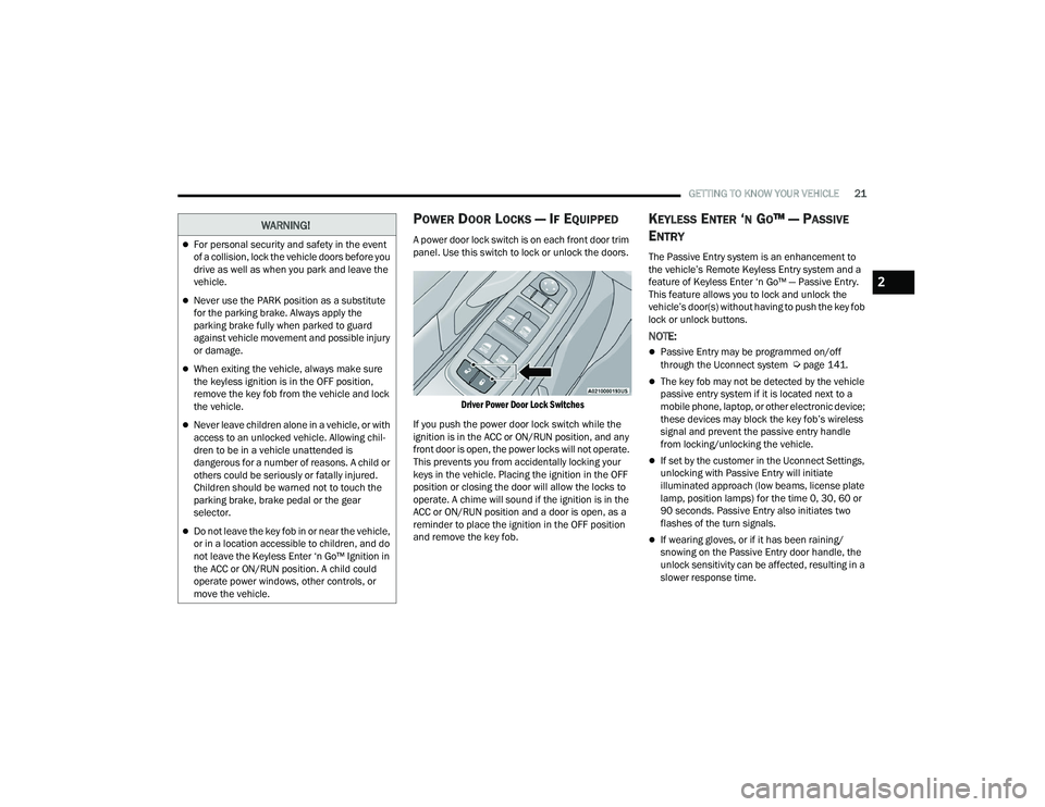
A power door lock switch is on each front door trim
panel. Use this switch to lock or unlock the doors.
Driver Power Door Lock Switches
If you push the power door lock switch while the
ignition is in the ACC or ON/RUN position, and any
front door is open, the power locks will not operate.
This prevents you from accidentally locking your
keys in the vehicle. Placing the ignition in the OFF
position or closing the door will allow the locks to
operate. A chime will sound if the ignition is in the
ACC or ON/RUN position and a door is open, as a
reminder to place the ignition in the OFF position
and remove the key fob.
KEYLESS ENTER ‘N GO™ — PASSIVE
E
NTRY
The Passive Entry system is an enhancement to
the vehicle’s Remote Keyless Entry system and a
feature of Keyless Enter ‘n Go™ — Passive Entry.
This feature allows you to lock and unlock the
vehicle’s door(s) without having to push the key fob
lock or unlock buttons.
NOTE:
Passive Entry may be programmed on/off
through the Uconnect system Úpage 141.
The key fob may not be detected by the vehicle
passive entry system if it is located next to a
mobile phone, laptop, or other electronic device;
these devices may block the key fob’s wireless
signal and prevent the passive entry handle
from locking/unlocking the vehicle.
If set by the customer in the Uconnect Settings,
unlocking with Passive Entry will initiate
illuminated approach (low beams, license plate
lamp, position lamps) for the time 0, 30, 60 or
90 seconds. Passive Entry also initiates two
flashes of the turn signals.
If wearing gloves, or if it has been raining/
snowing on the Passive Entry door handle, the
unlock sensitivity can be affected, resulting in a
slower response time.
WARNING!
For personal security and safety in the event
of a collision, lock the vehicle doors before you
drive as well as when you park and leave the
vehicle.
Never use the PARK position as a substitute
for the parking brake. Always apply the
parking brake fully when parked to guard
against vehicle movement and possible injury
or damage.
When exiting the vehicle, always make sure
the keyless ignition is in the OFF position,
remove the key fob from the vehicle and lock
the vehicle.
Never leave children alone in a vehicle, or with
access to an unlocked vehicle. Allowing chil -
dren to be in a vehicle unattended is
dangerous for a number of reasons. A child or
others could be seriously or fatally injured.
Children should be warned not to touch the
parking brake, brake pedal or the gear
selector.
Do not leave the key fob in or near the vehicle,
or in a location accessible to children, and do
not leave the Keyless Enter ‘n Go™ Ignition in
the ACC or ON/RUN position. A child could
operate power windows, other controls, or
move the vehicle.
2
22_RUVG_OM_EN_USC_t.book Page 21
Page 43 of 316
GETTING TO KNOW YOUR VEHICLE41
7. Lay the floor panel flat and push down until it clicks into position.
Push Down To Lock
8. Readjust the front seat as needed, and replace the floor mat (if equipped).
POWER ADJUSTMENT (FRONT SEATS) —
I
F EQUIPPED
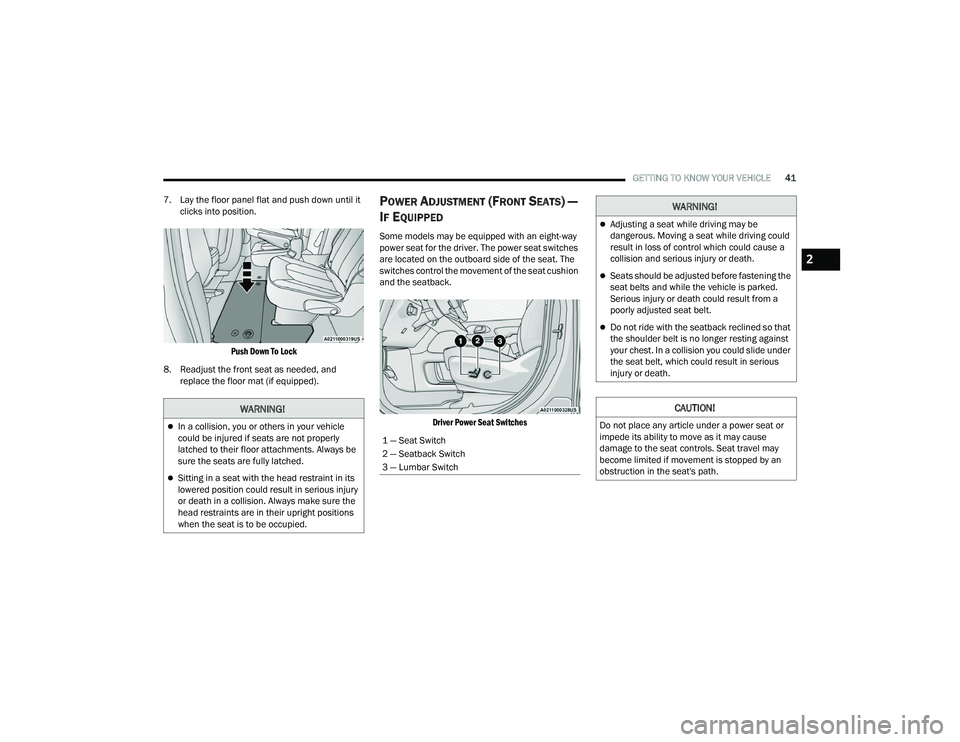
Some models may be equipped with an eight-way
power seat for the driver. The power seat switches
are located on the outboard side of the seat. The
switches control the movement of the seat cushion
and the seatback.
Driver Power Seat Switches
WARNING!
In a collision, you or others in your vehicle
could be injured if seats are not properly
latched to their floor attachments. Always be
sure the seats are fully latched.
Sitting in a seat with the head restraint in its
lowered position could result in serious injury
or death in a collision. Always make sure the
head restraints are in their upright positions
when the seat is to be occupied.
1 — Seat Switch
2 — Seatback Switch
3 — Lumbar Switch
WARNING!
Adjusting a seat while driving may be
dangerous. Moving a seat while driving could
result in loss of control which could cause a
collision and serious injury or death.
Seats should be adjusted before fastening the
seat belts and while the vehicle is parked.
Serious injury or death could result from a
poorly adjusted seat belt.
Do not ride with the seatback reclined so that
the shoulder belt is no longer resting against
your chest. In a collision you could slide under
the seat belt, which could result in serious
injury or death.
CAUTION!
Do not place any article under a power seat or
impede its ability to move as it may cause
damage to the seat controls. Seat travel may
become limited if movement is stopped by an
obstruction in the seat's path.
2
22_RUVG_OM_EN_USC_t.book Page 41
Page 51 of 316
GETTING TO KNOW YOUR VEHICLE49
Illuminated Mirror
OUTSIDE MIRRORS
The outside mirror(s) can be adjusted to the center
of the adjacent lane of traffic to achieve the
optimal view.
CONVERSATION MIRROR
Located in the overhead console there is a
conversation mirror to view all the passengers in
the vehicle. Push the panel to release the drop
down mirror. Raise the mirror and push to latch it
back in the stowed position.
Conversation Mirror
POWER MIRRORS — IF EQUIPPED
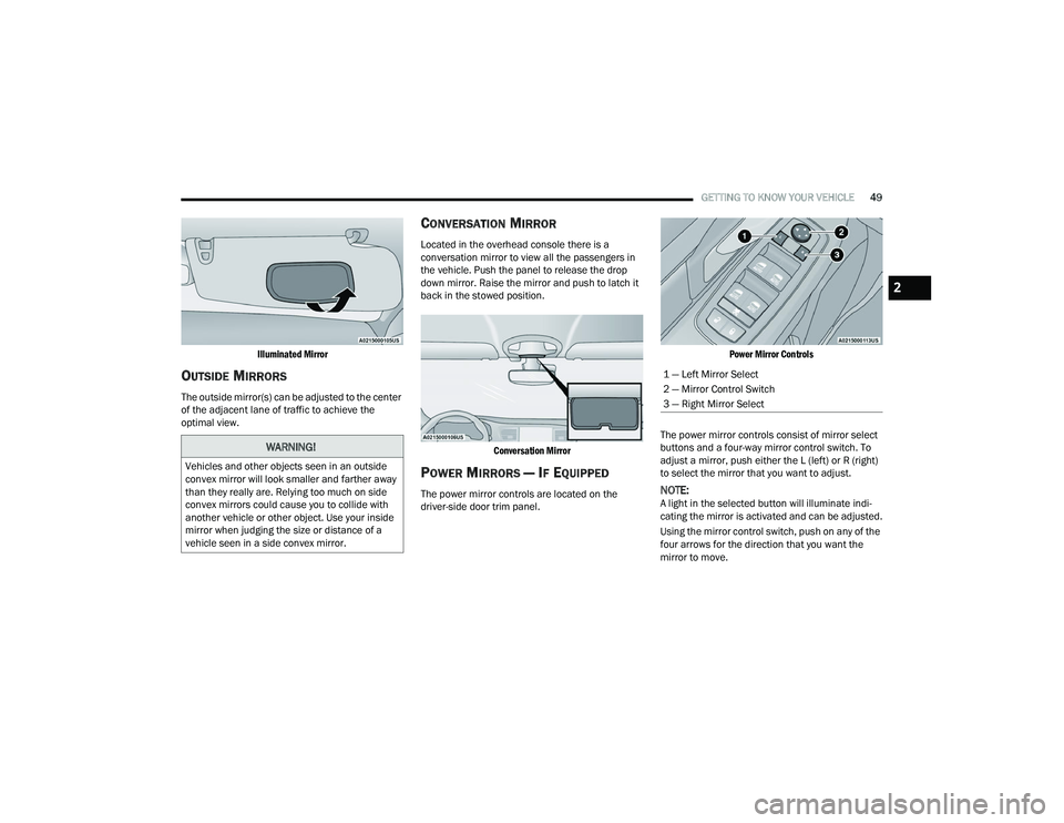
The power mirror controls are located on the
driver-side door trim panel.
Power Mirror Controls
The power mirror controls consist of mirror select
buttons and a four-way mirror control switch. To
adjust a mirror, push either the L (left) or R (right)
to select the mirror that you want to adjust.NOTE:A light in the selected button will illuminate indi -
cating the mirror is activated and can be adjusted.
Using the mirror control switch, push on any of the
four arrows for the direction that you want the
mirror to move.
WARNING!
Vehicles and other objects seen in an outside
convex mirror will look smaller and farther away
than they really are. Relying too much on side
convex mirrors could cause you to collide with
another vehicle or other object. Use your inside
mirror when judging the size or distance of a
vehicle seen in a side convex mirror.
1 — Left Mirror Select
2 — Mirror Control Switch
3 — Right Mirror Select
2
22_RUVG_OM_EN_USC_t.book Page 49
Page 56 of 316
54GETTING TO KNOW YOUR VEHICLE
If you have any problems, or require assistance,
please call toll-free 1-800-355-3515 or, on the
Internet at
HomeLink.com for information or
assistance.
EXTERIOR LIGHTS
MULTIFUNCTION LEVER
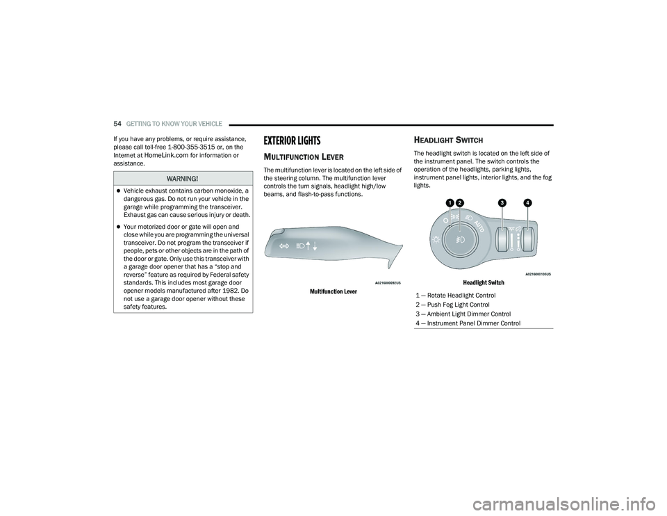
The multifunction lever is located on the left side of
the steering column. The multifunction lever
controls the turn signals, headlight high/low
beams, and flash-to-pass functions.
Multifunction Lever
HEADLIGHT SWITCH
The headlight switch is located on the left side of
the instrument panel. The switch controls the
operation of the headlights, parking lights,
instrument panel lights, interior lights, and the fog
lights.
Headlight Switch
WARNING!
Vehicle exhaust contains carbon monoxide, a
dangerous gas. Do not run your vehicle in the
garage while programming the transceiver.
Exhaust gas can cause serious injury or death.
Your motorized door or gate will open and
close while you are programming the universal
transceiver. Do not program the transceiver if
people, pets or other objects are in the path of
the door or gate. Only use this transceiver with
a garage door opener that has a “stop and
reverse” feature as required by Federal safety
standards. This includes most garage door
opener models manufactured after 1982. Do
not use a garage door opener without these
safety features.
1 — Rotate Headlight Control
2 — Push Fog Light Control
3 — Ambient Light Dimmer Control
4 — Instrument Panel Dimmer Control
22_RUVG_OM_EN_USC_t.book Page 54
Page 57 of 316
GETTING TO KNOW YOUR VEHICLE55
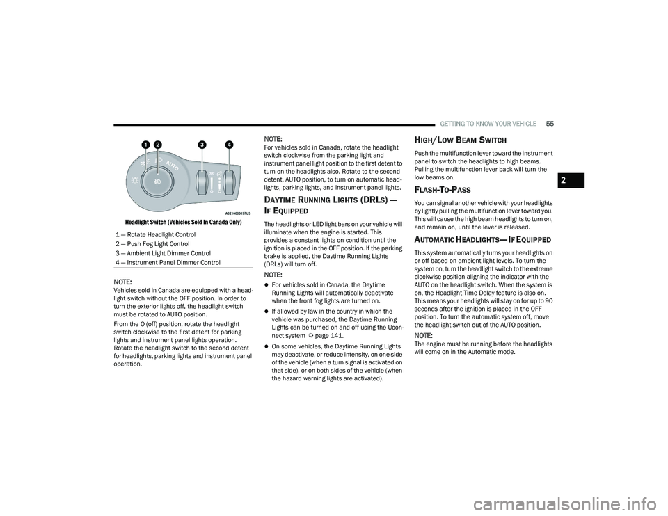
Headlight Switch (Vehicles Sold In Canada Only)
NOTE:Vehicles sold in Canada are equipped with a head -
light switch without the OFF position. In order to
turn the exterior lights off, the headlight switch
must be rotated to AUTO position.
From the O (off) position, rotate the headlight
switch clockwise to the first detent for parking
lights and instrument panel lights operation.
Rotate the headlight switch to the second detent
for headlights, parking lights and instrument panel
operation.
NOTE:For vehicles sold in Canada, rotate the headlight
switch clockwise from the parking light and
instrument panel light position to the first detent to
turn on the headlights also. Rotate to the second
detent, AUTO position, to turn on automatic head -
lights, parking lights, and instrument panel lights.
DAYTIME RUNNING LIGHTS (DRLS) —
I
F EQUIPPED
The headlights or LED light bars on your vehicle will
illuminate when the engine is started. This
provides a constant lights on condition until the
ignition is placed in the OFF position. If the parking
brake is applied, the Daytime Running Lights
(DRLs) will turn off.
NOTE:
For vehicles sold in Canada, the Daytime
Running Lights will automatically deactivate
when the front fog lights are turned on.
If allowed by law in the country in which the
vehicle was purchased, the Daytime Running
Lights can be turned on and off using the Ucon -
nect system
Úpage 141.
On some vehicles, the Daytime Running Lights
may deactivate, or reduce intensity, on one side
of the vehicle (when a turn signal is activated on
that side), or on both sides of the vehicle (when
the hazard warning lights are activated).
HIGH/LOW BEAM SWITCH
Push the multifunction lever toward the instrument
panel to switch the headlights to high beams.
Pulling the multifunction lever back will turn the
low beams on.
FLASH-TO-PASS
You can signal another vehicle with your headlights
by lightly pulling the multifunction lever toward you.
This will cause the high beam headlights to turn on,
and remain on, until the lever is released.
AUTOMATIC HEADLIGHTS — IF EQUIPPED
This system automatically turns your headlights on
or off based on ambient light levels. To turn the
system on, turn the headlight switch to the extreme
clockwise position aligning the indicator with the
AUTO on the headlight switch. When the system is
on, the Headlight Time Delay feature is also on.
This means your headlights will stay on for up to 90
seconds after the ignition is placed in the OFF
position. To turn the automatic system off, move
the headlight switch out of the AUTO position.
NOTE:The engine must be running before the headlights
will come on in the Automatic mode.
1 — Rotate Headlight Control
2 — Push Fog Light Control
3 — Ambient Light Dimmer Control
4 — Instrument Panel Dimmer Control
2
22_RUVG_OM_EN_USC_t.book Page 55
Page 60 of 316
58GETTING TO KNOW YOUR VEHICLE
Dimmer Controls
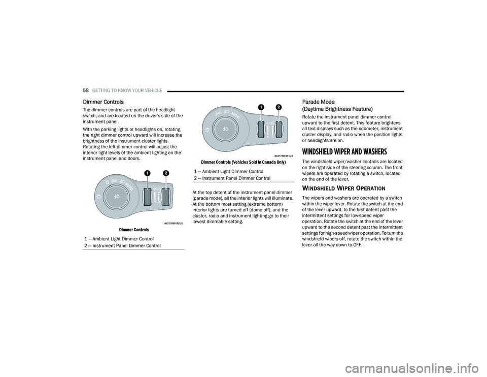
The dimmer controls are part of the headlight
switch, and are located on the driver’s side of the
instrument panel.
With the parking lights or headlights on, rotating
the right dimmer control upward will increase the
brightness of the instrument cluster lights.
Rotating the left dimmer control will adjust the
interior light levels of the ambient lighting on the
instrument panel and doors.
Dimmer Controls Dimmer Controls (Vehicles Sold In Canada Only)
At the top detent of the instrument panel dimmer
(parade mode), all the interior lights will illuminate.
At the bottom most setting (extreme bottom)
interior lights are turned off (dome off), and the
cluster, radio and instrument lighting go to their
lowest dimmable setting.
Parade Mode
(Daytime Brightness Feature)
Rotate the instrument panel dimmer control
upward to the first detent. This feature brightens
all text displays such as the odometer, instrument
cluster display, and radio when the position lights
or headlights are on.
WINDSHIELD WIPER AND WASHERS
The windshield wiper/washer controls are located
on the right side of the steering column. The front
wipers are operated by rotating a switch, located
on the end of the lever.
WINDSHIELD WIPER OPERATION
The wipers and washers are operated by a switch
within the wiper lever. Rotate the switch at the end
of the lever upward, to the first detent past the
intermittent settings for low-speed wiper
operation. Rotate the switch at the end of the lever
upward to the second detent past the intermittent
settings for high-speed wiper operation. To turn the
windshield wipers off, rotate the switch within the
lever all the way down to OFF.
1 — Ambient Light Dimmer Control
2 — Instrument Panel Dimmer Control
1 — Ambient Light Dimmer Control
2 — Instrument Panel Dimmer Control
22_RUVG_OM_EN_USC_t.book Page 58
Page 64 of 316
62GETTING TO KNOW YOUR VEHICLE
Front Temperature Control
These buttons provide the driver and passenger
with independent temperature control.
Push the red button on the faceplate or
touchscreen or press and slide the
temperature bar towards the red arrow
button on the touchscreen for warmer
temperature settings.
Push the blue button on the faceplate or
touchscreen or press and slide the
temperature bar towards the blue arrow
button on the touchscreen for cooler
temperature settings.
SYNC Button
Press the SYNC button on the
touchscreen to toggle the Sync feature
on/off. The SYNC indicator is illuminated
when this feature is enabled. SYNC is
used to synchronize the front and rear passenger
temperature settings with the driver temperature
setting. Changing the front or rear passenger
temperature setting while in SYNC will
automatically exit this feature. Pressing SYNC on
the touchscreen while in the Front Climate screen
synchronizes the driver and passenger
temperatures only. In order to SYNC rear
temperature to driver temperature, the
touchscreen must be on the Rear Climate screen.
NOTE:The SYNC setting is only available on the touch -
screen.
Blower Control
Blower Control is used to regulate the
amount of air forced through the Climate
Control system. There are seven blower
speeds available.
The speeds can be selected using either the
blower control knob on the faceplate or the
buttons on the touchscreen.
Faceplate: The blower speed increases as you
turn the blower control knob clockwise from the
lowest blower setting. The blower speed
decreases as you turn the blower control knob
counterclockwise.
Touchscreen: Use the small blower icon to
reduce the blower setting and the large blower
icon to increase the blower setting. Blower
speed can also be selected by pressing the
blower bar area between the icons.
Mode Control
The airflow distribution mode can be
adjusted so air comes from the
instrument panel outlets, floor outlets,
defrost outlets and demist outlets. Faceplate:
Push the button in the center of the
knob to change the airflow distribution mode.
Touchscreen: Select Mode by pressing one of the
Mode Buttons on the touchscreen.
Panel Mode
Air comes from the outlets in the
instrument panel. Each of these outlets
can be individually adjusted to direct the
flow of air. The air vanes of the center
outlets and outboard outlets can be moved up and
down or side to side to regulate airflow direction.
There is a shut-off wheel located below the air
vanes to shut off or adjust the amount of airflow
from these outlets.
Bi-Level Mode
Air comes from the instrument panel
outlets and floor outlets. A slight amount
of air is directed through the defrost and
side window demister outlets.
NOTE:Bi-Level mode is designed under comfort condi -
tions to provide cooler air out of the panel outlets
and warmer air from the floor outlets.
22_RUVG_OM_EN_USC_t.book Page 62
Page 66 of 316
64GETTING TO KNOW YOUR VEHICLE
BLOWER CONTROL
Blower Control is used to regulate the
amount of air forced through the Climate
Control system. There are seven blower
speeds available. Adjusting the blower
causes automatic mode to switch to manual
operation. The speeds can be selected using the
buttons on the touchscreen.
PANEL MODE
Press this button on the touchscreen to
change the air distribution mode to Panel
Mode. In Panel Mode, air comes from the
outlets in the headliner. Each of these
outlets can be individually adjusted to direct the
flow of air. Moving the air vanes of the outlets to
one side will shut off the airflow.
BI-LEVEL MODE
Press this button on the touchscreen to
change the air distribution mode to
Bi-Level Mode. In Bi-Level Mode, air
comes from the headliner outlets and
floor outlets.
NOTE:Bi-Level Mode is designed under comfort condi -
tions to provide cooler air out of the panel outlets
and warmer air from the floor outlets.
FLOOR MODE
Press this button on the touchscreen to
change the air distribution mode to Floor
Mode. In Floor Mode, air comes from the
floor outlets.
REAR PASSENGER CLIMATE CONTROL OFF
BUTTON
Press and release this button to turn the
Rear Climate Controls off.
Rear Manual Temperature Control (MTC)
The rear Manual Temperature Control (MTC)
system has floor air outlets at the rear right side of
the third row seats and overhead outlets at each
outboard rear seating position. The system
provides heated air through the floor outlets or
cool, dehumidified air through the headliner
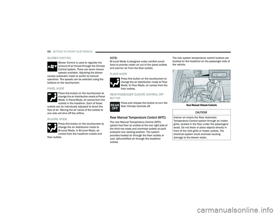
outlets. The rear system temperature control buttons are
located on the headliner on the passenger side of
the vehicle.
Rear Manual Climate Controls
CAUTION!
Interior air enters the Rear Automatic
Temperature Control system through an intake
grille, located in the floor under the passengers’
seats. Do not block or place objects directly in
front of the inlet grille or heater outlets. The
electrical system could overload causing
damage to the blower motor.
22_RUVG_OM_EN_USC_t.book Page 64
Page 67 of 316
GETTING TO KNOW YOUR VEHICLE65
REAR TEMPERATURE CONTROL
Push the up arrow button to raise the
temperature. The rear temperature
settings are displayed in control head.
Push the down arrow button to lower the
temperature. The rear temperature
settings are displayed in control head.
REAR BLOWER CONTROL
The rear blower control can be manually
set to off, or any fixed blower speed by
pushing the blower control buttons. This
allows the rear seat occupants to control
the volume of air circulated in the rear of the
vehicle. The larger of the two icons increases
blower speed, whereas the smaller of the two icons
decreases the blower speed.
REAR MODE CONTROL
Push this button on the Rear Climate
Controls to change the air distribution
mode for the rear passengers.
PANEL MODE
Air comes from the outlets in the
headliner. Each of these outlets can be
individually adjusted to direct the flow of
air. Moving the air vanes of the outlets to
one side will shut off the airflow.
BI-LEVEL MODE
Air comes from both the headliner outlets
and the floor outlets.
NOTE:In many temperature positions, the Bi-Level mode
is designed to provide cooler air out of the head -
liner outlets and warmer air from the floor outlets.
FLOOR MODE
Air comes from the floor outlets.
REAR CLIMATE CONTROL/BLOWER OFF
To manually set the rear blower controls
to off, press the Rear Climate Control/
Blower Off button.
OPERATING TIPS
Refer to the chart at the end of this section for
suggested control settings for various weather
conditions.
Summer Operation
The engine cooling system must be protected with
a high-quality antifreeze coolant to provide proper
corrosion protection and to protect against engine
overheating. OAT coolant (conforming to
MS.90032) is recommended.
Winter Operation
To ensure the best possible heater and defroster
performance, make sure the engine cooling
system is functioning properly and the proper
amount, type, and concentration of coolant is
used. Use of the Air Recirculation mode during
Winter months is not recommended, because it
may cause window fogging.
Vacation/Storage
For information on maintaining the Climate Control
system when the vehicle is being stored for an
extended period of time, see
Úpage 292.
Window Fogging
Vehicle windows tend to fog on the inside in mild,
rainy, and/or humid weather. To clear the
windows, select Defrost or Mix mode and increase
the front blower speed. Do not use the
Recirculation mode without A/C for long periods,
as fogging may occur.
2
22_RUVG_OM_EN_USC_t.book Page 65