stop start CHRYSLER VOYAGER 2023 Service Manual
[x] Cancel search | Manufacturer: CHRYSLER, Model Year: 2023, Model line: VOYAGER, Model: CHRYSLER VOYAGER 2023Pages: 256, PDF Size: 13.97 MB
Page 133 of 256
SAFETY131
Service FCW Warning
If the system turns off, and the instrument cluster
displays:
FCW Unavailable Service Required
Cruise/FCW Unavailable Service Required
This indicates there is an internal system fault. Although
the vehicle is still drivable under normal conditions, have
the system checked by an authorized dealer.
Pedestrian Emergency Braking (PEB) —
If Equipped
The Pedestrian Emergency Braking (PEB) is a subsystem
of the FCW system that provides the driver with audible
and visual warnings in the instrument cluster display, and
may apply automatic braking when it detects a potential
frontal collision with a pedestrian/cyclist.
If a PEB event begins at a speed below 37 mph (60 km/h),
the system may provide braking to mitigate the potential
collision with a pedestrian/cyclist. If the PEB event stops
the vehicle completely, the system will hold the vehicle at
a standstill for two seconds and then release the brakes.
When the system determines a collision with the
pedestrian in front of you is no longer probable, the
warning message will be deactivated.
The minimum speed for PEB activation is 3 mph (5 km/h). Turning PEB On Or Off
NOTE:
The default status of PEB is “On.” This allows the system to
warn you of a possible frontal collision with the pedestrian.
The PEB button is located in the Uconnect display in the
Controls settings
Úpage 105.
To turn the PEB system off, push the Pedestrian
Emergency Braking OFF button.
To turn the PEB system back on, push the Warning Active
Braking button.
Changing the PEB status to “Off” deactivates the system,
so no warning or active braking will be available in case of
a possible frontal collision with the pedestrian.
NOTE:The PEB system will NOT retain the last setting selected by
the driver after ignition shut down. The system will reset to
the default setting when the vehicle is restarted.
TIRE PRESSURE MONITORING
S
YSTEM (TPMS)
The Tire Pressure Monitoring System (TPMS) will warn
the driver of a low tire pressure based on the vehicle
recommended cold placard pressure.
NOTE:
The TPMS Warning Light will illuminate in the instrument
cluster and a chime will sound when tire pressure is low in one
or more of the four active road tires. In addition, the instrument
cluster will display a graphic showing the pressure values of
each tire with the low tire pressure values in a different color,
or the Uconnect radio will display a TPMS message. When this
occurs you must increase the tire pressure to the recom -
mended cold placard pressure in order for the TPMS Warning
Light to turn off.
The tire pressure will vary with temperature by
approximately 1 psi (7 kPa) for every 12°F (6.5°C). This
means that when the outside temperature decreases, the
tire pressure will decrease. Tire pressure should always be
set based on cold inflation tire pressure. This is defined as
the tire pressure after the vehicle has not been driven for
at least three hours, or driven less than 1 mile (1.6 km)
after a three hour period. The cold tire inflation pressure
must not exceed the maximum inflation pressure molded
into the tire sidewall. The tire pressure will also increase
as the vehicle is driven. This is normal and there should be
no adjustment for this increased pressure.
See
Úpage 224 for information on how to properly inflate
the vehicle’s tires.
WARNING!
Pedestrian Emergency Braking (PEB) is not intended to
avoid a collision on its own, nor can PEB detect every
type of potential collision with a pedestrian. The driver
has the responsibility to avoid a collision by controlling
the vehicle via braking and steering. Failure to follow
this warning could lead to serious injury or death.
6
23_RUV_OM_EN_US_t.book Page 131
Page 137 of 256
SAFETY135
(Continued)
SEAT BELT SYSTEMS
Buckle up even though you are an excellent driver, even
on short trips. Someone on the road may be a poor driver
and could cause a collision that includes you. This can
happen far away from home or on your own street.
Research has shown that seat belts save lives, and they can
reduce the seriousness of injuries in a collision. Some of the
worst injuries happen when people are thrown from the vehicle.
Seat belts reduce the possibility of ejection and the risk of injury
caused by striking the inside of the vehicle. Everyone in a motor
vehicle should be belted at all times.
Enhanced Seat Belt Use Reminder System
(BeltAlert)
Driver And Passenger BeltAlert — If Equipped
BeltAlert is a feature intended to remind the driver
and outboard front seat passenger (if equipped
with outboard front passenger seat BeltAlert) to
buckle their seat belts. The BeltAlert feature is
active whenever the ignition switch is in the START or ON/RUN
position.
Initial Indication
If the driver is unbuckled when the ignition switch is first in
the START or ON/RUN position, a chime will signal for a
few seconds. If the driver or outboard front seat passenger
(if equipped with outboard front passenger seat BeltAlert)
is unbuckled when the ignition switch is first in the START
or ON/RUN position the Seat Belt Reminder Light will turn
on and remain on until both outboard front seat belts are
buckled. The outboard front passenger seat BeltAlert is
not active when an outboard front passenger seat is
unoccupied. BeltAlert Warning Sequence
The BeltAlert warning sequence is activated when the vehicle is
moving above a specified vehicle speed range and the driver or
outboard front seat passenger is unbuckled (if equipped with
outboard front passenger seat BeltAlert) (the outboard front
passenger seat BeltAlert is not active when the outboard front
passenger seat is unoccupied). The BeltAlert warning sequence
starts by blinking the Seat Belt Reminder Light and sounding an
intermittent chime. Once the BeltAlert warning sequence has
completed, the Seat Belt Reminder Light will remain on until
the seat belts are buckled. The BeltAlert warning sequence may
repeat based on vehicle speed until the driver and occupied
outboard front seat passenger seat belts are buckled. The
driver should instruct all occupants to buckle their seat belts.
Change Of Status
If the driver or outboard front seat passenger (if equipped
with outboard front passenger seat BeltAlert) unbuckles
their seat belt while the vehicle is traveling, the BeltAlert
warning sequence will begin until the seat belts are
buckled again.
The outboard front passenger seat BeltAlert is not active
when the outboard front passenger seat is unoccupied.
BeltAlert may be triggered when an animal or other items
are placed on the outboard front passenger seat or when
the seat is folded flat (if equipped). It is recommended that
pets be restrained in the rear seat (if equipped) in pet
harnesses or pet carriers that are secured by seat belts,
and cargo is properly stowed.
BeltAlert can be activated or deactivated by an authorized
dealer. FCA US LLC does not recommend deactivating
BeltAlert.
NOTE:If BeltAlert has been deactivated and the driver or
outboard front seat passenger (if equipped with outboard
front passenger seat BeltAlert) is unbuckled the Seat Belt
Reminder Light will turn on and remain on until the driver
and outboard front seat passenger seat belts are buckled.
Lap/Shoulder Belts
All seating positions in your vehicle are equipped with
lap/shoulder belts.
The seat belt webbing retractor will lock only during
very sudden stops or collisions. This feature allows the
shoulder part of the seat belt to move freely with you
under normal conditions. However, in a collision the seat
belt will lock and reduce your risk of striking the inside of
the vehicle or being thrown out of the vehicle.
WARNING!
Relying on the air bags alone could lead to more
severe injuries in a collision. The air bags work with
your seat belt to restrain you properly. In some colli -
sions, the air bags won’t deploy at all. Always wear
your seat belt even though you have air bags.
In a collision, you and your passengers can suffer
much greater injuries if you are not properly buckled
up. You can strike the interior of your vehicle or other
passengers, or you can be thrown out of the vehicle.
Always be sure you and others in your vehicle are
buckled up properly.
It is dangerous to ride in a cargo area, inside or outside of
a vehicle. In a collision, people riding in these areas are
more likely to be seriously injured or killed.
6
23_RUV_OM_EN_US_t.book Page 135
Page 154 of 256
152SAFETY
(Continued)
Do not drive your vehicle after the air bags have deployed.
If you are involved in another collision, the air bags will not
be in place to protect you.
NOTE:
Air bag covers may not be obvious in the interior trim,
but they will open during air bag deployment.
After any collision, the vehicle should be taken to an
authorized dealer immediately.
Enhanced Accident Response System
In the event of an impact, if the communication network
remains intact, and the power remains intact, depending
on the nature of the event, the ORC will determine whether
to have the Enhanced Accident Response System perform
the following functions:
Cut off fuel to the engine (if equipped).
Cut off battery power to the electric motor (if equipped).
Flash hazard lights as long as the battery has power.
Turn on the interior lights, which remain on as long as
the battery has power or for 15 minutes from the inter -
vention of the Enhanced Accident Response System.
Unlock the power door locks. Your vehicle may also be designed to perform any of these
other functions in response to the Enhanced Accident
Response System:
Turn off the Fuel Filter Heater, Turn off the HVAC Blower
Motor, Close the HVAC Circulation Door
Cut off battery power to the:
Engine
Electric Motor (if equipped)
Electric power steering
Brake booster
Electric park brake
Automatic transmission gear selector
Horn
Front wiper
NOTE:After an accident, remember to cycle the ignition to the
STOP (OFF/LOCK) position and remove the key from the
ignition switch to avoid draining the battery. Carefully
check the vehicle for fuel leaks in the engine compartment
and on the ground near the engine compartment and fuel
tank before resetting the system and starting the engine.
If there are no fuel leaks or damage to the vehicle elec -
trical devices (e.g. headlights) after an accident, reset the
system by following the procedure described below. If you
have any doubt, contact an authorized dealer.
Enhanced Accident Response System
Reset Procedure
In order to reset the Enhanced Accident Response System
functions after an event, the ignition switch must be changed
from ignition START or ON/RUN to ignition OFF. Carefully check
the vehicle for fuel leaks in the engine compartment and on the
ground near the engine compartment and fuel tank before
resetting the system and starting the engine.
After an accident, if the vehicle will not start after
performing the reset procedure, the vehicle must be
towed to an authorized dealer to be inspected and to
have the Enhanced Accident Response System reset.
Maintaining Your Air Bag System
WARNING!
Deployed air bags and seat belt pretensioners cannot
protect you in another collision. Have the air bags, seat
belt pretensioners, and the seat belt retractor assemblies
replaced by an authorized dealer immediately. Also, have the
Occupant Restraint Controller System serviced as well.
WARNING!
Modifications to any part of the air bag system could
cause it to fail when you need it. You could be injured
if the air bag system is not there to protect you.
Do not modify the components or wiring, including
adding any kind of badges or stickers to the steering
wheel hub trim cover or the upper passenger side of
the instrument panel. Do not modify the front fascia/
bumper, vehicle body structure, or add aftermarket
side steps or running boards.
It is dangerous to try to repair any part of the air bag
system yourself. Be sure to tell anyone who works on
your vehicle that it has an air bag system.
23_RUV_OM_EN_US_t.book Page 152
Page 179 of 256
IN CASE OF EMERGENCY177
3. Place the wrench on the jack screw and turn
clockwise until the jack head is properly engaged in
the described location. Do not raise the vehicle until
you are sure the jack is securely engaged.
4. Raise the vehicle by turning the jack screw clockwise, using the swivel wrench. Raise the vehicle only until
the tire just clears the surface and enough clearance
is obtained to install the compact spare tire.
Minimum tire lift provides maximum stability.
5. Remove the wheel lug nuts, for vehicles with wheel covers, remove the cover from the wheel by hand.
Do not pry the wheel cover off. Then pull the wheel off
the hub.
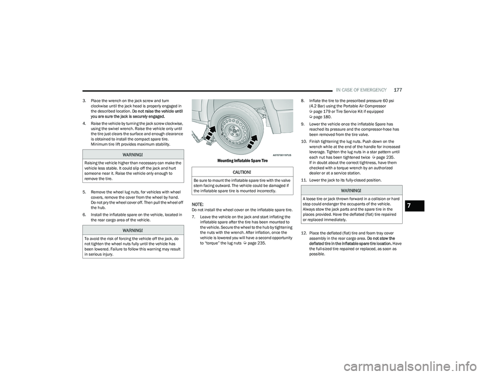
6. Install the inflatable spare on the vehicle, located in the rear cargo area of the vehicle.
Mounting Inflatable Spare Tire
NOTE:
Do not install the wheel cover on the inflatable spare tire.
7. Leave the vehicle on the jack and start inflating the inflatable spare after the tire has been mounted to
the vehicle. Secure the wheel to the hub by tightening
the nuts with the wrench. After inflation, once the
vehicle is lowered you will have a second opportunity
to “torque” the lug nuts
Úpage 235. 8. Inflate the tire to the prescribed pressure 60 psi
(4.2 Bar) using the Portable Air Compressor
Úpage 179 or Tire Service Kit if equipped Úpage 180.
9. Lower the vehicle once the inflatable Spare has reached its pressure and the compressor-hose has
been removed from the tire valve.
10. Finish tightening the lug nuts. Push down on the wrench while at the end of the handle for increased
leverage. Tighten the lug nuts in a star pattern until
each nut has been tightened twice
Úpage 235.
If in doubt about the correct tightness, have them
checked with a torque wrench by an authorized
dealer or at a service station.
11. Lower the jack to its fully-closed position.
12. Place the deflated (flat) tire and foam tray cover assembly in the rear cargo area. Do not stow the
deflated tire in the inflatable spare tire location. Have
the full-sized tire repaired or replaced, as soon as
possible.WARNING!
Raising the vehicle higher than necessary can make the
vehicle less stable. It could slip off the jack and hurt
someone near it. Raise the vehicle only enough to
remove the tire.
WARNING!
To avoid the risk of forcing the vehicle off the jack, do
not tighten the wheel nuts fully until the vehicle has
been lowered. Failure to follow this warning may result
in serious injury.
CAUTION!
Be sure to mount the inflatable spare tire with the valve
stem facing outward. The vehicle could be damaged if
the inflatable spare tire is mounted incorrectly.
WARNING!
A loose tire or jack thrown forward in a collision or hard
stop could endanger the occupants of the vehicle.
Always stow the jack parts and the spare tire in the
places provided. Have the deflated (flat) tire repaired
or replaced immediately.
7
23_RUV_OM_EN_US_t.book Page 177
Page 184 of 256
182IN CASE OF EMERGENCY
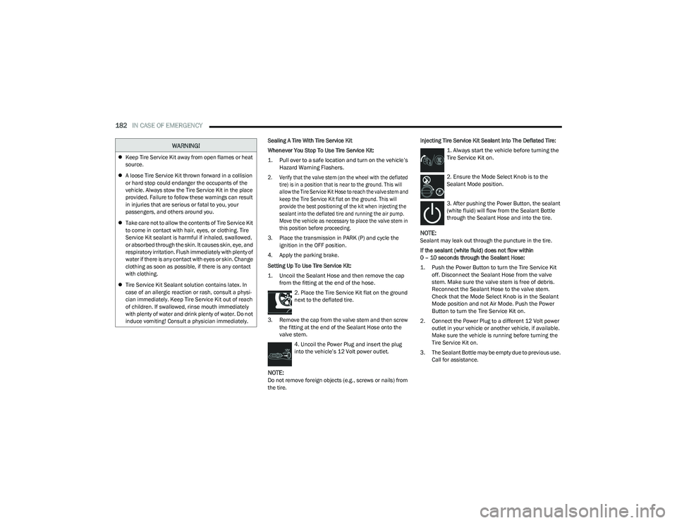
Sealing A Tire With Tire Service Kit
Whenever You Stop To Use Tire Service Kit:
1. Pull over to a safe location and turn on the vehicle’s
Hazard Warning Flashers.
2. Verify that the valve stem (on the wheel with the deflated tire) is in a position that is near to the ground. This will
allow the Tire Service Kit Hose to reach the valve stem and
keep the Tire Service Kit flat on the ground. This will
provide the best positioning of the kit when injecting the
sealant into the deflated tire and running the air pump.
Move the vehicle as necessary to place the valve stem in
this position before proceeding.
3. Place the transmission in PARK (P) and cycle the ignition in the OFF position.
4. Apply the parking brake.
Setting Up To Use Tire Service Kit:
1. Uncoil the Sealant Hose and then remove the cap from the fitting at the end of the hose.
2. Place the Tire Service Kit flat on the ground
next to the deflated tire.
3. Remove the cap from the valve stem and then screw the fitting at the end of the Sealant Hose onto the
valve stem.
4. Uncoil the Power Plug and insert the plug
into the vehicle’s 12 Volt power outlet.
NOTE:Do not remove foreign objects (e.g., screws or nails) from
the tire. Injecting Tire Service Kit Sealant Into The Deflated Tire:
1. Always start the vehicle before turning the
Tire Service Kit on.
2. Ensure the Mode Select Knob is to the
Sealant Mode position.
3. After pushing the Power Button, the sealant
(white fluid) will flow from the Sealant Bottle
through the Sealant Hose and into the tire.
NOTE:Sealant may leak out through the puncture in the tire.
If the sealant (white fluid) does not flow within
0 – 10 seconds through the Sealant Hose:
1. Push the Power Button to turn the Tire Service Kit off. Disconnect the Sealant Hose from the valve
stem. Make sure the valve stem is free of debris.
Reconnect the Sealant Hose to the valve stem.
Check that the Mode Select Knob is in the Sealant
Mode position and not Air Mode. Push the Power
Button to turn the Tire Service Kit on.
2. Connect the Power Plug to a different 12 Volt power outlet in your vehicle or another vehicle, if available.
Make sure the vehicle is running before turning the
Tire Service Kit on.
3. The Sealant Bottle may be empty due to previous use. Call for assistance.
Keep Tire Service Kit away from open flames or heat
source.
A loose Tire Service Kit thrown forward in a collision
or hard stop could endanger the occupants of the
vehicle. Always stow the Tire Service Kit in the place
provided. Failure to follow these warnings can result
in injuries that are serious or fatal to you, your
passengers, and others around you.
Take care not to allow the contents of Tire Service Kit
to come in contact with hair, eyes, or clothing. Tire
Service Kit sealant is harmful if inhaled, swallowed,
or absorbed through the skin. It causes skin, eye, and
respiratory irritation. Flush immediately with plenty of
water if there is any contact with eyes or skin. Change
clothing as soon as possible, if there is any contact
with clothing.
Tire Service Kit Sealant solution contains latex. In
case of an allergic reaction or rash, consult a physi -
cian immediately. Keep Tire Service Kit out of reach
of children. If swallowed, rinse mouth immediately
with plenty of water and drink plenty of water. Do not
induce vomiting! Consult a physician immediately.
WARNING!
23_RUV_OM_EN_US_t.book Page 182
Page 198 of 256
196SERVICING AND MAINTENANCE
CHECKING OIL LEVEL
To ensure proper engine lubrication, the engine oil must
be maintained at the correct level. Check the oil level at
regular intervals, such as every fuel stop. The best time to
check the engine oil level is about five minutes after a fully
warmed up engine is shut off.
Checking the oil while the vehicle is on level ground will
improve the accuracy of the oil level readings.
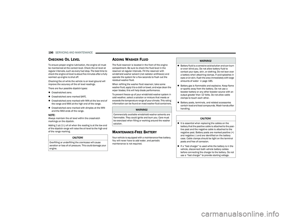
There are four possible dipstick types:
Crosshatched zone.
Crosshatched zone marked SAFE.
Crosshatched zone marked with MIN at the low end of
the range and MAX at the high end of the range.
Crosshatched zone marked with dimples at the MIN
and the MAX ends of the range.
NOTE:Always maintain the oil level within the crosshatch
markings on the dipstick.
Adding 1 qt (1 L) of oil when the reading is at the low end
of the dipstick range will raise the oil level to the high end
of the range marking.
ADDING WASHER FLUID
The fluid reservoir is located in the front of the engine
compartment. Be sure to check the fluid level in the
reservoir at regular intervals. Fill the reservoir with
windshield washer solvent (not radiator antifreeze) and
operate the system for a few seconds to flush out the
residual washer fluid.
When refilling the washer fluid reservoir, take some
washer fluid, apply it to a cloth or towel, and wipe clean the
wiper blades; this will help blade performance.
To prevent freeze-up of your windshield washer system in
cold weather, select a solution or mixture that meets or
exceeds the temperature range of your climate. This rating
information can be found on most washer fluid containers.
MAINTENANCE-FREE BATTERY
Your vehicle is equipped with a maintenance-free battery.
You will never have to add water, and periodic
maintenance is not required.CAUTION!
Overfilling or underfilling the crankcase will cause
aeration or loss of oil pressure. This could damage your
engine.
WARNING!
Commercially available windshield washer solvents are
flammable. They could ignite and burn you. Care must
be exercised when filling or working around the washer
solution.
WARNING!
Battery fluid is a corrosive acid solution and can burn
or even blind you. Do not allow battery fluid to
contact your eyes, skin, or clothing. Do not lean over
a battery when attaching clamps. If acid splashes in
eyes or on skin, flush the area immediately with large
amounts of water
Úpage 185.
Battery gas is flammable and explosive. Keep flame
or sparks away from the battery. Do not use a
booster battery or any other booster source with an
output greater than 12 Volts. Do not allow cable
clamps to touch each other.
Battery posts, terminals, and related accessories
contain lead and lead compounds. Wash hands after
handling.
CAUTION!
It is essential when replacing the cables on the
battery that the positive cable is attached to the posi -
tive post and the negative cable is attached to the
negative post. Battery posts are marked positive (+)
and negative (-) and are identified on the battery
case. Cable clamps should be tight on the terminal
posts and free of corrosion.
If a “fast charger” is used while the battery is in the
vehicle, disconnect both vehicle battery cables
before connecting the charger to the battery. Do not
use a “fast charger” to provide starting voltage.
23_RUV_OM_EN_US_t.book Page 196
Page 201 of 256
SERVICING AND MAINTENANCE199
AIR CONDITIONER MAINTENANCE
For best possible performance, your air conditioner should
be checked and serviced by an authorized dealer at the
start of each warm season. This service should include
cleaning of the condenser fins and a performance test.
Drive belt tension should also be checked at this time.
Refrigerant Recovery And Recycling —
R–1234yf
R–1234yf Air Conditioning Refrigerant is a Hydrofluo -
roolefin (HFO) that is endorsed by the Environmental
Protection Agency and is an ozone-friendly substance with
a low global-warming potential. It is recommended that air
conditioning service be performed by an authorized dealer
using recovery and recycling equipment.
NOTE:Use only manufacturer approved A/C system PAG
compressor oil, and refrigerants.
Cabin Air Filter
The cabin air filter is located in the fresh air inlet behind
the glove compartment. Perform the following procedure
to replace the filter:
1. Remove all contents from the glove compartment.
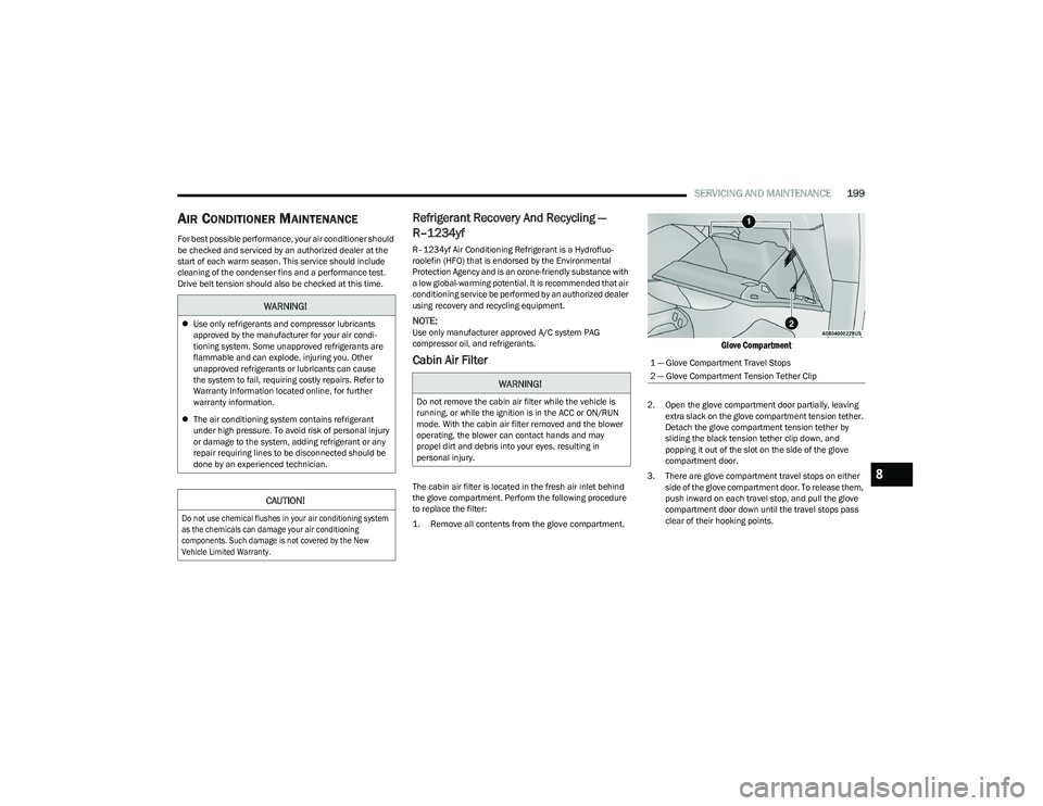
Glove Compartment
2. Open the glove compartment door partially, leaving extra slack on the glove compartment tension tether.
Detach the glove compartment tension tether by
sliding the black tension tether clip down, and
popping it out of the slot on the side of the glove
compartment door.
3. There are glove compartment travel stops on either side of the glove compartment door. To release them,
push inward on each travel stop, and pull the glove
compartment door down until the travel stops pass
clear of their hooking points.
WARNING!
Use only refrigerants and compressor lubricants
approved by the manufacturer for your air condi -
tioning system. Some unapproved refrigerants are
flammable and can explode, injuring you. Other
unapproved refrigerants or lubricants can cause
the system to fail, requiring costly repairs. Refer to
Warranty Information located online, for further
warranty information.
The air conditioning system contains refrigerant
under high pressure. To avoid risk of personal injury
or damage to the system, adding refrigerant or any
repair requiring lines to be disconnected should be
done by an experienced technician.
CAUTION!
Do not use chemical flushes in your air conditioning system
as the chemicals can damage your air conditioning
components. Such damage is not covered by the New
Vehicle Limited Warranty.
WARNING!
Do not remove the cabin air filter while the vehicle is
running, or while the ignition is in the ACC or ON/RUN
mode. With the cabin air filter removed and the blower
operating, the blower can contact hands and may
propel dirt and debris into your eyes, resulting in
personal injury.
1 — Glove Compartment Travel Stops
2 — Glove Compartment Tension Tether Clip
8
23_RUV_OM_EN_US_t.book Page 199
Page 205 of 256
SERVICING AND MAINTENANCE203
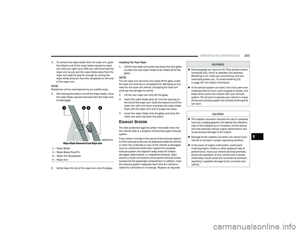
3. To remove the wiper blade from the wiper arm, grab
the bottom end of the wiper blade nearest to wiper
arm with your right hand. With your left hand hold the
wiper arm as you pull the wiper blade away from the
wiper arm past its stop far enough to unsnap the
wiper blade pivot pin from the receptacle on the end
of the wiper arm.
NOTE:Resistance will be accompanied by an audible snap.
4. Still holding the bottom end of the wiper blade, move the wiper blade upward and away from the wiper arm
to disengage.
Wiper Blade Removed From Wiper Arm
5. Gently lower the tip of the wiper arm onto the glass. Installing The Rear Wiper
1. Lift the rear wiper arm pivot cap away from the glass
to allow the rear wiper blade to be raised off of the
glass.
NOTE:
The rear wiper arm cannot be fully raised off the glass unless
the wiper arm pivot cap is unsnapped first. Attempting to fully
raise the rear wiper arm without unsnapping the wiper arm
pivot cap may damage the vehicle.
2. Lift the rear wiper arm fully off the glass.
3. Insert the wiper blade pivot pin into the opening on the end of the wiper arm. Grab the bottom end of the
wiper arm with one hand, and press the wiper blade
flush with the wiper arm until it snaps into place.
4. Lower the wiper blade onto the glass and snap the wiper arm pivot cap back into place.
EXHAUST SYSTEM
The best protection against carbon monoxide entry into
the vehicle body is a properly maintained engine exhaust
system.
If you notice a change in the sound of the exhaust system;
or if the exhaust fumes can be detected inside the vehicle;
or when the underside or rear of the vehicle is damaged;
have an authorized technician inspect the complete
exhaust system and adjacent body areas for broken,
damaged, deteriorated, or mispositioned parts. Open
seams or loose connections could permit exhaust fumes
to seep into the passenger compartment. In addition, have
the exhaust system inspected each time the vehicle is
raised for lubrication or oil change. Replace as required.
1 — Wiper Blade
2 — Wiper Blade Pivot Pin
3 — Wiper Arm Receptacle
4 — Wiper Arm
WARNING!
Exhaust gases can injure or kill. They contain carbon
monoxide (CO), which is colorless and odorless.
Breathing it can make you unconscious and can
eventually poison you. To avoid breathing CO,
Úpage 167 for further information.
A hot exhaust system can start a fire if you park over
materials that can burn, such as grass or leaves, and
those items come into contact with your exhaust
system. Do not park or operate your vehicle in areas
where your exhaust system can contact anything that
can burn.
CAUTION!
The catalytic converter requires the use of unleaded
fuel only. Leaded gasoline will destroy the effective -
ness of the catalyst as an emissions control device
and may seriously reduce engine performance and
cause serious damage to the engine.
Damage to the catalytic converter can result if your
vehicle is not kept in proper operating condition.
In the event of engine malfunction, particularly
involving engine misfire or other apparent loss of
performance, have your vehicle serviced promptly.
Continued operation of your vehicle with a severe
malfunction could cause the converter to overheat,
resulting in possible damage to the converter and
vehicle.
8
23_RUV_OM_EN_US_t.book Page 203
Page 206 of 256
204SERVICING AND MAINTENANCE
Under normal operating conditions, the catalytic converter
will not require maintenance. However, it is important to
keep the engine properly tuned to ensure proper catalyst
operation and prevent possible catalyst damage.
NOTE:Intentional tampering with emissions control systems can
result in civil penalties being assessed against you.
In unusual situations involving grossly malfunctioning
engine operation, a scorching odor may suggest severe
and abnormal catalyst overheating. If this occurs, stop the
vehicle, turn off the engine and allow it to cool. Service,
including a tune-up to the manufacturer specifications,
should be obtained immediately.
To minimize the possibility of catalytic converter damage:
Do not interrupt the ignition when the transmission is
in gear and the vehicle is in motion.
Do not try to start the vehicle by pushing or towing the
vehicle.
Do not idle the engine with any ignition components
disconnected or removed, such as when diagnostic
testing, or for prolonged periods during very rough idle
or malfunctioning operating conditions.
COOLING SYSTEM
Engine Coolant Checks
Check the engine coolant (antifreeze) protection every
12 months (before the onset of freezing weather, where
applicable). If the engine coolant is dirty, the system
should be drained, flushed, and refilled with fresh Organic
Additive Technology (OAT) coolant (conforming to
MS.90032) by an authorized dealer. Check the front of the
A/C condenser for any accumulation of bugs, leaves, etc.
If dirty, clean by gently spraying water from a garden hose
vertically down the face of the condenser. Check the engine cooling system hoses for brittle rubber,
cracking, tears, cuts, and tightness of the connection at
the coolant recovery bottle and radiator. Inspect the entire
system for leaks. DO NOT REMOVE THE COOLANT
PRESSURE CAP WHEN THE COOLING SYSTEM IS HOT.
Cooling System — Drain, Flush And Refill
NOTE:
Some vehicles require special tools to add coolant properly.
Failure to fill these systems properly could lead to severe
internal engine damage. If any coolant is needed to be added
to the system please contact an authorized dealer.
If the engine coolant (antifreeze) is dirty or contains visible
sediment, have an authorized dealer clean and flush with
Organic Additive Technology (OAT) coolant (conforming to
MS.90032).
For the proper maintenance intervals
Úpage 193.
Selection Of Coolant
For further information Úpage 238.
NOTE:
Mixing of engine coolant (antifreeze) other than speci-
fied Organic Additive Technology (OAT) engine coolant,
may result in engine damage and may decrease corro -
sion protection. OAT engine coolant is different and
should not be mixed with Hybrid Organic Additive Tech -
nology (HOAT) engine coolant or any “globally compat -
ible” coolant. If a non-OAT engine coolant is introduced
into the cooling system in an emergency, the cooling
system will need to be drained, flushed, and refilled
with fresh OAT coolant (conforming to MS.90032), by
an authorized dealer as soon as possible.
WARNING!
You or others can be badly burned by hot engine
coolant (antifreeze) or steam from your radiator.
If you see or hear steam coming from under the
hood, do not open the hood until the radiator has had
time to cool. Never open a cooling system pressure
cap when the radiator or coolant bottle is hot.
Keep hands, tools, clothing, and jewelry away from
the radiator cooling fan when the hood is raised.
The fan starts automatically and may start at any
time, whether the engine is running or not.
When working near the radiator cooling fan, discon -
nect the fan motor lead or turn the ignition to the OFF
mode. The fan is temperature controlled and can
start at any time the ignition is in the ON mode.
23_RUV_OM_EN_US_t.book Page 204