CITROEN 2CV 1975 Manual PDF
Manufacturer: CITROEN, Model Year: 1975, Model line: 2CV, Model: CITROEN 2CV 1975Pages: 86, PDF Size: 2.21 MB
Page 71 of 86
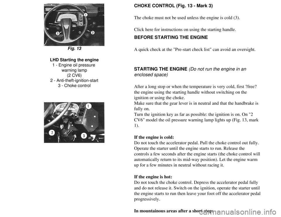
CHOKE CONTROL (Fig. 13 - Mark 3)
The choke must not be used unless the engine is cold (3).
Click here for instructions on using the starting handle.
BEFORE STARTING THE ENGINE
A quick check at the "Pre-start check list" can avoid an oversight.
Fig. 13
LHD Starting the engine 1 - Engine oil pressure warning lamp(2 CV6)
2 - Anti-theft-ignition-start 3 - Choke control
STARTING THE ENGINE (Do not run the engine in an
enclosed space)
After a long stop or when the temperature is very cold, first ?free?
the engine using the starting handle without switching on the
ignition or using the choke.
Make sure that the gear lever is in neutral and that the handbrake is
fully on.
Turn the ignition key as far as possible: the ignition is on. On "2
CV6" model the oil pressure warning lamp lights up (Fig. 13, mark
1).
If the engine is cold:
Do not touch the accelerator pedal. Pull the choke control out fully.
Operate the starter until the engine starts to run. Release the
controls a few seconds after the engine starts (the choke control will \
automatically return to its mid-way position). Let the engine warm
up for a few minutes in neutral without racing it.
If the engine is hot:
Do not touch the choke control. Depress the accelerator pedal fully
and do not release it. Switch on the ignition, operate the starter until\
the engine starts to run then leave your foot off the accelerator pedal \
progressively.
In mountainous areas after a short stop:
Page 72 of 86
Operate the starter without depressing the accelerator. If the engine
starts to run and dies, accelerate progressively to avoid stalling. If
the engine does not start at idling speed, pull the choke out to its
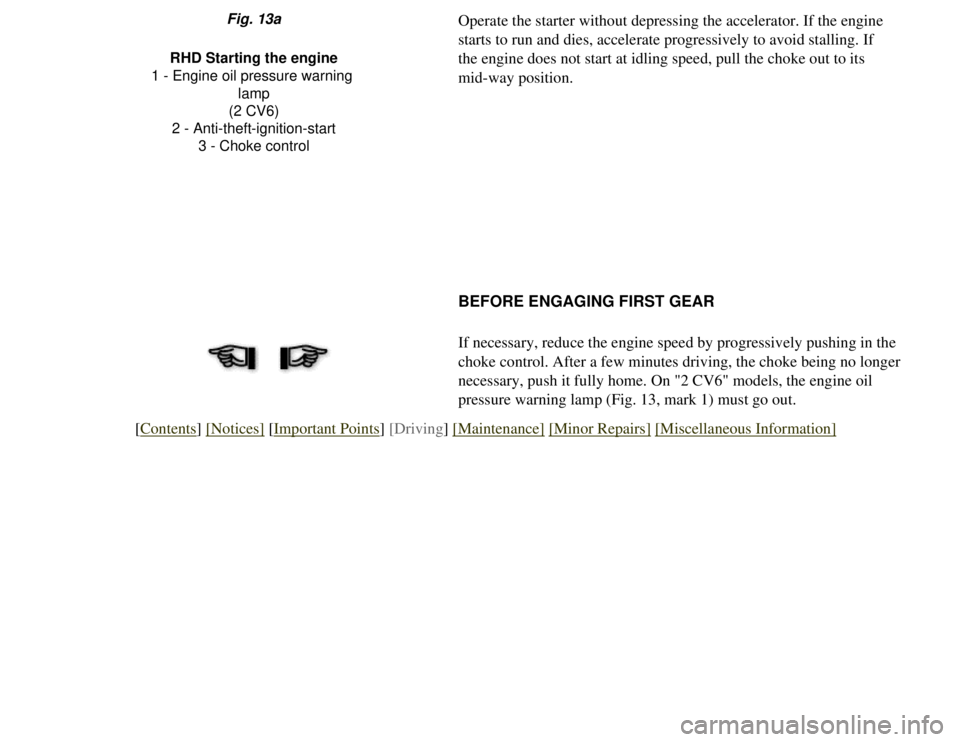
mid-way position.Fig. 13a
RHD Starting the engine
1 - Engine oil pressure warning lamp
(2 CV6)
2 - Anti-theft-ignition-start 3 - Choke control
BEFORE ENGAGING FIRST GEAR
If necessary, reduce the engine speed by progressively pushing in the
choke control. After a few minutes driving, the choke being no longer
necessary, push it fully home. On "2 CV6" models, the engine oil
pressure warning lamp (Fig. 13, mark 1) must go out.
[Contents] [Notices] [Important Points] [Driving] [Maintenance] [Minor Repairs] [Miscellaneous Information]
Page 73 of 86
DRIVING
Driving
Gears, clutch, brakes
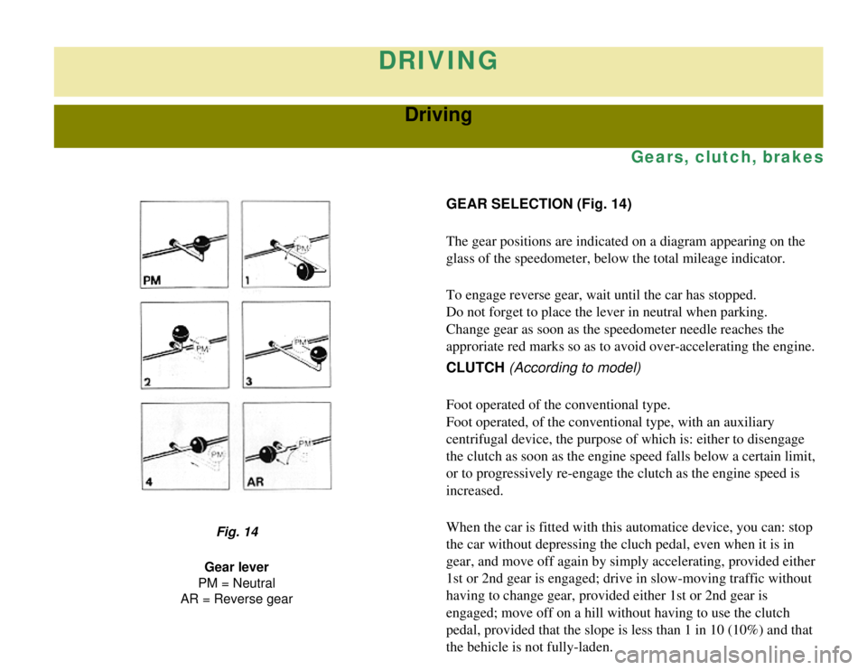
GEAR SELECTION (Fig. 14)
The gear positions are indicated on a diagram appearing on the
glass of the speedometer, below the total mileage indicator.
To engage reverse gear, wait until the car has stopped.
Do not forget to place the lever in neutral when parking.
Change gear as soon as the speedometer needle reaches the
approriate red marks so as to avoid over-accelerating the engine.
CLUTCH (According to model)
Foot operated of the conventional type.
Foot operated, of the conventional type, with an auxiliary
centrifugal device, the purpose of which is: either to disengage
the clutch as soon as the engine speed falls below a certain limit,
or to progressively re-engage the clutch as the engine speed is
increased.
When the car is fitted with this automatice device, you can: stop
the car without depressing the cluch pedal, even when it is in
gear, and move off again by simply accelerating, provided either
1st or 2nd gear is engaged; drive in slow-moving traffic without
having to change gear, provided either 1st or 2nd gear is
engaged; move off on a hill without having to use the clutch
pedal, provided that the slope is less than 1 in 10 (10%) and that
the behicle is not fully-laden.
Fig. 14
Gear lever
PM = Neutral
AR = Reverse gear
Page 74 of 86
At a speed of over about 1,000 rpm, the clutch behaves in the
same way as a conventional clutch. The clutch pedal must be
used to change gear.
When running downhill, slowing down abruptly may cause
the clutch to disengage. Re-engage the clutch immediately
with a light touch on the accelerator before the car gathers
speed in free-wheeling.
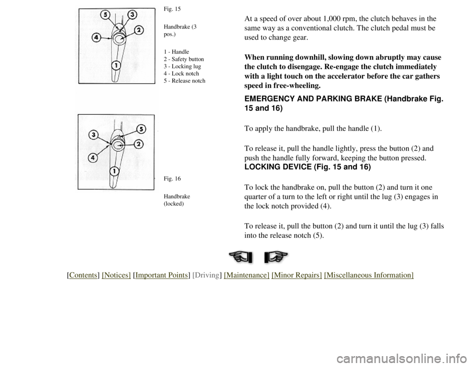
Fig. 15
Handbrake (3
pos.)
1 - Handle
2 - Safety button
3 - Locking lug
4 - Lock notch
5 - Release notch
Fig. 16
Handbrake
(locked)
EMERGENCY AND PARKING BRAKE (Handbrake Fig.
15 and 16)
To apply the handbrake, pull the handle (1).
To release it, pull the handle lightly, press the button (2) and
push the handle fully forward, keeping the button pressed.
LOCKING DEVICE (Fig. 15 and 16)
To lock the handbrake on, pull the button (2) and turn it one
quarter of a turn to the left or right until the lug (3) engages in
the lock notch provided (4).
To release it, pull the button (2) and turn it until the lug (3) fal\
ls
into the release notch (5).
[Contents] [Notices] [Important Points] [Driving] [Maintenance] [Minor Repairs] [Miscellaneous Information]
Page 75 of 86
DRIVING
Signals and Visibility
Lights, signals, windscreen wipers, windscreen washers
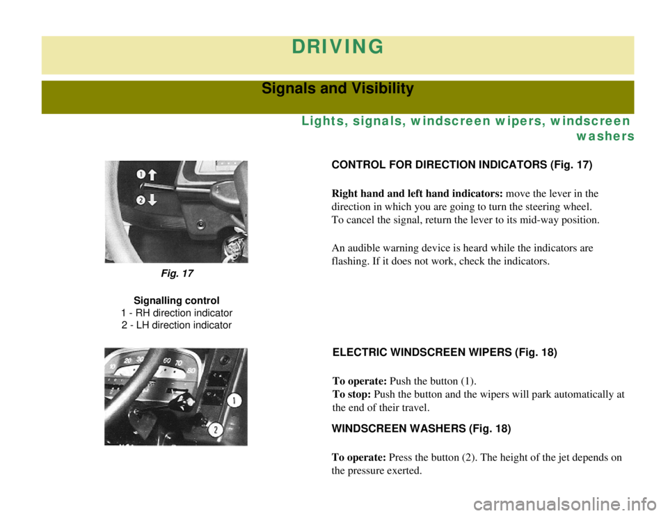
CONTROL FOR DIRECTION INDICATORS (Fig. 17)
Right hand and left hand indicators: move the lever in the
direction in which you are going to turn the steering wheel.
To cancel the signal, return the lever to its mid-way position.
An audible warning device is heard while the indicators are
flashing. If it does not work, check the indicators.
Fig. 17
Signalling control
1 - RH direction indicator 2 - LH direction indicator
ELECTRIC WINDSCREEN WIPERS (Fig. 18)
To operate: Push the button (1).
To stop: Push the button and the wipers will park automatically at
the end of their travel.
WINDSCREEN WASHERS (Fig. 18)
To operate: Press the button (2). The height of the jet depends on
the pressure exerted.
Page 76 of 86
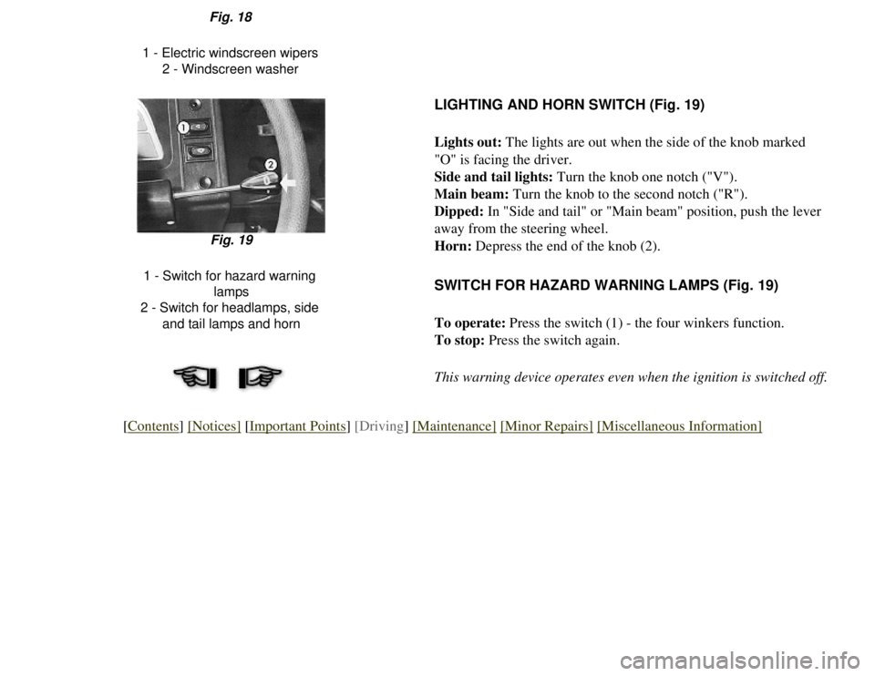
Fig. 18
1 - Electric windscreen wipers 2 - Windscreen washer
LIGHTING AND HORN SWITCH (Fig. 19)
Lights out: The lights are out when the side of the knob marked
"O" is facing the driver.
Side and tail lights: Turn the knob one notch ("V").
Main beam: Turn the knob to the second notch ("R").
Dipped: In "Side and tail" or "Main beam" position, push the lever
away from the steering wheel.
Horn: Depress the end of the knob (2).
Fig. 19
1 - Switch for hazard warning lamps
2 - Switch for headlamps, side and tail lamps and horn
SWITCH FOR HAZARD WARNING LAMPS (Fig. 19)
To operate: Press the switch (1) - the four winkers function.
To stop: Press the switch again.
This warning device operates even when the ignition is switched off.
[Contents] [Notices] [Important Points] [Driving] [Maintenance] [Minor Repairs] [Miscellaneous Information]
Page 77 of 86
DRIVING
Air Conditioning
Ventilation, heating, de-misting
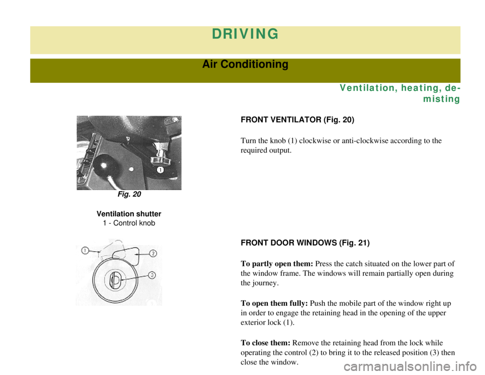
FRONT VENTILATOR (Fig. 20)
Turn the knob (1) clockwise or anti-clockwise according to the
required output.
Fig. 20
Ventilation shutter 1 - Control knob
FRONT DOOR WINDOWS (Fig. 21)
To partly open them: Press the catch situated on the lower part of
the window frame. The windows will remain partially open during
the journey.
To open them fully: Push the mobile part of the window right up
in order to engage the retaining head in the opening of the upper
exterior lock (1).
To close them: Remove the retaining head from the lock while
operating the control (2) to bring it to the released position (3) t\
hen
close the window.
Page 78 of 86
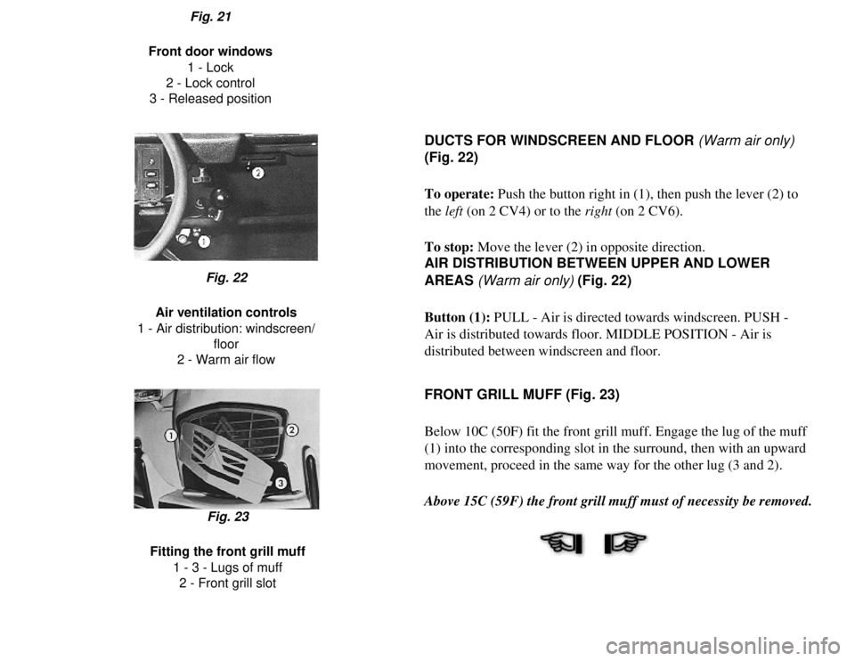
Fig. 21
Front door windows 1 - Lock
2 - Lock control
3 - Released position
DUCTS FOR WINDSCREEN AND FLOOR (Warm air only)
(Fig. 22)
To operate: Push the button right in (1), then push the lever (2) to
the left (on 2 CV4) or to the right (on 2 CV6).
To stop: Move the lever (2) in opposite direction.
AIR DISTRIBUTION BETWEEN UPPER AND LOWER
AREAS (Warm air only) (Fig. 22)
Button (1): PULL - Air is directed towards windscreen. PUSH -
Air is distributed towards floor. MIDDLE POSITION - Air is
distributed between windscreen and floor.
Fig. 22
Air ventilation controls
1 - Air distribution: windscreen/ floor
2 - Warm air flow
FRONT GRILL MUFF (Fig. 23)
Below 10C (50F) fit the front grill muff. Engage the lug of the muff
(1) into the corresponding slot in the surround, then with an upward
movement, proceed in the same way for the other lug (3 and 2).
Above 15C (59F) the front grill muff must of necessity be removed.
Fig. 23
Fitting the front grill muff 1 - 3 - Lugs of muff2 - Front grill slot
Page 79 of 86
![CITROEN 2CV 1975 Manual PDF
[Contents] [Notices] [Important Points] [Driving] [Maintenance] [Minor Repairs] [Miscellaneous Information] CITROEN 2CV 1975 Manual PDF
[Contents] [Notices] [Important Points] [Driving] [Maintenance] [Minor Repairs] [Miscellaneous Information]](/img/9/56684/w960_56684-78.png)
[Contents] [Notices] [Important Points] [Driving] [Maintenance] [Minor Repairs] [Miscellaneous Information]
Page 80 of 86
DRIVING
Comfort
Folding canvas hood
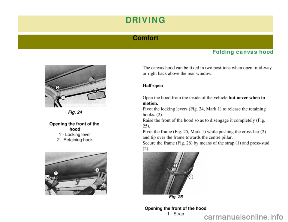
The canvas hood can be fixed in two positions when open: mid-way
or right back above the rear window.
Half-open
Open the hood from the inside of the vehicle but never when in
motion.
Pivot the locking levers (Fig. 24, Mark 1) to release the retaining
hooks. (2)
Raise the front of the hood so as to disengage it completely (Fig.
25).
Pivot the frame (Fig. 25, Mark 1) while pushing the cross-bar (2)
and tip over the frame towards the centre pillar.
Secure the frame (Fig. 26) by means of the strap (1) and press-stud \
(2).
Fig. 24
Opening the front of the hood
1 - Locking lever
2 - Retaining hook
Fig. 26
Opening the front of the hood 1 - Strap