Citroen C1 2015 1.G Owner's Manual
Manufacturer: CITROEN, Model Year: 2015, Model line: C1, Model: Citroen C1 2015 1.GPages: 271, PDF Size: 7.18 MB
Page 151 of 271
149
C1_en_Chap09_info-pratiques_ed01-2015
Changing a bulb
Front lamps
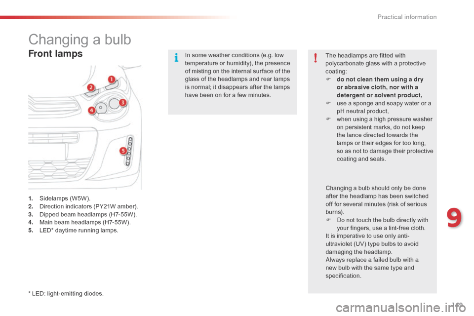
1. Sidelamps (W5W).
2. Direction indicators (PY21W amber).
3.
D
ipped beam headlamps (H7-55W).
4.
M
ain beam headlamps (H7-55W).
5.
L
ED* daytime running lamps. In some weather conditions (e.g. low
temperature or humidity), the presence
of misting on the internal sur face of the
glass of the headlamps and rear lamps
is normal; it disappears after the lamps
have been on for a few minutes.
The headlamps are fitted with
polycarbonate glass with a protective
coating:
F
d
o not clean them using a dr y
or abrasive cloth, nor with a
detergent or solvent product,
F
u
se a sponge and soapy water or a
pH neutral product,
F
w
hen using a high pressure washer
on persistent marks, do not keep
the lance directed towards the
lamps or their edges for too long,
so as not to damage their protective
coating and seals.
Changing a bulb should only be done
after the headlamp has been switched
off for several minutes (risk of serious
burns).
F
D
o not touch the bulb directly with
your fingers, use a lint-free cloth.
It is imperative to use only anti-
ultraviolet (UV) type bulbs to avoid
damaging the headlamp.
Always replace a failed bulb with a
new bulb with the same type and
specification.
* LED: light-emitting diodes.
9
Practical information
Page 152 of 271
150
C1_en_Chap09_info-pratiques_ed01-2015
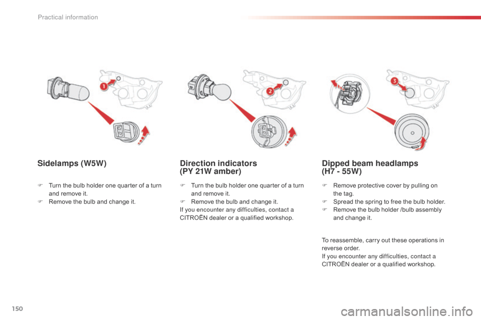
Direction indicators
(PY 21W amber)
Sidelamps (W5W)
F Turn the bulb holder one quarter of a turn
and remove it.
F
R
emove the bulb and change it.
If you encounter any difficulties, contact a
CITROËN dealer or a qualified workshop.
F
T
urn the bulb holder one quarter of a turn
and remove it.
F
R
emove the bulb and change it.
Dipped beam headlamps
(H7 - 55W)
F Remove protective cover by pulling on the tag.
F
S
pread the spring to free the bulb holder.
F
R
emove the bulb holder /bulb assembly
and change it.
To reassemble, carry out these operations in
reverse order.
If you encounter any difficulties, contact a
CITROËN dealer or a qualified workshop.
Practical information
Page 153 of 271
151
C1_en_Chap09_info-pratiques_ed01-2015
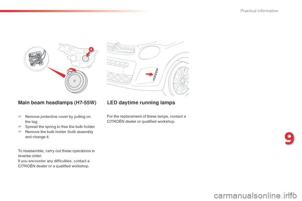
Main beam headlamps (H7-55W)
F Remove protective cover by pulling on the tag.
F
S
pread the spring to free the bulb holder.
F
R
emove the bulb holder /bulb assembly
and change it.
LED daytime running lamps
For the replacement of these lamps, contact a
CITROËN dealer or qualified workshop.
To reassemble, carry out these operations in
reverse order.
If you encounter any difficulties, contact a
CITROËN dealer or a qualified workshop.
9
Practical information
Page 154 of 271
152
C1_en_Chap09_info-pratiques_ed01-2015
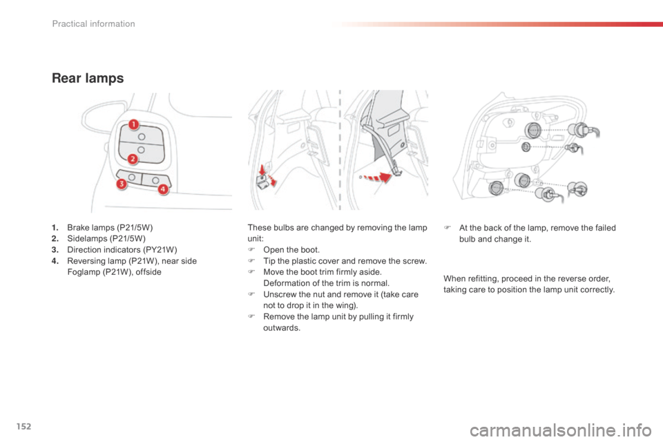
1. Brake lamps (P21/5W)
2. Sidelamps (P21/5W)
3.
D
irection indicators (PY21W)
4.
R
eversing lamp (P21W), near side
F
oglamp (P21W), offside
Rear lamps
These bulbs are changed by removing the lamp
unit:
F
O
pen the boot.
F
T
ip the plastic cover and remove the screw.
F
M
ove the boot trim firmly aside.
D
eformation of the trim is normal.
F
U
nscrew the nut and remove it (take care
not to drop it in the wing).
F
R
emove the lamp unit by pulling it firmly
outwards. F
A t the back of the lamp, remove the failed
bulb and change it.
When refitting, proceed in the reverse order,
taking care to position the lamp unit correctly.
Practical information
Page 155 of 271
153
C1_en_Chap09_info-pratiques_ed01-2015
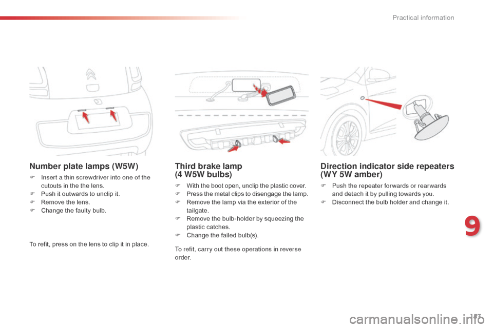
Number plate lamps (W5W)
F Insert a thin screwdriver into one of the cutouts in the the lens.
F
P
ush it outwards to unclip it.
F
R
emove the lens.
F
C
hange the faulty bulb.
Third brake lamp
(4 W5W bulbs)
F With the boot open, unclip the plastic cover.
F P ress the metal clips to disengage the lamp.
F
R
emove the lamp via the exterior of the
tailgate.
F
R
emove the bulb-holder by squeezing the
plastic catches.
F
C
hange the failed bulb(s).
Direction indicator side repeaters
(WY 5W amber)
F Push the repeater for wards or rear wards and detach it by pulling towards you.
F
D
isconnect the bulb holder and change it.
To refit, press on the lens to clip it in place. To refit, carry out these operations in reverse
o r d e r.
9
Practical information
Page 156 of 271
154
C1_en_Chap09_info-pratiques_ed01-2015
Changing a fuse
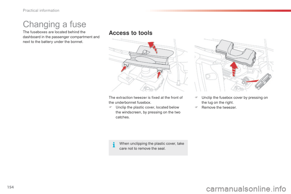
Access to toolsThe fuseboxes are located behind the
dashboard in the passenger compartment and
next to the battery under the bonnet.The extraction tweezer is fixed at the front of
the underbonnet fusebox.
F
U
nclip the plastic cover, located below
the windscreen, by pressing on the two
catches. F
U
nclip the fusebox cover by pressing on
the lug on the right.
F
R
emove the tweezer.
When unclipping the plastic cover, take
care not to remove the seal.
Practical information
Page 157 of 271
155
C1_en_Chap09_info-pratiques_ed01-2015
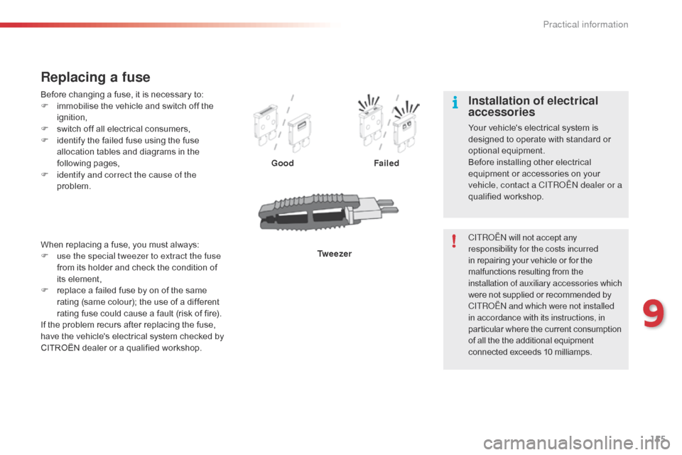
Before changing a fuse, it is necessary to:
F i mmobilise the vehicle and switch off the
ignition,
F
s
witch off all electrical consumers,
F
i
dentify the failed fuse using the fuse
allocation tables and diagrams in the
following pages,
F
i
dentify and correct the cause of the
problem.
Replacing a fuse
Good Failed
Tw e e z e r
When replacing a fuse, you must always:
F
u
se the special tweezer to extract the fuse
from its holder and check the condition of
its element,
F
r
eplace a failed fuse by on of the same
rating (same colour); the use of a different
rating fuse could cause a fault (risk of fire).
If the problem recurs after replacing the fuse,
have the vehicle's electrical system checked by
CITROËN dealer or a qualified workshop. CITROËN will not accept any
responsibility for the costs incurred
in repairing your vehicle or for the
malfunctions resulting from the
installation of auxiliary accessories which
were not supplied or recommended by
CITROËN
and which were not installed
in accordance with its instructions, in
particular where the current consumption
of all the the additional equipment
connected exceeds 10 milliamps.
Installation of electrical
accessories
Your vehicle's electrical system is
designed to operate with standard or
optional equipment.
Before installing other electrical
equipment or accessories on your
vehicle, contact a CITROËN dealer or a
qualified workshop.
9
Practical information
Page 158 of 271
156
C1_en_Chap09_info-pratiques_ed01-2015
Dashboard fuses
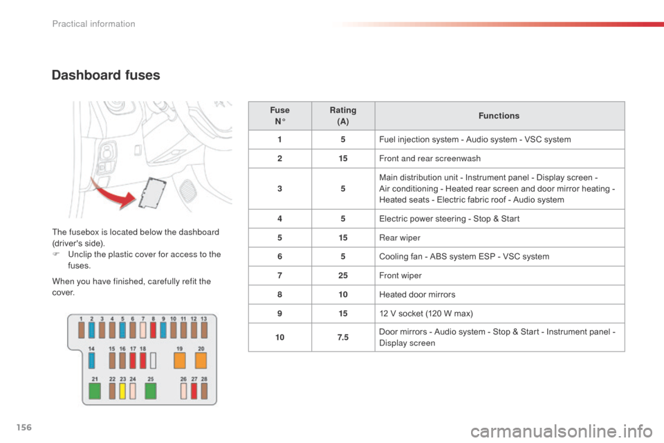
The fusebox is located below the dashboard
(driver's side).
F
U
nclip the plastic cover for access to the
fuses.
When you have finished, carefully refit the
c ove r. Fuse
N° Rating
(A) Functions
1 5Fuel injection system - Audio system - VSC system
2 15Front and rear screenwash
3 5Main distribution unit - Instrument panel - Display screen -
Air conditioning - Heated rear screen and door mirror heating -
Heated seats - Electric fabric roof - Audio system
4 5Electric power steering - Stop & Start
5 15Rear wiper
6 5Cooling fan - ABS system ESP - VSC system
7 25Front wiper
8 10Heated door mirrors
9 1512 V socket (120 W max)
10 7. 5Door mirrors - Audio system - Stop & Start - Instrument panel -
Display screen
Practical information
Page 159 of 271
157
C1_en_Chap09_info-pratiques_ed01-2015
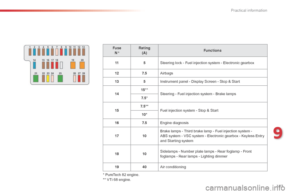
FuseN° Rating
(A) Functions
11 5Steering lock - Fuel injection system - Electronic gearbox
12 7. 5Airbags
13 5Instrument panel - Display Screen - Stop & Start
14 15
**
Steering - Fuel injection system - Brake lamps
7. 5 *
15 7. 5 * *
Fuel injection system - Stop & Start
10*
16 7. 5Engine diagnosis
17 10Brake lamps - Third brake lamp - Fuel injection system -
ABS system - VSC system - Electronic gearbox - Keyless Entry
and Starting system
18 10Sidelamps - Number plate lamps - Rear foglamp - Front
foglamps - Rear lamps - Lighting dimmer
19 40Air conditioning
* PureTech 82 engine.
** VTi 68 engine.
9
Practical information
Page 160 of 271
158
C1_en_Chap09_info-pratiques_ed01-2015
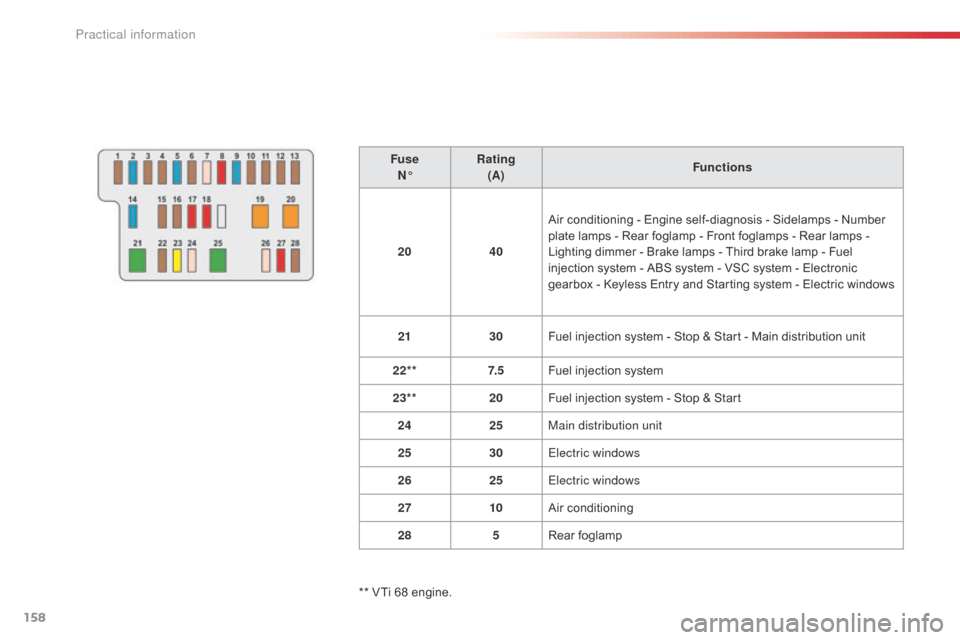
FuseN° Rating
(A) Functions
20 40Air conditioning - Engine self-diagnosis - Sidelamps - Number
plate lamps - Rear foglamp - Front foglamps - Rear lamps
-
Lighting dimmer - Brake lamps - Third brake lamp - Fuel
injection system - ABS system - VSC system - Electronic
gearbox - Keyless Entry and Starting system - Electric windows
21 30Fuel injection system - Stop & Start - Main distribution unit
22** 7. 5Fuel injection system
23** 20Fuel injection system - Stop & Start
24 25Main distribution unit
25 30Electric windows
26 25Electric windows
27 10Air conditioning
28 5Rear foglamp
** VTi 68 engine.
Practical information