warning Citroen C3 PICASSO 2009.5 1.G Owner's Manual
[x] Cancel search | Manufacturer: CITROEN, Model Year: 2009.5, Model line: C3 PICASSO, Model: Citroen C3 PICASSO 2009.5 1.GPages: 198, PDF Size: 9.99 MB
Page 3 of 198
4
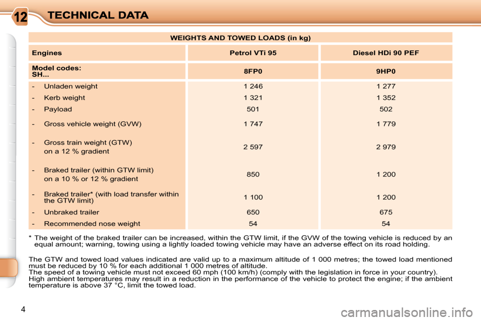
* The weight of the braked trailer can be increased, within the GTW limit, if the GVW of the towing vehicle is reduced by an
equal amount; warning, towing using a lightly loaded to wing vehicle may have an adverse effect on its road holding.
WEIGHTS AND TOWED LOADS (in kg)
Engines
Petrol
VTi 95 Diesel HDi 90 PEF
Model codes:
SH...
8FP0 9HP0
- Unladen weight 1 246 1 277
- Kerb weight 1 321 1 352
- Payload 501 502
- Gross vehicle weight (GVW) 1 747 1 779
- Gross train weight (GTW) on a 12 % gradient 2 597 2 979
- Braked trailer (within GTW limit) on a 10 % or 12 % gradient 850 1 200
- Braked trailer * (with load transfer within the GTW limit) 1 100 1 200
- Unbraked trailer 650 675
- Recommended nose weight 54 54
The GTW and towed load values indicated are valid up to a maximum altitude of 1 000 metres; the towed load mention ed
must be reduced by 10 % for each additional 1 000 metres of a ltitude.
The speed of a towing vehicle must not exceed 60 mph (100 k m/h) (comply with the legislation in force in your country).
High ambient temperatures may result in a reduction in the pe rformance of the vehicle to protect the engine; if the ambient
temperature is above 37 °C, limit the towed load.
Page 4 of 198
i
18
INSTRUMENTS and CONTROLS
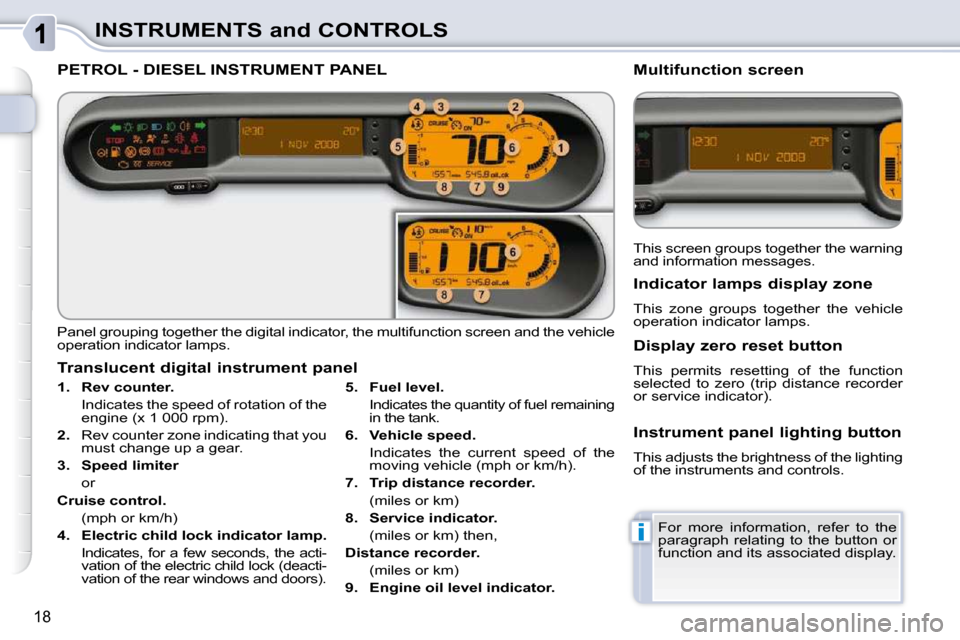
PETROL - DIESEL INSTRUMENT PANEL
Panel grouping together the digital indicator, the multifunction screen and the vehicle
operation indicator lamps.
1. Rev counter.
Indicates the speed of rotation of the engine (x 1 000 rpm).
2. Rev counter zone indicating that you
must change up a gear.
3. Speed limiter
or
Cruise control.
(mph or km/h)
4. Electric child lock indicator lamp.
Indicates, for a few seconds, the acti- vation of the electric child lock (deacti-
vation of the rear windows and doors).
Translucent digital instrument panel
This screen groups together the warning
and information messages.
Multifunction screen
Indicator lamps display zone
This zone groups together the vehicle
operation indicator lamps.
Display zero reset button
This permits resetting of the function
selected to zero (trip distance recorder
or service indicator).
Instrument panel lighting button
This adjusts the brightness of the lighting
of the instruments and controls.
For more information, refer to the
paragraph relating to the button or
function and its associated display.
5. Fuel level.
Indicates the quantity of fuel remaining in the tank.
6. Vehicle speed.
Indicates the current speed of the moving vehicle (mph or km/h).
7. Trip distance recorder.
(miles or km)
8. Service indicator.
(miles or km) then,
Distance recorder.
(miles or km)
9. Engine oil level indicator.
Page 5 of 198
!
19
INSTRUMENTS and CONTROLS Certain warning lamps may come
on in two different modes. Only
by relating the type of lighting to
the operating status of the vehicle
can it be ascertained whether the
situation is normal or whether a
fault has occurred.
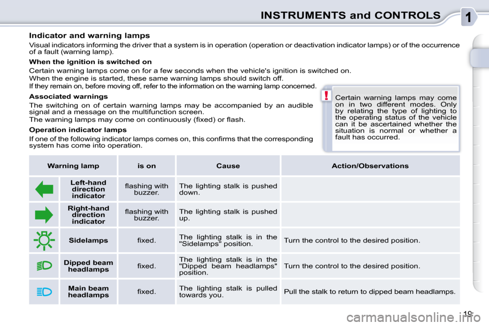
Indicator and warning lamps
Visual indicators informing the driver that a syst
em is in operation (operation or deactivation indic ator lamps) or of the occurrence
of a fault (warning lamp).
Associated warnings
The switching on of certain warning lamps may be accompanied b y an audible
signal and a message on the multifunction screen.
� �T�h�e� �w�a�r�n�i�n�g� �l�a�m�p�s� �m�a�y� �c�o�m�e� �o�n� �c�o�n�t�i�n�u�o�u�s�l�y� �(�fi� �x�e�d�)� �o�r� �fl� �a�s�h�.�
Operation indicator lamps
� �I�f� �o�n�e� �o�f� �t�h�e� �f�o�l�l�o�w�i�n�g� �i�n�d�i�c�a�t�o�r� �l�a�m�p�s� �c�o�m�e�s� �o�n�,� �t�h�i�s� �c�o�n�fi� �r�m�s� �t�h�a�t� �t�h�e� �c�o�r�r�e�s�p�o�n�d�i�n�g�
system has come into operation.
When the ignition is switched on
Certain warning lamps come on for a few seconds when the veh
icle's ignition is switched on.
When the engine is started, these same warning lamps should switch off.
If they remain on, before moving off, refer to the information on the warning lamp concerned.
Warning lamp is on Cause Action/Observations
Left-hand
direction
indicato
r � � �fl� �a�s�h�i�n�g� �w�i�t�h�
buzzer. The lighting stalk is pushed
down.
Right-hand
direction
indicator � � �fl� �a�s�h�i�n�g� �w�i�t�h�
buzzer. The lighting stalk is pushed
up.
Sidelamps � � �fi� �x�e�d�.� � The lighting stalk is in the
"Sidelamps" position. Turn the control to the desired position.
Dipped beam
headlamps � � �fi� �x�e�d�.� � The lighting stalk is in the
"Dipped beam headlamps"
position. Turn the control to the desired position .
Main beam
headlamps � � �fi� �x�e�d�.� � The lighting stalk is pulled
towards you. Pull the stalk to return to dipped beam headlamps.
Page 6 of 198
20
INSTRUMENTS and CONTROLS
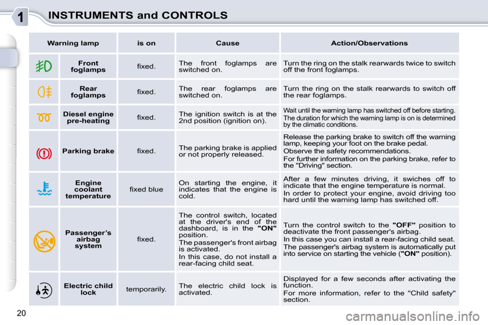
Warning lamp is on Cause Action/Observations
Front
foglamps � � �fi� �x�e�d�.� � The front foglamps are
switched on. Turn the ring on the stalk rearwards twice to switch
off the front foglamps.
Rear
foglamps � � �fi� �x�e�d�.� � The rear foglamps are
switched on. Turn the ring on the stalk rearwards to switch off
the rear foglamps.
Diesel engine
pre-heating � � �fi� �x�e�d�.� � The ignition switch is at the
2 nd position (ignition on). Wait until the warning lamp has switched off befor
e starting.
The duration for which the warning lamp is on is d etermined
by the climatic conditions.
Parking brake � � �fi� �x�e�d�.� � The parking brake is applied
or not properly released. Release the parking brake to switch off the warnin
g
lamp, keeping your foot on the brake pedal.
Observe the safety recommendations.
For further information on the parking brake, refe r to
the "Driving" section.
Engine
coolant
temperature � � �fi� �x�e�d� �b�l�u�e� � On starting the engine, it
indicates that the engine is
cold. After a few minutes driving, it swiches off to
indicate that the engine temperature is normal.
In order to protect your engine, avoid driving too
hard until the warning lamp has switched off.
Passenger’s
airbag
system � �fi� �x�e�d�.� The control switch, located
at the driver's end of the
dashboard, is in the
"
ON
"
position.
The passenger's front airbag
is activated.
In this case, do not install a
rear-facing child seat. Turn the control switch to the
"
OFF
" position to
deactivate the front passenger's airbag.
In this case you can install a rear-facing child se at.
The passenger's airbag system is automatically put
into service on starting the vehicle ( "
ON
" position).
Electric child
lock temporarily. The electric child lock is
activated. Displayed for a few seconds after activating the
function.
For more information, refer to the "Child safety"
section.
Page 7 of 198
21
INSTRUMENTS and CONTROLS
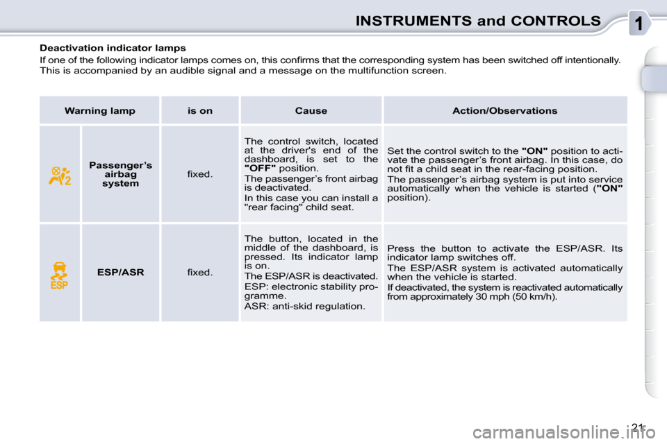
Deactivation indicator lamps
� �I�f� �o�n�e� �o�f� �t�h�e� �f�o�l�l�o�w�i�n�g� �i�n�d�i�c�a�t�o�r� �l�a�m�p�s� �c�o�m�e�s� �o�n�,� �t�h�i�s� �c�o�n�fi� �r�m�s� �t�h�a�t� �t�h�e� �c�o�r�r�e�s�p�o�n�d�i�n�g� �s�y�s�t�e�m� �h�a�s� �b�e�e �n� �s�w�i�t�c�h�e�d� �o�f�f� �i�n�t�e�n�t�i�o�n�a�l�l�y�.� �
This is accompanied by an audible signal and a message on the multifunction screen.
Warning lamp is on Cause Action/Observations
Passenger’s
airbag
system � � �fi� �x�e�d�.� � The control switch, located
at the driver's end of the
dashboard, is set to the
"OFF
" position.
The passenger’s front airbag
is deactivated.
In this case you can install a
"rear facing" child seat. Set the control switch to the
"ON" position to acti-
vate the passenger’s front airbag. In this case, do
�n�o�t� �fi� �t� �a� �c�h�i�l�d� �s�e�a�t� �i�n� �t�h�e� �r�e�a�r�-�f�a�c�i�n�g� �p�o�s�i�t�i�o�n�.�
The passenger’s airbag system is put into service
automatically when the vehicle is started ( "ON"
position).
ESP/ASR � � �fi� �x�e�d�.� � The button, located in the
middle of the dashboard, is
pressed. Its indicator lamp
is on.
The ESP/ASR is deactivated.
ESP: electronic stability pro-
gramme.
ASR: anti-skid regulation. Press the button to activate the ESP/ASR. Its
indicator lamp switches off.
The ESP/ASR system is activated automatically
when the vehicle is started.
If deactivated, the system is reactivated automati
cally
from approximately 30 mph (50 km/h).
Page 8 of 198
!
22
INSTRUMENTS and CONTROLS
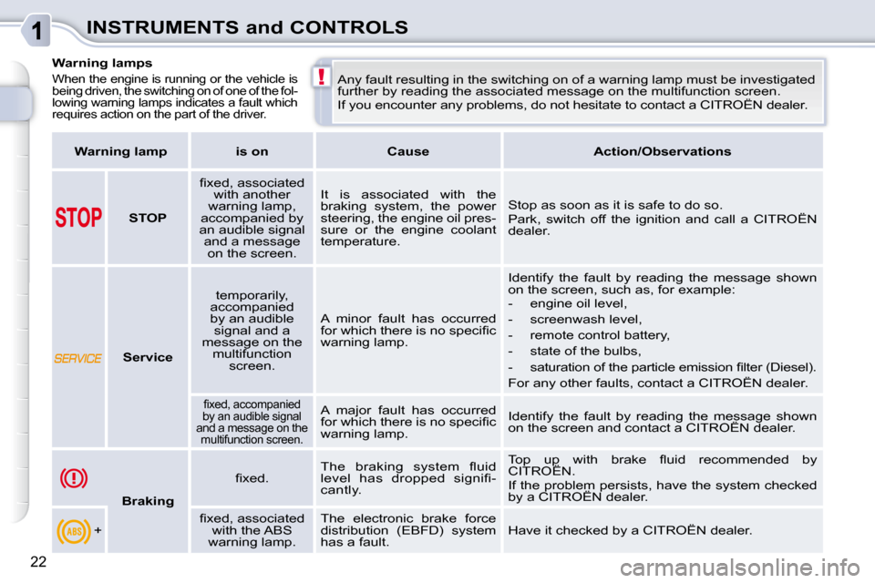
Warning lamps
When the engine is running or the vehicle is
being driven, the switching on of one of the fol-
lowing warning lamps indicates a fault which
requires action on the part of the driver. Any fault resulting in the switching on of a warning lamp must be investigated
further by reading the associated message on the multifunction screen.
If you encounter any problems, do not hesitate to contact a CITROËN dealer.
Warning lamp is on Cause Action/Observations
STOP � � �fi� �x�e�d�,� �a�s�s�o�c�i�a�t�e�d�
with another
warning lamp,
accompanied by
an audible signal and a message on the screen. It is associated with the
braking system, the power
steering, the engine oil pres-
sure or the engine coolant
temperature.
Stop as soon as it is safe to do so.
Park, switch off the ignition and call a CITROËN
dealer.
Service temporarily,
accompanied
by an audible signal and a
message on the multifunction screen. A minor fault has occurred
�f�o�r� �w�h�i�c�h� �t�h�e�r�e� �i�s� �n�o� �s�p�e�c�i�fi� �c�
warning lamp. Identify the fault by reading the message shown
on the screen, such as, for example:
- engine oil level,
- screenwash level,
- remote control battery,
- state of the bulbs,
� � �-� � �s�a�t�u�r�a�t�i�o�n� �o�f� �t�h�e� �p�a�r�t�i�c�l�e� �e�m�i�s�s�i�o�n� �fi� �l�t�e�r� �(�D�i�e
�s�e�l�)�.� �
For any other faults, contact a CITROËN dealer.
� � �fi� �x�e�d�,� �a�c�c�o�m�p�a�n�i�e�d�
by an audible signal
and a message on the multifunction screen. A major fault has occurred
�f�o�r� �w�h�i�c�h� �t�h�e�r�e� �i�s� �n�o� �s�p�e�c�i�fi� �c�
warning lamp. Identify the fault by reading the message shown
on the screen and contact a CITROËN dealer.
Braking � � �fi� �x�e�d�.� �
� �T�h�e� �b�r�a�k�i�n�g� �s�y�s�t�e�m� �fl� �u�i�d�
�l�e�v�e�l� �h�a�s� �d�r�o�p�p�e�d� �s�i�g�n�i�fi� �-
cantly. � �T�o�p� �u�p� �w�i�t�h� �b�r�a�k�e� �fl� �u�i�d� �r�e�c�o�m�m�e�n�d�e�d� �b�y�
CITROËN.
If the problem persists, have the system checked
by a CITROËN dealer.
+ � � �fi� �x�e�d�,� �a�s�s�o�c�i�a�t�e�d�
with the ABS
warning lamp. The electronic brake force
distribution (EBFD) system
has a fault.
Have it checked by a CITROËN dealer.
Page 9 of 198
23
INSTRUMENTS and CONTROLS
Warning lamp is on Cause Action/Observations
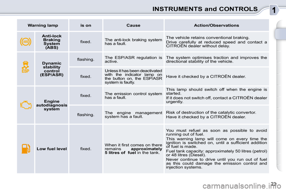
Anti-lock
Braking System (ABS) � � �fi� �x�e�d�.� �
The anti-lock braking system
has a fault. The vehicle retains conventional braking.
Drive carefully at reduced speed and contact a
CITROËN dealer without delay.
Dynamic
stability control
(ESP/ASR) � � �fl� �a�s�h�i�n�g�.� �
The ESP/ASR regulation is
active. The system optimises traction and improves the
directional stability of the vehicle.
� � �fi� �x�e�d�.� � Unless it has been deactivated
with the indicator lamp on
the button on, the ESP/ASR
system is faulty. Have it checked by a CITROËN dealer.
Engine
autodiagnosis system � � �fi� �x�e�d�.� �
The emission control system
has a fault. This lamp should switch off when the engine is
started.
If it does not switch off, contact a CITROËN dealer
urgently.
� � �fl� �a�s�h�i�n�g�.� � The engine management
system has a fault. Risk of destruction of the catalytic convertor.
Have it checked by a CITROËN dealer.
Low fuel level � � �fi� �x�e�d�.� � � �W�h�e�n� �i�t� �fi� �r�s�t� �c�o�m�e�s� �o�n� �t�h�e�r�e�
remains
approximately
5 litres of fuel in the tank. You must refuel as soon as possible to avoid
running out of fuel.
This warning lamp will come on every time the
�i�g�n�i�t�i�o�n� �i�s� �s�w�i�t�c�h�e�d� �o�n�,� �u�n�t�i�l� �a� �s�u�f�fi� �c�i�e�n�t� �a�d�d�i�t�i�o�n�
of fuel is made.
Fuel tank capacity: approximately 50 litres (petrol)
or 48 litres (Diesel).
Never continue to drive until you run out of fuel
as this could damage the emission control and
injection systems.
Page 10 of 198
INSTRUMENTS and CONTROLS
Warning lamp is on Cause Action/Observations
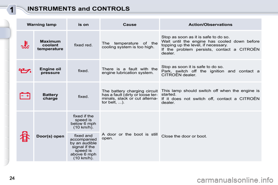
Maximum
coolant
temperature � � �fi� �x�e�d� �r�e�d�.� �
The temperature of the
cooling system is too high. Stop as soon as it is safe to do so.
Wait until the engine has cooled down before
topping up the level, if necessary.
If the problem persists, contact a CITROËN
dealer.
Engine oil
pressure � � �fi� �x�e�d�.� � There is a fault with the
engine lubrication system. Stop as soon it is safe to do so.
Park, switch off the ignition and contact a
CITROËN dealer.
Battery
charge � � �fi� �x�e�d�.� � The battery charging circuit
has a fault (dirty or loose ter-
minals, slack or cut alterna-
tor belt, ...). This lamp should switch off when the engine is
started.
If it does not switch off, contact a CITROËN
dealer.
Door(s) open � � �fi� �x�e�d� �i�f� �t�h�e�
speed is
below 6 mph (10 km/h).
A door or the boot is still
open. Close the door or boot.
� � �fi� �x�e�d� �a�n�d�
accompanied
by an audible signal if the speed is
above 6 mph (10 km/h).
Page 11 of 198
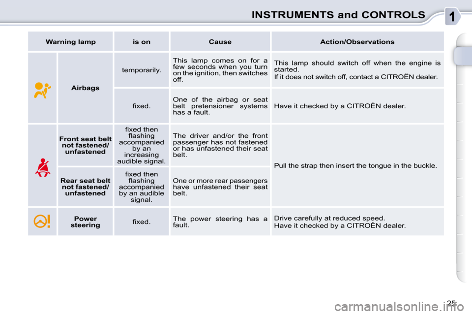
25
INSTRUMENTS and CONTROLS
Warning lamp is on Cause Action/Observations
Airbags temporarily.
This lamp comes on for a
few seconds when you turn
on the ignition, then switches
off. This lamp should switch off when the engine is
started.
If it does not switch off, contact a CITROËN deale
r.
� � �fi� �x�e�d�.� � One of the airbag or seat
belt pretensioner systems
has a fault. Have it checked by a CITROËN dealer.
Front seat belt
not fastened/ unfastened � � �fi� �x�e�d� �t�h�e�n�
�fl� �a�s�h�i�n�g�
accompanied by an
increasing
audible signal. The driver and/or the front
passenger has not fastened
or has unfastened their seat
belt.
Pull the strap then insert the tongue in the buckl e.
Rear seat belt
not fastened/ unfastened � � �fi� �x�e�d� �t�h�e�n�
�fl� �a�s�h�i�n�g�
accompanied
by an audible signal.
One or more rear passengers have unfastened their seat
belt.
Power
steering � �fi� �x�e�d�.� The power steering has a
fault. Drive carefully at reduced speed.
Have it checked by a CITROËN dealer.
Page 14 of 198
i
28
INSTRUMENTS and CONTROLS
The level read will only be correct if
the vehicle is on level ground and
the engine has been off for more
than 15 minutes.
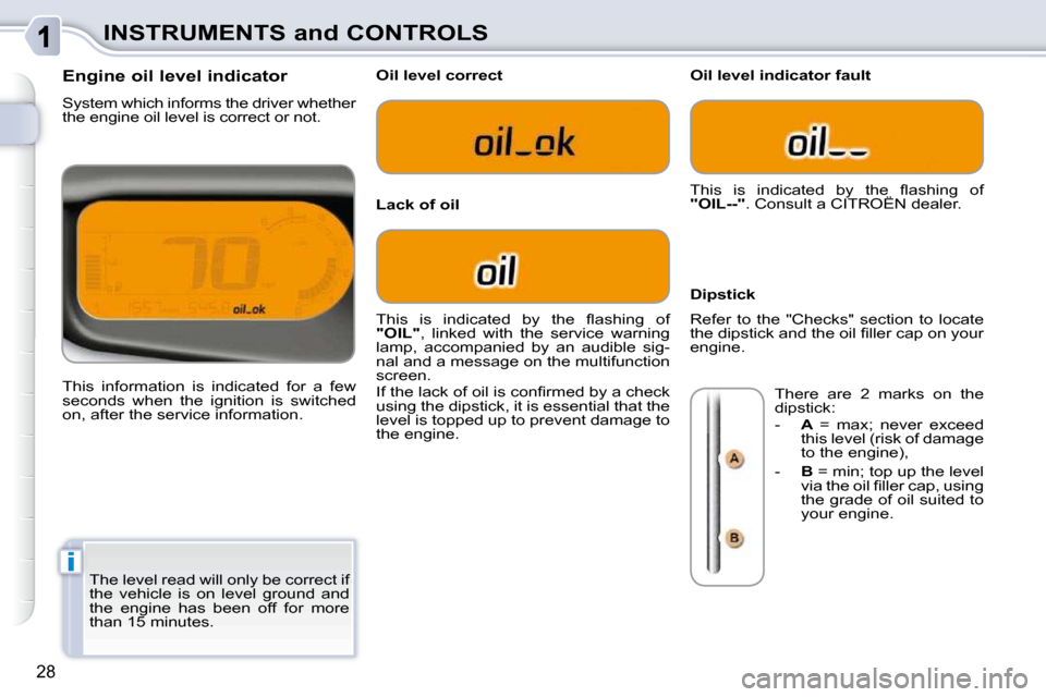
Engine oil level indicator
System which informs the driver whether
the engine oil level is correct or not.
This information is indicated for a few
seconds when the ignition is switched
on, after the service information.
Oil level correct
Lack of oil
Oil level indicator fault
Dipstick
� �T�h�i�s� �i�s� �i�n�d�i�c�a�t�e�d� �b�y� �t�h�e� �fl� �a�s�h�i�n�g� �o�f�
"OIL" , linked with the service warning
lamp, accompanied by an audible sig-
nal and a message on the multifunction
screen.
� �I�f� �t�h�e� �l�a�c�k� �o�f� �o�i�l� �i�s� �c�o�n�fi� �r�m�e�d� �b�y� �a� �c�h�e�c�k�
using the dipstick, it is essential that the
level is topped up to prevent damage to
the engine. � �T�h�i�s� �i�s� �i�n�d�i�c�a�t�e�d� �b�y� �t�h�e� �fl� �a�s�h�i�n�g� �o�f�
"OIL--" . Consult a CITROËN dealer.
Refer to the "Checks" section to locate
�t�h�e� �d�i�p�s�t�i�c�k� �a�n�d� �t�h�e� �o�i�l� �fi� �l�l�e�r� �c�a�p� �o�n� �y�o�u�r�
engine. There are 2 marks on the
dipstick:
- A = max; never exceed
this level (risk of damage
to the engine),
- B = min; top up the level
�v�i�a� �t�h�e� �o�i�l� �fi� �l�l�e�r� �c�a�p�,� �u�s�i�n�g�
the grade of oil suited to
your engine.