boot CITROEN C4 2023 Owner's Manual
[x] Cancel search | Manufacturer: CITROEN, Model Year: 2023, Model line: C4, Model: CITROEN C4 2023Pages: 292, PDF Size: 7.79 MB
Page 141 of 292
139
Driving
6The parking sensors are deactivated while the
Park Assist function is measuring a space.
For more information on the Park Assist
function, refer to the corresponding section.
When starting the vehicle, the graphic
and audible aids are only available after
the touch screen has started up.
Operating limits
If the boot is heavily loaded, the vehicle may tilt,
affecting distance measurements.
Malfunction
In the event of a malfunction when
changing into reverse gear, these
warning lamps light up on the instrument panel,
accompanied by the display of a message and
an audible signal (short beep).
Have it checked by a CITROËN dealer or a
qualified workshop.
Reversing camera
For more information, refer to the
General recommendations on the use
of driving and manoeuvring aids .
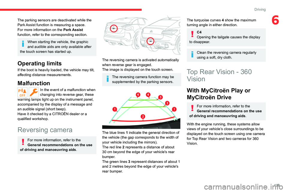
The reversing camera is activated automatically
when reverse gear is engaged.
The image is displayed on the touch screen.
The reversing camera function may be
supplemented by the parking sensors.
The blue lines 1 indicate the general direction of
the vehicle (the gap corresponds to the width of
your vehicle including the mirrors).
The red line 2 represents a distance of about
30
cm beyond the edge of your vehicle's rear
bumper.
The green lines 3 represent distances of about 1
and 2 metres beyond the edge of your vehicle's
rear bumper.
The turquoise curves 4 show the maximum
turning angle in either direction.
C4
Opening the tailgate causes the display
to disappear.
Clean the reversing camera regularly
using a soft, dry cloth.
Top Rear Vision - 360 Vision
With MyCitroën Play or
MyCitroën Drive
For more information, refer to the
General recommendations on the use
of driving and manoeuvring aids .
With the engine running, these systems allow
views of your vehicle’s close surroundings to be
displayed on the touch screen using one camera
for Top Rear Vision and two cameras for 360
Vision.
Page 142 of 292
140
Driving
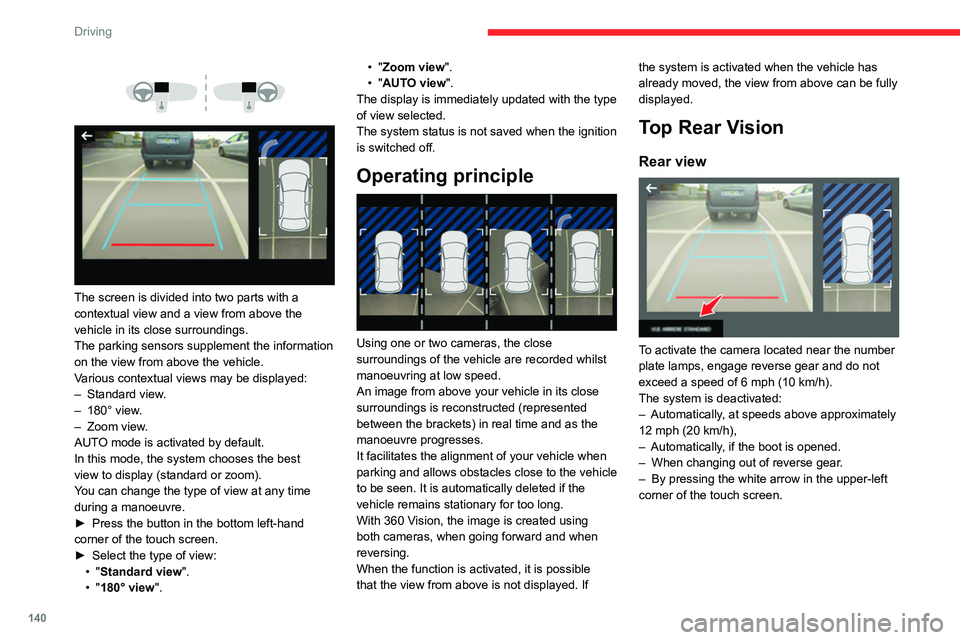
The screen is divided into two parts with a
contextual view and a view from above the
vehicle in its close surroundings.
The parking sensors supplement the information
on the view from above the vehicle.
Various contextual views may be displayed:
–
Standard view
.
–
180° view
.
–
Zoom view
.
AUTO mode is activated by default.
In this mode, the system chooses the best
view
to display (standard or zoom).
You can change the type of view at any time
during a manoeuvre.
►
Press the button in the bottom left-hand
corner of the touch screen.
►
Select the type of view:
•
"Standard view".
•
"180° view". •
"Zoom view".
• "AUTO view".
The display is immediately updated with the type
of view selected.
The system status is not saved when the ignition
is switched off.
Operating principle
Using one or two cameras, the close
surroundings of the vehicle are recorded whilst
manoeuvring at low speed.
An image from above your vehicle in its close
surroundings is reconstructed (represented
between the brackets) in real time and as the
manoeuvre progresses.
It facilitates the alignment of your vehicle when
parking and allows obstacles close to the vehicle
to be seen. It is automatically deleted if the
vehicle remains stationary for too long.
With 360 Vision, the image is created using
both cameras, when going forward and when
reversing.
When the function is activated, it is possible
that the view from above is not displayed. If the system is activated when the vehicle has
already moved, the view from above can be fully
displayed.
Top Rear Vision
Rear view
To activate the camera located near the number
plate lamps, engage reverse gear and do not
exceed a speed of
6 mph (10 km/h).
The system is deactivated:
–
Automatically
, at speeds above approximately
12 mph (20
km/h),
–
Automatically
, if the boot is opened.
–
When changing out of reverse gear
.
–
By pressing the white arrow in the upper-left
corner of the touch screen.
Page 151 of 292
149
Driving
6The images from the camera(s) displayed on the touch screen may be
distorted by the terrain.
In shady areas, or in inadequate sunlight
or lighting conditions, the image may be
darkened and with lower contrast.
The manoeuvre can be permanently interrupted
at any time, either by the driver or automatically
by the system.
Interruption by the driver can be done by:
–
taking over control of the steering.
–
activating the direction indicator lamps on the
opposite side to that of the manoeuvre.
–
unfastening the seat belt.
–
switching off the ignition.
The manoeuvre is automatically interrupted by
the system in the following cases:
–
vehicle exceeding the speed limit of
5
mph (7 km/h) during parking space entry
manoeuvres, or 3
mph (5 km/h) during parking
space exit manoeuvres.
–
activation of anti-slip regulation on a slippery
road.
–
opening of a door or the boot.
–
engine stall.
–
system malfunction.
–
after 10 manoeuvres to enter or exit a parallel
parking space and after 7 manoeuvres to enter a
parking bay
.
Interrupting the manoeuvre automatically
deactivates the function. Depending on audio equipment, the manoeuvre
symbol is displayed in red, accompanied by the
"Manoeuvre cancelled" message on the touch
screen.
A message prompts the driver to take back
control of the vehicle.
The function is deactivated after a few seconds
and returns to the initial display.
Depending on audio equipment, this
indicator lamp goes off.
End of the parking space entry or exit
manoeuvre
The vehicle stops as soon as the manoeuvre is
completed.
Depending on audio equipment, the manoeuvre
symbol is displayed in red, accompanied by the
message "Manoeuvre completed" on the touch
screen.
Depending on audio equipment, when the
function is deactivated, this indicator lamp
goes off, accompanied by an audible signal.
When entering a parking space, the driver may
be required to complete the manoeuvre.
Operating limits
– The system may suggest an inappropriate
parking space (parking prohibited, work in
progress with damaged road surface, location
alongside a ditch, etc.).
–
The system may indicate that a space has
been found but will not offer it because of a fixed
obstacle on the opposite side of the manoeuvre,
which would not allow the vehicle to follow a
trajectory required for parking.
–
The system may indicate that a space has
been found but the manoeuvre will not be
triggered, because the width of the lane is
insufficient.
–
The system is not designed for performing the
parking manoeuvre on a sharp bend.
–
The system does not detect spaces that
are much larger than the vehicle itself or that
are delimited by obstacles that are too low
(pavements, studs, etc.) or too thin (trees, posts,
wire fences, etc.).
–
If the boot is heavily loaded, the tilt of the
vehicle towards the rear may interfere with the
distance measurements.
Do not use the function under the
following exterior conditions:
–
Alongside a soft shoulder (e.g. ditch) or
quay or on the edge of a drop.
–
When the road surface is slippery (e.g. ice).
If any of the following malfunctions
occurs, do not use the system:
–
If a tyre is under-inflated.
–
If one of the bumpers is damaged.
–
If one of the cameras is faulty
.
Page 164 of 292
162
Practical information
For domestic or accelerated charging
Before charging
Depending on the context:
►
Have a professional check that the
electrical system to be used complies with
applicable standards and is compatible with
the vehicle.
►
Have a professional electrician install
a dedicated domestic power socket or
accelerated charging unit (W
allbox)
compatible with the vehicle.
You should preferably use the charging cable
available as an accessory.
For more information, contact a CITROËN
dealer or a qualified workshop.
During charging
While charging is in progress, unlocking
the vehicle will cause the charging to stop.
If no action is taken on one of the openings
(door or boot) or on the charging nozzle, the
vehicle will lock again after 30 seconds and
charging will resume automatically.
Never work under the bonnet:
–
Some areas remain very hot, even an hour
after charging ends - risk of burns!
–
The fan may start at any time - risk of cuts
or strangulation!
After charging
Check that the charging flap is closed.
Do not leave the cable connected to the
domestic power socket - risk of short-circuit
or electrocution in the event of contact with or
immersion in water!
For superfast charging
Before charging
Check that the fast public charging
station and its charging cable are compatible
with the vehicle.
If the exterior temperature is below:
–
0°C, charging times may be extended.
–
-20°C, charging is still possible, but
charging times may be extended even further
(the battery has to be heated first).
After charging
Check that the charging flap is closed.
Connection
► Before charging, check that the drive selector
is in mode P, otherwise charging is not possible.
►
Open the charging flap by pressing the
push-button, and check that there are no foreign
bodies on the charging connector
.
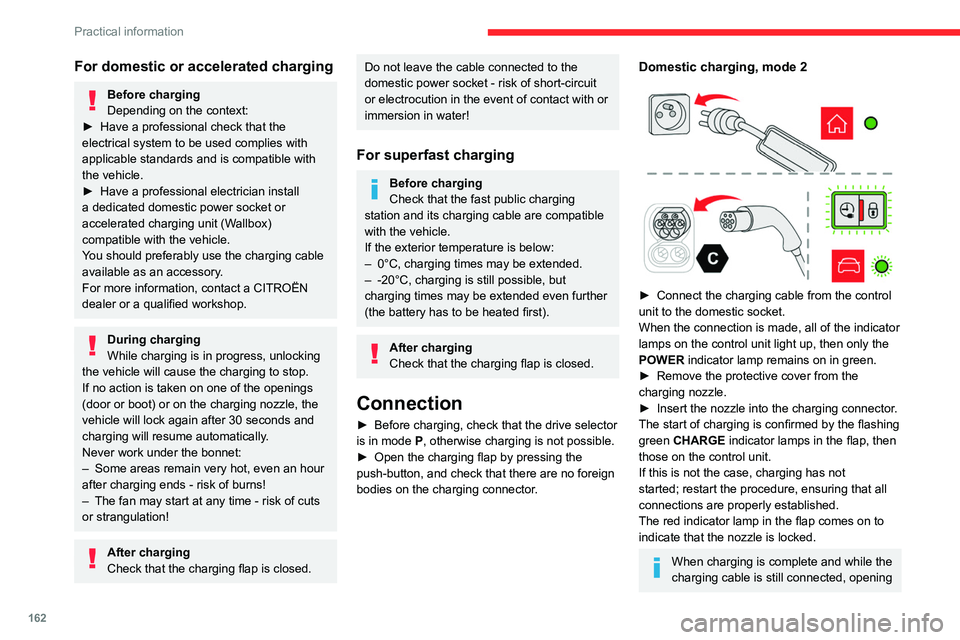
Domestic charging, mode 2
► Connect the charging cable from the control
unit to the domestic socket.
When the connection is made, all of the indicator
lamps on the control unit light up, then only the
POWER
indicator lamp remains on in green.
►
Remove the protective cover from the
charging nozzle.
►
Insert the nozzle into the charging connector
.
The start of charging is confirmed by the flashing
green CHARGE indicator lamps in the flap, then
those on the control unit.
If this is not the case, charging has not
started; restart the procedure, ensuring that all
connections are properly established.
The red indicator lamp in the flap comes on to
indicate that the nozzle is locked.
When charging is complete and while the
charging cable is still connected, opening
Page 167 of 292

165
Practical information
7It is therefore not possible to tow a trailer or
caravan.
Towing device with quickly detachable towball
Presentation
No tools are required to install or remove this
genuine towing device.
1. Carrier
2. Protective plug
3. Connection socket
4. Safety eye
5. Detachable towball
6. Locking/unlocking wheel
7. Security key lock
8. Label to note the key references
A. Locked position (the green marks are
opposite each other); the wheel is in contact
with the towball (no gap).
B. Unlocked position (red mark opposite the green mark); the wheel is no longer
in contact with the towball (gap of around
5
mm).
Affix the enclosed label in a clearly visible location, close to the carrier or in the
boot.
Trailers with LED lamps are not compatible with the wiring harness of this
device.
To ensure complete safety while driving with a Towing device , refer to the
corresponding section.
Before each use
Verify that the towball is correctly fitted,
checking the follow points:
–
The green mark on the wheel is in line with
the green mark on the towball.
–
The wheel is in contact with the towball
(position A
).
–
The security key lock is closed and the
key removed; the wheel can no longer be
operated.
–
The towball must not be able to move in
its carrier; test by attempting to shake it with
your hand.
If the towball is not locked, the trailer can
become detached - risk of an accident!
During use
Never release the locking system with a
trailer or load carrier on the towball.
Never exceed the maximum authorised
weight for the vehicle - the Gross Train
Weight or GTW.
Always comply with the maximum authorised
load on the towing device: if it is exceeded,
this device may become detached from the
vehicle - risk of an accident!
Before driving, check the headlamp height
adjustment and check that the lamps on the
trailer operate correctly.
For more information on Headlamp height
adjustment, refer to the corresponding
section.
Page 182 of 292
180
In the event of a breakdown
Warning triangle
This reflective and dismantable device is to be
installed on the side of the road when a vehicle
is broken down or damaged.
Before getting out of the vehicle
Turn on the hazard warning lamps, then
put on the safety vest to assemble and install
the triangle.
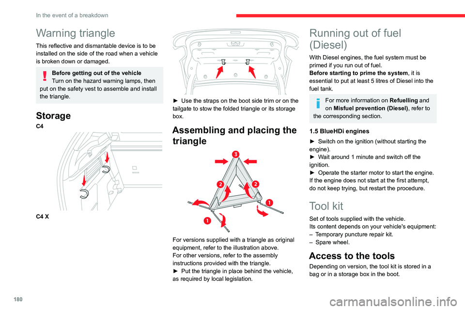
Storage
C4
C4 X
► Use the straps on the boot side trim or on the
tailgate to stow the folded triangle or its storage
box.
Assembling and placing the triangle
For versions supplied with a triangle as original
equipment, refer to the illustration above.
For other versions, refer to the assembly
instructions provided with the triangle.
►
Put the triangle in place behind the vehicle,
as required by local legislation.
Running out of fuel
(Diesel)
With Diesel engines, the fuel system must be
primed if you run out of fuel.
Before starting to prime the system, it is
essential to put at least 5 litres of Diesel into the
fuel tank.
For more information on Refuelling and
on Misfuel prevention (Diesel), refer to
the corresponding section.
1.5 BlueHDi engines
► Switch on the ignition (without starting the
engine).
►
W
ait around 1 minute and switch off the
ignition.
►
Operate the starter motor to start the engine.
If the engine does not start at the first attempt,
do not keep trying, but restart the procedure.
Tool kit
Set of tools supplied with the vehicle.
Its content depends on your vehicle's equipment:
–
T
emporary puncture repair kit.
–
Spare wheel.
Access to the tools
Depending on version, the tool kit is stored in a
bag or in a storage box in the boot.
Page 186 of 292
184
In the event of a breakdown
contact a CITROËN dealer or a qualified
workshop for assistance.
►
Once the correct pressure is reached, put the
switch in position " O
".
►
Remove the kit and stow it.
►
Refit the cap on the valve.
Spare wheel
Visit this link to view explanatory videos:
http://q-r.to/bagGl9
For more information on the Tool kit,
refer to the corresponding section.
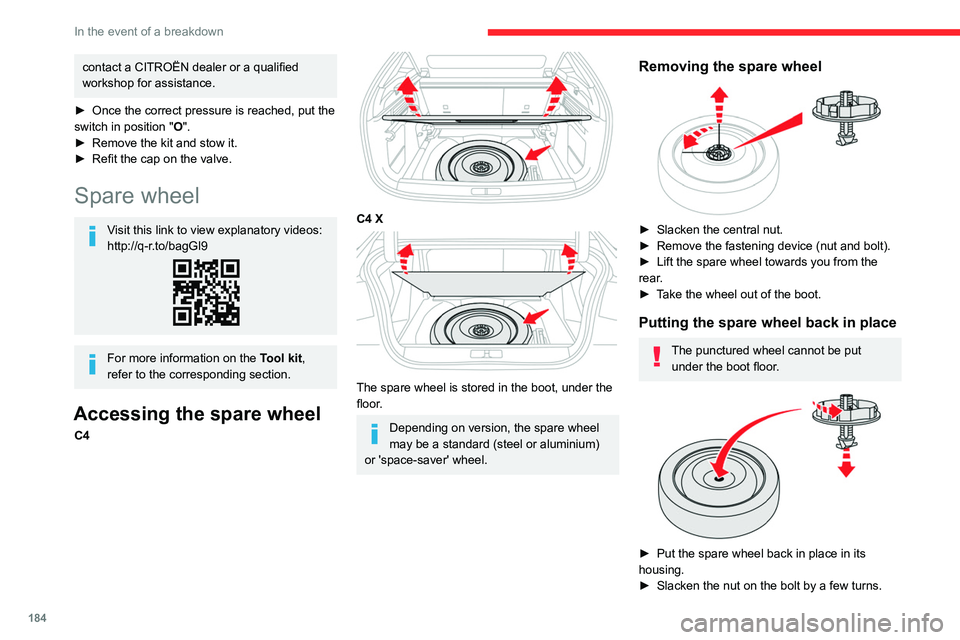
Accessing the spare wheel
C4
C4 X
The spare wheel is stored in the boot, under the
floor.
Depending on version, the spare wheel
may be a standard (steel or aluminium)
or 'space-saver' wheel.
Removing the spare wheel
► Slacken the central nut.
► Remove the fastening device (nut and bolt).
►
Lift the spare wheel towards you from the
rear
.
►
T
ake the wheel out of the boot.
Putting the spare wheel back in place
The punctured wheel cannot be put under the boot floor.
► Put the spare wheel back in place in its
housing.
►
Slacken the nut on the bolt by a few turns.
Page 192 of 292
190
In the event of a breakdown
3.Direction indicators (LED)
4. Foglamp (P21W) or Reversing lamp (W16W)
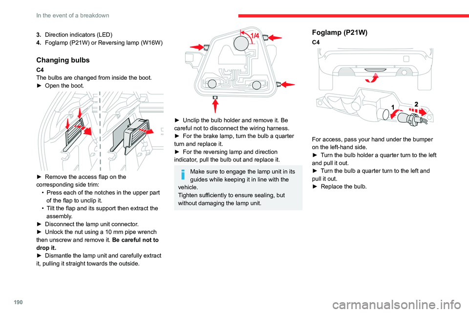
Changing bulbs
C4
The bulbs are changed from inside the boot.
►
Open the boot.
► Remove the access flap on the
corresponding side trim: •
Press each of the notches in the upper part
of the flap to unclip it.
•
T
ilt the flap and its support then extract the
assembly.
►
Disconnect the lamp unit connector
.
►
Unlock the nut using a 10 mm pipe wrench
then unscrew and remove it. Be careful not to
drop it.
►
Dismantle the lamp unit and carefully extract
it, pulling it straight towards the outside.
► Unclip the bulb holder and remove it. Be
careful not to disconnect the wiring harness.
►
For the brake lamp, turn the bulb a quarter
turn and replace it.
►
For the reversing lamp and direction
indicator
, pull the bulb out and replace it.
Make sure to engage the lamp unit in its
guides while keeping it in line with the
vehicle.
Tighten sufficiently to ensure sealing, but
without damaging the lamp unit.
Foglamp (P21W)
C4
For access, pass your hand under the bumper
on the left-hand side.
►
T
urn the bulb holder a quarter turn to the left
and pull it out.
►
T
urn the bulb a quarter turn to the left and
pull it out.
►
Replace the bulb.
Page 195 of 292
193
In the event of a breakdown
8the booster (or to an earth point on the assisting
vehicle).
►
Connect the other end of the green or black
cable to the (-) terminal of flat battery
A.
►
Start the engine on the assisting vehicle and
leave it running for a few minutes.
►
Operate the starter on the broken down
vehicle and let the engine run.
If the engine does not start immediately
, switch
off the ignition and wait a few moments before
trying again.
►
W
ait for it to return to idle.
►
Disconnect the jump leads in reverse order.
►
Refit the plastic cover to the (+) terminal, if
the vehicle has one.
►
Allow the engine to run for at least
30
minutes, with the vehicle stationary, so that
the battery reaches an adequate state of charge.
Driving immediately without having
reached a sufficient level of charge may
affect some of the vehicle's functions (e.g.
Stop & Start).
Charging the battery using a
battery charger
For optimum service life of the battery, it is
essential to maintain an adequate state of
charge.
In some circumstances, it may be necessary to
charge the battery:
– When using the vehicle mainly for short
journeys.
–
If the vehicle is to be taken off the road for
several weeks.
Contact a CITROËN dealer or a qualified
workshop.
To charge the vehicle's battery yourself, use only a charger compatible with
lead-acid batteries with a nominal voltage of
12
V.
Follow the instructions provided by the
manufacturer of the charger.
Never reverse polarities.
It is not necessary to disconnect the
battery.
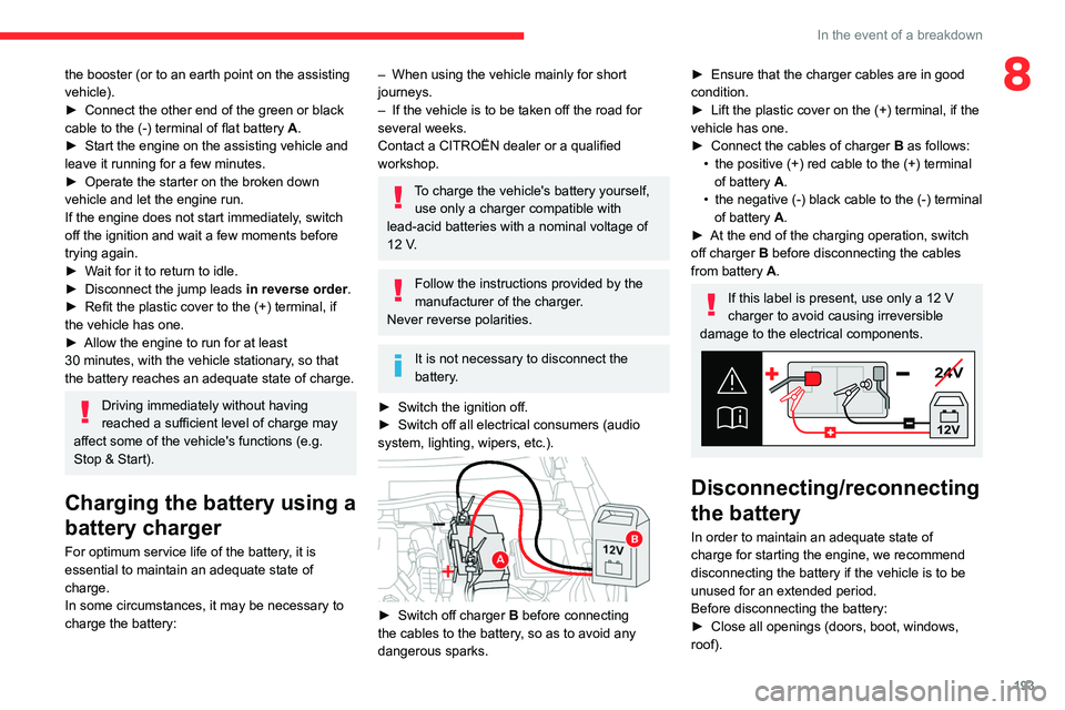
►
Switch the ignition off.
►
Switch off all electrical consumers (audio
system, lighting, wipers, etc.).
► Switch off charger B before connecting
the cables to the battery, so as to avoid any
dangerous sparks.
► Ensure that the charger cables are in good
condition.
►
Lift the plastic cover on the (+) terminal, if the
vehicle has one.
►
Connect the cables of charger B
as follows:
•
the positive (+) red cable to the (+) terminal
of battery
A.
•
the negative (-) black cable to the (-) terminal
of battery
A.
►
At the end of the charging operation, switch
off charger B
before disconnecting the cables
from battery A.
If this label is present, use only a 12 V
charger to avoid causing irreversible
damage to the electrical components.
24V
12V
Disconnecting/reconnecting
the battery
In order to maintain an adequate state of
charge for starting the engine, we recommend
disconnecting the battery if the vehicle is to be
unused for an extended period.
Before disconnecting the battery:
►
Close all openings (doors, boot, windows,
roof).
Page 198 of 292
196
In the event of a breakdown
Accessing the tools
The towing eye is stored with the tool kit in the
boot.
For more information on accessing the Tool kit,
refer to the corresponding section.
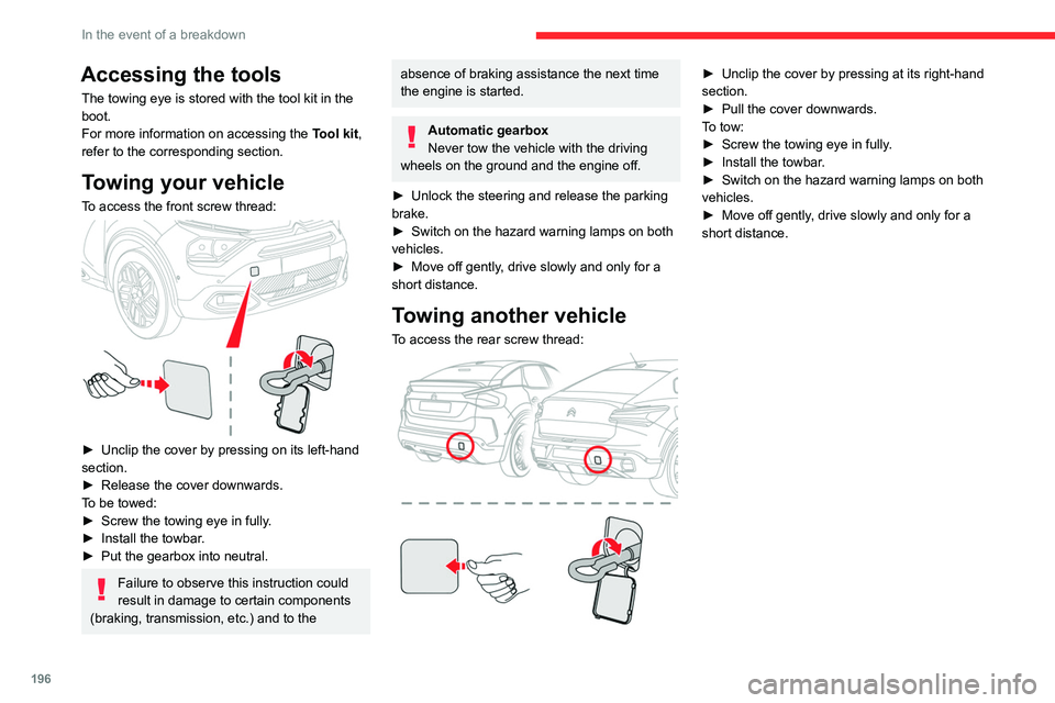
Towing your vehicle
To access the front screw thread:
► Unclip the cover by pressing on its left-hand
section.
►
Release the cover downwards.
T
o be towed:
►
Screw the towing eye in fully
.
►
Install the towbar
.
►
Put the gearbox into neutral.
Failure to observe this instruction could
result in damage to certain components
(braking, transmission, etc.) and to the
absence of braking assistance the next time
the engine is started.
Automatic gearbox
Never tow the vehicle with the driving
wheels on the ground and the engine off.
►
Unlock the steering and release the parking
brake.
►
Switch on the hazard warning lamps on both
vehicles.
►
Move off gently
, drive slowly and only for a
short distance.
Towing another vehicle
To access the rear screw thread:
► Unclip the cover by pressing at its right-hand
section.
►
Pull the cover downwards.
T
o tow:
►
Screw the towing eye in fully
.
►
Install the towbar
.
►
Switch on the hazard warning lamps on both
vehicles.
►
Move off gently
, drive slowly and only for a
short distance.