Citroen C4 CACTUS 2016 1.G Owner's Manual
Manufacturer: CITROEN, Model Year: 2016, Model line: C4 CACTUS, Model: Citroen C4 CACTUS 2016 1.GPages: 308, PDF Size: 7.96 MB
Page 201 of 308

199
Daytime running lamps /
S idelamps (LEDs)
For the replacement of the light-emitting d
iodes (LEDs), contact a CITROËN dealer or a
q
ualified
w
orkshop. F
D isconnect the bulb connector.
F
R
emove the bulb and change it.
Dipped beam headlamps
F Remove the protective cover by pulling t
he tab.
F
T
ake the connector and bulb holder, then
l
ift the assembly upwards to unclip it.
F
R
emove the assembly of connector and
b
ulb holder. To
reassemble, carry out these operations in
r
everse order, positioning the alignment lug
at the top .
8
In the event of a breakdown
Page 202 of 308

200
Main beam headlamps
F Remove the protective cover by pulling t
he tab.
F
D
isconnect the bulb connector (do not
r
emove
t
he
e
arth
c
onnector
lo
cated
belo
w).
F
P
ush on the spring, then move it towards
t
he middle of the vehicle to release
t
he bulb.
F
R
emove the bulb and change it.
Direction indicators
Amber coloured bulbs, such as the direction indicators, must be replaced
w
ith bulbs of identical specifications
a
nd colour.
Rapid
flashing
of
the
direction
indicator
w
arning
lamp
(right
or
left)
indicates
the
f
ailure
of
a
bulb
on
that
side.
F
T
urn
the
bulb
holder
an
eighth
of
a
turn
a
nti-clockwise
and
extract
it.
F
R
emove
the
bulb
and
change
it.
To
reassemble,
carry
out
these
operations
in
r
everse
o
rder. To
reassemble,
carry
out
these
operations
in
r
everse
o
rder.
In the event of a breakdown
Page 203 of 308
201
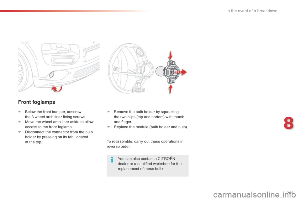
Front foglamps
You can also contact a CITROËN
dealer or a qualified workshop for the
r
eplacement of these bulbs.
F
B
elow
the
front
bumper,
unscrew
t
he 3 wheel
arch
liner
fixing
screws.
F
M
ove
the
wheel
arch
liner
aside
to
allow
a
ccess
to
the
front
foglamp.
F
D
isconnect
the
connector
from
the
bulb
h
older
by
pressing
on
its
tab,
located
at
the
top. F
R
emove the bulb holder by squeezing
the two clips (top and bottom) with thumb
a
nd
f
inger.
F
R
eplace the module (bulb holder and bulb).
To
reassemble, carry out these operations in
r
everse
o
rder.
8
In the event of a breakdown
Page 204 of 308
202
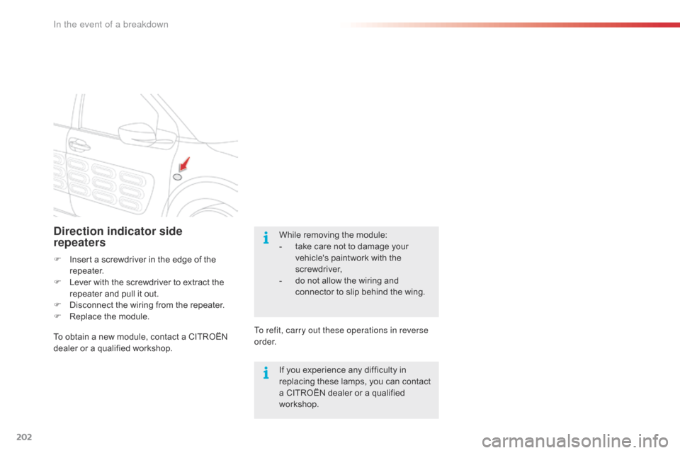
Direction indicator side
repeaters
F Insert a screwdriver in the edge of the r
epeater.
F
L
ever with the screwdriver to extract the
r
epeater and pull it out.
F
D
isconnect the wiring from the repeater.
F
R
eplace the module.
To
obtain a new module, contact a CITROËN
d
ealer or a qualified workshop. To refit, carry out these operations in reverse
o r d e r.While
removing the module:
-
t
ake care not to damage your v
ehicle's paintwork with the sc
rewdriver,
-
d
o not allow the wiring and
c
onnector to slip behind the wing.
If
you experience any difficulty in
r
eplacing these lamps, you can contact
a
CITROËN dealer or a qualified
w
orkshop.
In the event of a breakdown
Page 205 of 308
203
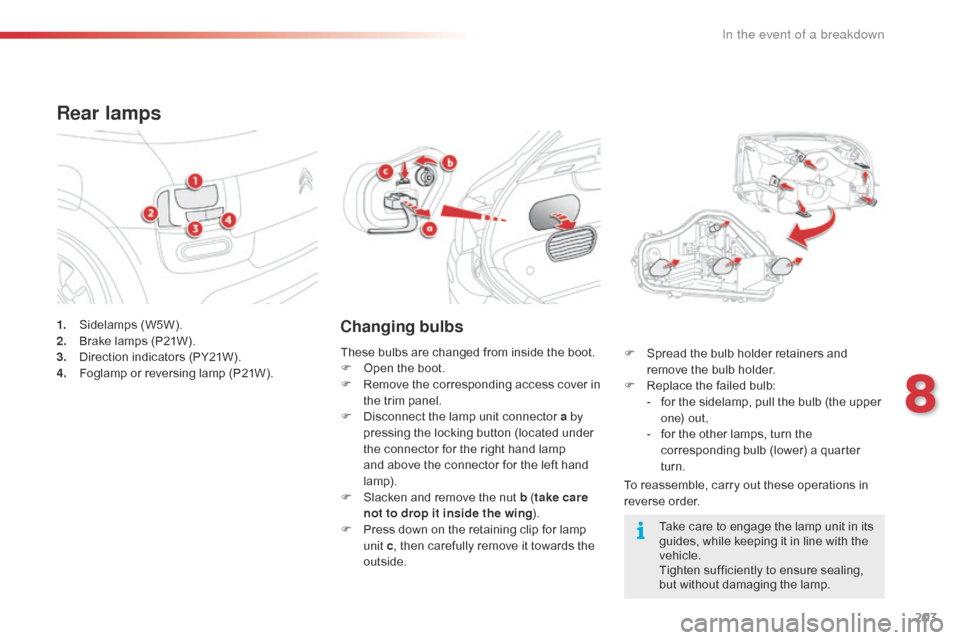
1. Sidelamps (W5W).
2. B rake lamps (P21W).
3.
D
irection indicators (PY21W).
4.
F
oglamp or reversing lamp (P21W).
Rear lamps
Changing bulbs
To reassemble, carry out these operations in reverse o rder.
F
S
pread the bulb holder retainers and
r
emove the bulb holder.
F
R
eplace the failed bulb:
-
f
or the sidelamp, pull the bulb (the upper
o
n e) o u t ,
-
f
or the other lamps, turn the
c
orresponding bulb (lower) a quarter
t
urn.
These
bulbs
are
changed
from
inside
the
boot.
F
O
pen
the
boot.
F
R
emove
the
corresponding
access
cover
in
t
he
trim
panel.
F
D
isconnect
the
lamp
unit
connector
a by
pressing
the
locking
button
(located
under
t
he
connector
for
the
right
hand
lamp
a
nd
above
the
connector
for
the
left
hand
lam
p).
F
S
lacken
and
remove
the
nut
b ( take care
not to drop it inside the wing ).
F
P
ress
down
on
the
retaining
clip
for
lamp
u
nit c,
then
carefully
remove
it
towards
the
o
utside. Take
care to engage the lamp unit in its
g
uides, while keeping it in line with the
v
ehicle.
Tighten
sufficiently to ensure sealing,
b
ut without damaging the lamp.
8
In the event of a breakdown
Page 206 of 308
204
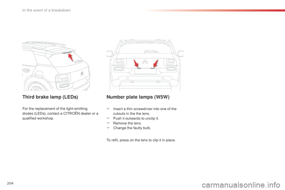
Third brake lamp (LEDs)Number plate lamps (W5W)
To refit, press on the lens to clip it in place.
F
I
nsert a thin screwdriver into one of the
c
utouts in the the lens.
F
P
ush it outwards to unclip it.
F
R
emove the lens.
F
C
hange the faulty bulb.
For
the
replacement
of
the
light-emitting
d
iodes
(LEDs),
contact
a
CITROËN
dealer
or
a
q
ualified
w
orkshop.
In the event of a breakdown
Page 207 of 308
205
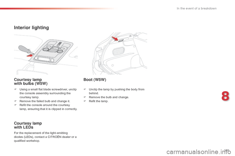
F Using a small flat blade screwdriver, unclip t
he console assembly surrounding the
c
ourtesy lamp.
F
R
emove the failed bulb and change it.
F
R
efit the console around the courtesy
l
amp, ensuring that it is clipped in correctly.
Courtesy lamp
with bulbs (W5W)
Courtesy lamp
with LEDs
For the replacement of the light-emitting diodes (LEDs), contact a CITROËN dealer or a
q
ualified
w
orkshop.
Boot (W5W)
F Unclip the lamp by pushing the body from b
ehind.
F
R
emove the bulb and change.
F
R
efit the lamp.
Interior lighting
8
In the event of a breakdown
Page 208 of 308
206
Before changing a fuse:
F t he cause of the failure must be identified
a
nd
r
ectified,
F
a
ll electrical consumers must be
s
witched off,
F
t
he vehicle must be immobilised with the
ig
nition
o
ff,
F
i
dentify the failed fuse using the tables and
l
ayout drawings in the following pages.
Changing a fuse
GoodFailed
The replacement of a fuse not shown in
t
he tables below may cause a serious
m
alfunction of your vehicle. Contact
a
CITROËN dealer or a qualified
w
orkshop. Tw e e z e r
Changing a fuse
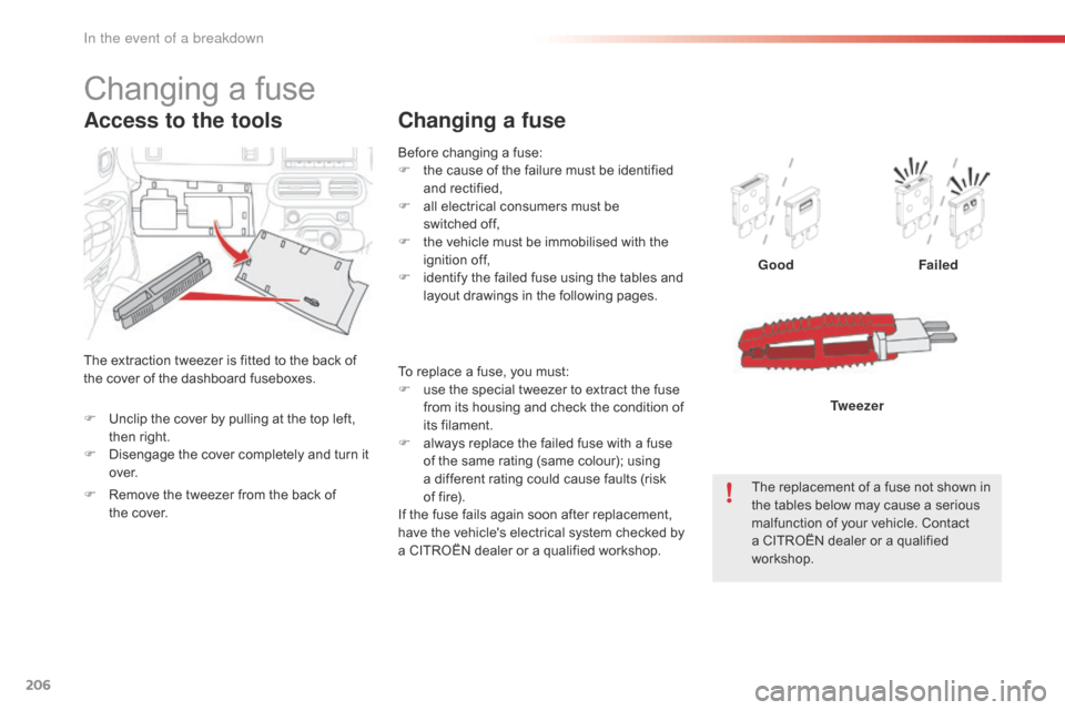
The extraction tweezer is fitted to the back of t
he cover of the dashboard fuseboxes.
Access to the tools
To replace a fuse, you must:
F u se the special tweezer to extract the fuse
f
rom its housing and check the condition of
it
s
f
ilament.
F
a
lways replace the failed fuse with a fuse
o
f the same rating (same colour); using
a
different rating could cause faults (risk
o
f fire).
If
the fuse fails again soon after replacement,
h
ave the vehicle's electrical system checked by
a
CITROËN dealer or a qualified workshop.
F
U
nclip
the
cover
by
pulling
at
the
top
left,
t
hen
right.
F
D
isengage
the
cover
completely
and
turn
it
o
ve r.
F
R
emove
the
tweezer
from
the
back
of
t
he cover.
In the event of a breakdown
Page 209 of 308
207
CITROËN will not accept responsibility
for the cost incurred in repairing your
v
ehicle or for rectifying malfunctions
r
esulting from the installation of
a
ccessories not supplied and not
r
ecommended by CITROËN and
n
ot installed in accordance with its
in
structions, in particular when the
combined
consumption of all of the
a
dditional equipment connected
e
xceeds
1
0
mil
liamperes.
Installing electrical
accessories
Your vehicle's electrical system is designed to operate with standard or
o
ptional
e
quipment.
Before
installing other electrical
e
quipment or accessories on your
v
ehicle, contact a CITROËN dealer or a
q
ualified
w
orkshop.
8
In the event of a breakdown
Page 210 of 308
208
Dashboard fuses
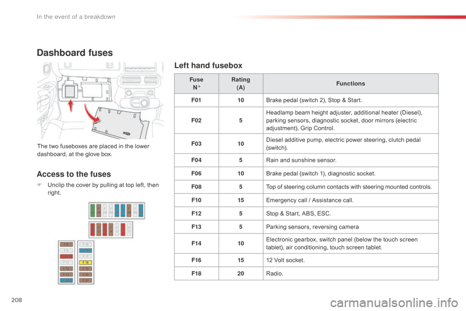
The two fuseboxes are placed in the lower dashboard, at the glove box. Fuse
N° Rating
(A) Functions
F01 10Brake pedal (switch 2), Stop & Start.
F02 5Headlamp beam height adjuster, additional heater (Diesel),
p
arking sensors, diagnostic socket, door mirrors (electric
a
djustment), Grip Control.
F03 10Diesel additive pump, electric power steering, clutch pedal (
sw i tc h).
F04 5Rain
and sunshine sensor.
F06 10Brake
pedal (switch 1), diagnostic socket.
F08 5Top
of steering column contacts with steering mounted controls.
F10 15Emergency
call / Assistance call.
F12 5Stop
& Start, ABS, ESC.
F13 5Parking
sensors, reversing camera
F14 10Electronic
gearbox, switch panel (below the touch screen
t
ablet), air conditioning, touch screen tablet.
F16 1512
Volt socket.
F18 20Radio.
Access to the fuses
F Unclip the cover by pulling at top left, then r
ight.
Left hand fusebox
In the event of a breakdown