ECU CITROEN C4 PICASSO 2022 Owner's Manual
[x] Cancel search | Manufacturer: CITROEN, Model Year: 2022, Model line: C4 PICASSO, Model: CITROEN C4 PICASSO 2022Pages: 316, PDF Size: 10.36 MB
Page 159 of 316

157
When the cruise control is working, take
care if keeping pressed one of the cruise
control programmed speed change
buttons: this can lead to a very rapid
change in the speed of your vehicle.
Do not use adaptive cruise control on
slippery sur faces or in heavy traffic.
When descending a
steep hill, the cruise
control system cannot prevent the vehicle
from exceeding the programmed speed.
On steep climbs or when towing, the
programmed speed may not be reached
or maintained.
The use of mats not approved by
CITROËN may inter fere with the operation
of the cruise control.
To avoid any risk of jamming of the pedals:
-
e
nsure that mats are secured correctly,
-
n
ever fit one mat on top of another. Operation of the radar, located in the
front bumper, may be impaired by the
accumulation of dirt (dust, mud, etc.) or in
certain weather conditions (snow, frost,
e t c .) .
The message "SYSTEM INACTIVE:
Reduced visibility". is displayed to indicate
that the function is in standby.
Clean the front bumper regularly.
If the front bumper is to be repainted or
retouched, contact a
CITROËN dealer
or a
qualified workshop. Certain types of
paint could inter fere with the operation of
the radar.
Adaptive cruise control
until vehicle is stopped/
until 19
mph (30 km/h)
Function until vehicle is stopped : with
automatic gearbox
Function until 19
mph (30 km/h): with manual
gearbox This system provides the following
functions:
-
A
utomatically maintains the
vehicle at the speed set by the
driver.
-
A
utomatic adjustment of the
distance between your vehicle
and the one in front.
Cruise control remains active after
changing gear regardless of the gearbox
type.
It manages the acceleration and deceleration
of the vehicle by automatically acting on the
engine and the braking system. With an automatic gearbox, automatic
adjustment of the distance can cause your
vehicle to come to a complete stop.
For this purpose there is a radar installed in the
front bumper.
6
Driving
Page 166 of 316

164
The system must not be activated in the
following situations:
-
W
hen the "space-saver" spare wheel is
being used (depending on version).
-
W
hen towing.
-
F
ollowing an impact on the front bumper.
Be particularly careful:
-
W
hen motorcycles are present and
when there are vehicles staggered
onto the traffic lane.
-
W
hen you enter a tunnel or cross
a
bridge. The cruise control operates by day and
night, in fog or moderate rainfall.
However, it is strongly recommended
that you always adapt your speed and
your safety distance from vehicles ahead
according to the driving conditions, the
weather and the road surface.
Use the cruise control only where
the driving conditions allow running
at a
constant speed and keeping an
adequate safety distance.
Do not activate the cruise control in urban
areas where pedestrians are likely to
cross the road, in heavy traffic, on winding
or steep roads, on slippery or flooded
roads, when there is snowfall, if the front
bumper is damaged or when the brake
lamps have failed.
In certain circumstances, it may not
be possible for the speed setting to be
maintained or even reached: loaded
vehicle, ascending a
steep hill, etc.The system is not intended for the
following situations:
-
t
he front end of the vehicle has been
modified (addition of long-range
headlamps, painting of the front
bumper),
-
d
riving on a racing track,
-
d
riving on a rolling road,
-
u
se of snow chains, non-slip covers or
studded tyres.
The use of mats not approved by
CITROËN may inter fere with the operation
of the cruise control.
To avoid any risk of jamming of the pedals:
-
e
nsure that the mat is secured
c o r r e c t l y,
-
n
ever fit one mat on top of another.
Driving
Page 195 of 316

193
Towing system with
quickly detachable towball
No tools are required to install or remove the
towball on this genuine towbar system.Trailers with LED lamps are not
compatible with the wiring harness of this
device.
Fitting Blanking plug
In the event of recovery, it is essential to remove
the blanking plug if your vehicle has one.
To do this, contact a CITROËN dealer or
a
qualified workshop.
The blanking plug is located behind the
lower air intake grille.
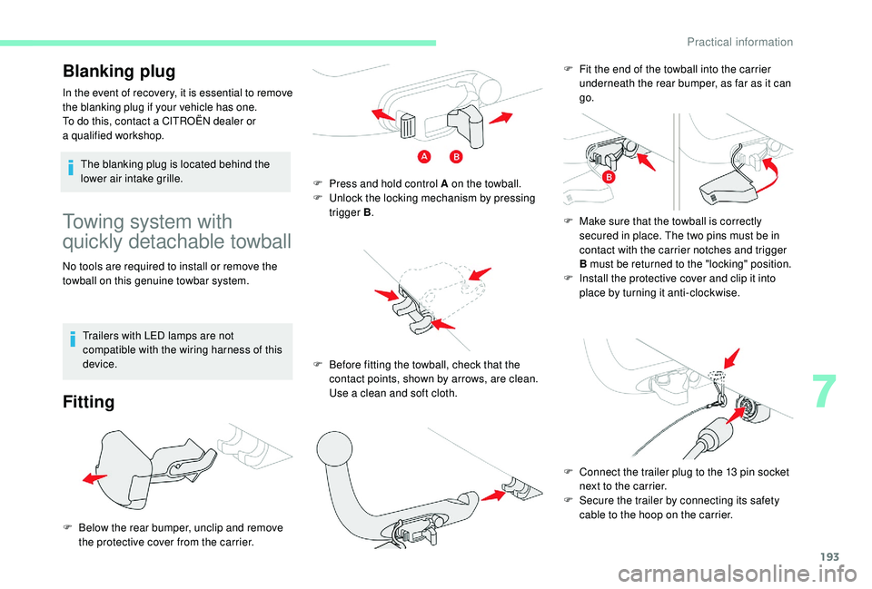
F
B
elow the rear bumper, unclip and remove
the protective cover from the carrier. F
P
ress and hold control A on the towball.
F
U
nlock the locking mechanism by pressing
trigger B .
F
B
efore fitting the towball, check that the
contact points, shown by arrows, are clean.
Use a
clean and soft cloth.F
F
it the end of the towball into the carrier
underneath the rear bumper, as far as it can
go.
F
M
ake sure that the towball is correctly
secured in place. The two pins must be in
contact with the carrier notches and trigger
B must be returned to the "locking" position.
F
I
nstall the protective cover and clip it into
place by turning it anti-clockwise.
F
C
onnect the trailer plug to the 13 pin socket
next to the carrier.
F
S
ecure the trailer by connecting its safety
cable to the hoop on the carrier.
7
Practical information
Page 198 of 316

196
Roof bars
As a safety measure and to avoid
d amaging the roof, it is essential to use
the transverse bars approved for your
vehicle.
Obser ve the fitting instructions and the
conditions of use in the user guide supplied
with the bars.
Version without longitudinal
bars Version with longitudinal
bars
Recommendations
F Distribute the load evenly, avoiding
overloading on one side.
F
A
rrange the heaviest part of the load as
close as possible to the roof.
F
S
ecure the load firmly and fit a warning flag
if it overhangs the vehicle.
F
D
rive gently: the vehicle will be more
susceptible to the effects of side winds (the
stability of the vehicle may be affected).
F
R
emove the roof bars once they are no
longer needed.
After refitting a front wiper
bla de
F Switch on the ignition.
F
O perate the wiper control stalk again to
park the wiper blades.
The replacement of wiper arms should be
carried out only by a
CITROËN dealer or
a
qualified workshop. When fitting roof bars, use only the four fixing
points located on the roof frame. These points
are masked by the vehicle doors when closed.
The roof bar fixings include a
stud which should
be fitted to the opening in each fixing point. You must fit the transverse bars to the
longitudinal bars at the fixing points indicated
by engraved markings on the longitudinal bars.
Practical information
Page 211 of 316

209
F Park the vehicle without obstructing any traffic and apply the parking brake.
F
F
ollow the safety instructions (hazard
warning lamps, warning triangle, wearing
high visibility vest, etc.) according to the
legislation in force in the country where you
are driving.
F
S
witch off the ignition.
F
U
ncoil the pipe stowed under the
compressor. Avoid removing any foreign bodies which
have penetrated into the tyre.F
R
emove the valve cap from the tyre to be
repaired, and place it in a
clean area.
F
C
heck that the compressor switch is at the
" O " position.
F U ncoil fully the electric cable, stowed under
the compressor.
Only the 12
V socket located at the front of
the vehicle can be used.
F
A
ffix the speed limit sticker.
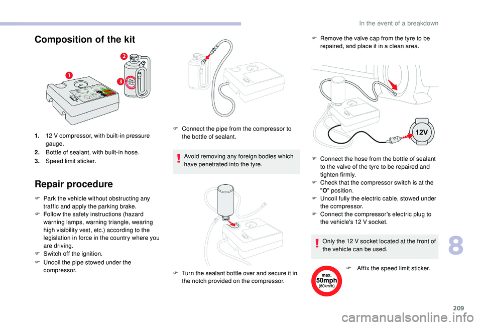
1.
12 V compressor, with built-in pressure
gauge.
2. Bottle of sealant, with built-in hose.
3. Speed limit sticker.
Repair procedure Composition of the kit
F Connect the pipe from the compressor to
the bottle of sealant.
F
T
urn the sealant bottle over and secure it in
the notch provided on the compressor. F
C
onnect the hose from the bottle of sealant
to the valve of the tyre to be repaired and
tighten firmly.
F
C
onnect the compressor's electric plug to
the vehicle's 12
V socket.
8
In the event of a breakdown
Page 212 of 316

210
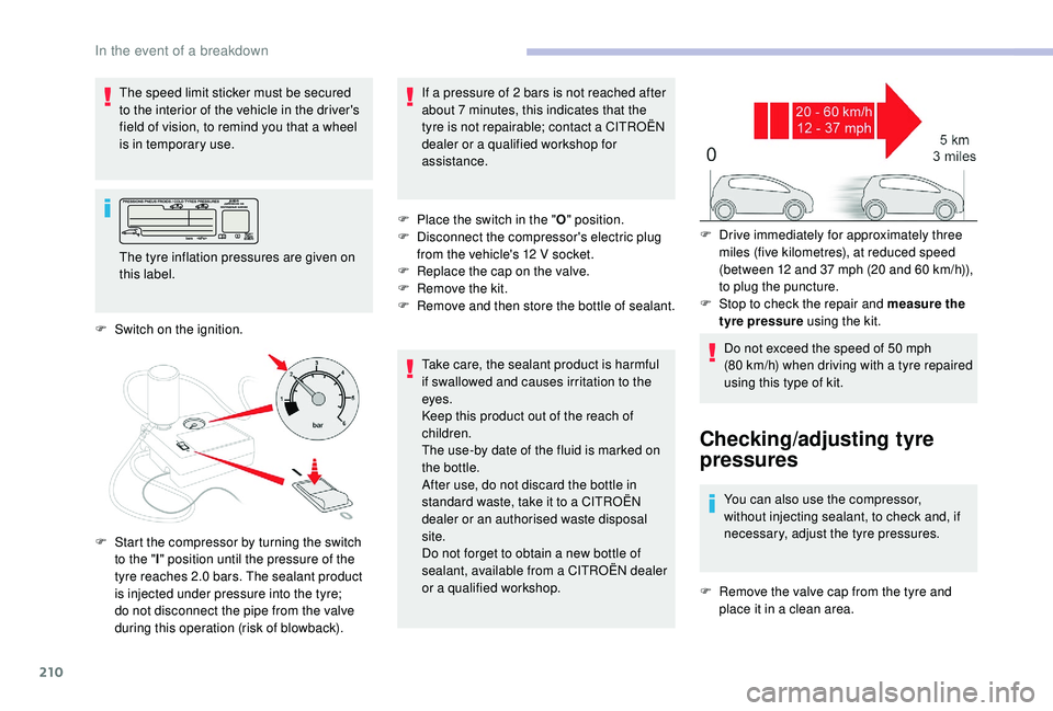
The speed limit sticker must be secured
to the interior of the vehicle in the driver's
field of vision, to remind you that a wheel
is in temporary use.
The tyre inflation pressures are given on
this label.
F
S
witch on the ignition.
F
S
tart the compressor by turning the switch
to the " l" position until the pressure of the
tyre reaches 2.0
bars. The sealant product
is injected under pressure into the tyre;
do not disconnect the pipe from the valve
during this operation (risk of blowback). If a
pressure of 2 bars is not reached after
about 7 minutes, this indicates that the
tyre is not repairable; contact a
CITROËN
dealer or a
qualified workshop for
assistance.
F
P
lace the switch in the "O" position.
F
D
isconnect the compressor's electric plug
from the vehicle's 12
V socket.
F
R
eplace the cap on the valve.
F
R
emove the kit.
F
R
emove and then store the bottle of sealant.
Take care, the sealant product is harmful
if swallowed and causes irritation to the
eyes.
Keep this product out of the reach of
children.
The use-by date of the fluid is marked on
the bottle.
After use, do not discard the bottle in
standard waste, take it to a
CITROËN
dealer or an authorised waste disposal
site.
Do not forget to obtain a
new bottle of
sealant, available from a
CITROËN dealer
or a
qualified workshop.F
D
rive immediately for approximately three
miles (five kilometres), at reduced speed
(between 12
and 37 mph (20 and 60 km/h)),
to plug the puncture.
F
S
top to check the repair and measure the
tyre pressure using the kit.
Do not exceed the speed of 50
mph
(80
km/h) when driving with a tyre repaired
using this type of kit.
Checking/adjusting tyre
pressures
You can also use the compressor,
without injecting sealant, to check and, if
necessary, adjust the tyre pressures.
F
R
emove the valve cap from the tyre and
place it in a
clean area.
In the event of a breakdown
Page 214 of 316

212
List of tools
(Depending on equipment.)4.
Wheel bolt cover removal tool.
Removes the wheel bolt covers on alloy
wheels.
5. Socket for the security bolts (located in
the glove box).
For adapting the wheelbrace to the special
"security" bolts.
6. Towing eye and tool to open the front
protective cover.
1. Wheelbrace.
For removing the wheel trim and the wheel
fastening bolts.
2. Chock to immobilise the vehicle (except
versions with manual gearbox).
3. Jack with integrated handle.
Used to raise the vehicle. For more information on To w i n g
, refer to the
corresponding section.
All of these tools are specific to your
vehicle and may vary according to the
level of equipment.
Do not use them for any other purposes.
The jack must only be used to change
a wheel with a damaged or punctured tyre.
Do not use any jack other than the one
supplied with this vehicle.
If the vehicle does not have its original jack,
contact a
CITROËN dealer or a qualified
workshop to obtain the correct jack for it.
The jack meets European standards,
as defined in the Machinery Directive
2006/42/EC.
The jack does not require any
maintenance.
Access to the spare wheel
The spare wheel is located in the boot, under
t h e f l o o r.
Taking out the wheel
F Loosen the central nut.
F R emove the fastening device (nut and bolt).
F
R
aise the spare wheel towards you from the
r e a r.
F
T
ake the wheel out of the boot.
In the event of a breakdown
Page 215 of 316

213
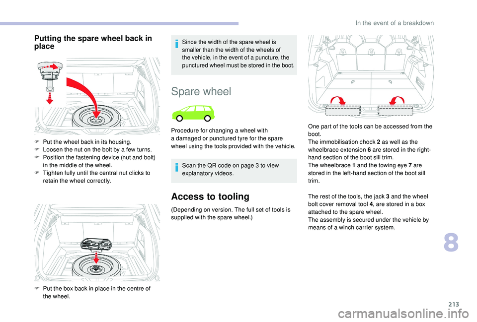
Putting the spare wheel back in
placeSince the width of the spare wheel is
smaller than the width of the wheels of
the vehicle, in the event of a puncture, the
punctured wheel must be stored in the boot.
F Put the wheel back in its housing.
F L oosen the nut on the bolt by a few turns.
F
P
osition the fastening device (nut and bolt)
in the middle of the wheel.
F
T
ighten fully until the central nut clicks to
retain the wheel correctly.
F
P
ut the box back in place in the centre of
the wheel.
Spare wheel
Scan the QR code on page 3 to view
e xplanatory videos.
Access to tooling
(Depending on version. The full set of tools is
supplied with the spare wheel.) The rest of the tools, the jack 3
and the wheel
bolt cover removal tool 4 , are stored in a box
attached to the spare wheel.
The assembly is secured under the vehicle by
means of a
winch carrier system.
Procedure for changing a
wheel with
a damaged or punctured tyre for the spare
wheel using the tools provided with the vehicle. One part of the tools can be accessed from the
boot.
The immobilisation chock 2 as well as the
wheelbrace extension 6 are stored in the right-
hand section of the boot sill trim.
The wheelbrace 1 and the towing eye 7 are
stored in the left-hand section of the boot sill
trim.
8
In the event of a breakdown
Page 216 of 316

214
List of tools
(Depending on version. The full set of tools is
supplied with the spare wheel.)
1.Wheelbrace.
For removing the wheel trim and removing
the wheel bolts.
2. Chock to immobilise the vehicle (except
for versions with manual gearbox).
3. Jack with integrated handle.
Used to raise the vehicle. 4.
Wheel bolt cover removal tool.
Removes the wheel bolt covers on alloy
wheels.
5. Socket for wheel security bolts (stored in
the glove box).
For adapting the wheelbrace to the special
"security" bolts.
6. Wheelbrace extension.
For slackening/tightening the spare wheel
winch cable carrier nut.
7. Towing eye and tool to open the front
protective cover.
For more information on To w i n g , refer to the
corresponding section.
All of these tools are specific to your
vehicle and may vary according to the
level of equipment.
Do not use them for any other purposes.
The jack must only be used to change
a wheel with a damaged or punctured tyre.
Do not use any jack other than the one
supplied with this vehicle.
If the vehicle does not have its original jack,
contact a
CITROËN dealer or a qualified
workshop to obtain the correct jack for it.
The jack meets European standards,
as defined in the Machinery Directive
2006/42/EC.
The jack does not require any
maintenance.
Wheel with wheel trim
When removing the wheel , first remove the
trim using the wheelbrace 1 by pulling at the
valve aperture.
When refitting the wheel , refit the trim
starting by placing its notch facing the valve
and press around its edge with the palm of your
hand.
Access to the spare wheel
(Depending on version.)
Only a "space-saver" type spare wheel
may be fixed underneath the vehicle.
The spare wheel is supported by a
winch
carrier system underneath the vehicle.
In the event of a breakdown
Page 219 of 316

217
Removing a wheel
* position P for the automatic gearbox
Parking the vehicle
Stop the vehicle where it does not block
traffic: the ground must be level, stable
and non-slippery.
Apply the parking brake, unless it is
programmed in automatic mode; switch
off the ignition and put the vehicle into first
gear* so as to block the wheels.
Check that the braking warning lamp and
the P warning lamp in the parking brake
control lever come on.
For more safety, position the
chock
2 against the wheel opposite the one you
are replacing.
Make absolutely certain that all the
occupants have left the vehicle and are
waiting in a safe area.
Never go underneath a vehicle raised
using a jack; use an axle stand.
Do not use:
-
t
he jack for any other purpose than
lifting the vehicle,
-
a j
ack other than the one supplied by
the manufacturer.
List of operationsF Place the foot of the jack 3 on the ground
and ensure that it is directly below the front
A or rear B jacking point provided on the
underbody, whichever is closest to the
wheel to be changed.
Ensure that the jack is stable. If the
ground is slippery or loose, the jack may
slip or collapse – Risk of injury!
Ensure that the jack is positioned only at
one of the jacking points A or B under the
vehicle, making sure that the vehicle's
contact sur face is centred on the head of
the jack. Otherwise, the vehicle could be
damaged and/or the jack could collapse –
Risk of injury!
F
R
emove the bolt cover(s) using the tool 4
(according to equipment).
F
F
it security socket 5
on wheelbrace 1
to
slacken the security bolt (according to
equipment).
F
S
lacken the other bolts (no more than
a
1/4
turn) using the wheelbrace 1
o n l y. F
E
xtend the jack 3 until its head comes into
contact with jacking point A or B used,
with contact sur face A or B on the vehicle
correctly engaged with the central part of
the head of the jack.
8
In the event of a breakdown