tow Citroen C4 RHD 2015 2.G Owner's Guide
[x] Cancel search | Manufacturer: CITROEN, Model Year: 2015, Model line: C4 RHD, Model: Citroen C4 RHD 2015 2.GPages: 328, PDF Size: 12.72 MB
Page 189 of 328
1111
187
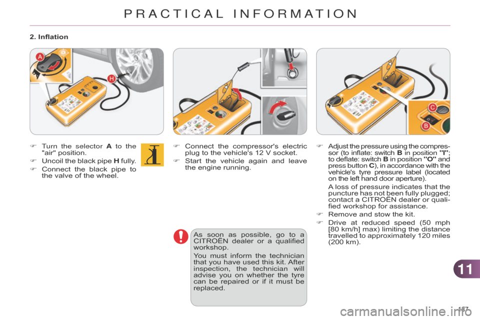
F Connect the compressor's electric plug
to the vehicle's 12 V socket.
F
Start
the
vehicle
again
and
leave
the
engine running.
As
soon
as
possible,
go
to
a
CITROËN
dealer
or
a
qualified
workshop.
Y
ou
must
inform
the
technician
that
you
have
used
this
kit.
After
inspection, the technician will
advise
you
on
whether
the
tyre
can
be
repaired
or
if
it
must
be
replaced.
F
T
urn the selector A to the
"air"
position.
F
Uncoil
the
black
pipe
H
fully
.
F
Connect
the
black
pipe
to
the
valve
of
the
wheel.
2. Inflation
F Adjust the pressure using the compres -
sor (to inflate: switch B in position
"I";
to
deflate:
switch
B
in
position
"O"
and press button
C),
in
accordance
with
the vehicle's
tyre
pressure
label
(located on
the left hand door aperture).
A loss
of
pressure
indicates
that
the
puncture
has
not
been
fully
plugged;
contact
a
CITROËN
dealer
or
quali
-
fied
workshop for assistance.
F
Remove
and stow the kit.
F
Drive
at
reduced
speed
(50
mph
[80
km/h]
max)
limiting
the
distance
travelled
to
approximately
120
miles
(200
km).
PRACTICAL INFORMATION
Page 190 of 328
1111
188
Removing the cartridge
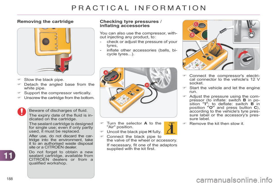
F Stow the black pipe.
F
Detach
the
angled
base
from
the
white
pipe.
F
Support
the compressor vertically.
F
Unscrew the cartridge from the bottom.
F Connect the compressor's electri -
cal connector to the vehicle's 12 V
socket.
F
Start
the
vehicle
and
let
the
engine
run.
F
Adjust
the
pressure
using
the
com
-
pressor
(to
inflate:
switch
B
in po-
sition "I";
to
deflate:
switch
B
in
position "O"
and
press
button
C
),
according
to
the
vehicle's
tyre
pres
-
sure
label
or
the
accessory's
pres
-
sure
label.
F
Remove
the kit then stow it.
Beware
of
discharges
of
fluid.
The
expiry
date
of
the
fluid
is
in
-
dicated
on
the
cartridge.
The
sealant
cartridge
is
designed
for
single
use;
even
if
only
partly
used,
it
must
be
replaced.
After
use,
do
not
discard
the
car
-
tridge
into
the
environment,
take it
to
an
authorised
waste
disposal site
or
a
CITROËN
dealer.
Do
not
forget
to
obtain
a
new
sealant
cartridge,
available
from
CITROËN
dealers
or
from
a
qualified
workshop.
Checking tyre pressures /
inflating accessories
You can also use the compressor , with -
out injecting any product, to:
-
check
or
adjust
the
pressure
of
your
tyres,
-
inflate
other
accessories
(balls,
bi
-
cycle
tyres...).
F
T
urn the selector A to the
"Air"
position.
F
Uncoil
the
black
pipe
H
fully
.
F
Connect
the
black
pipe
to
the
valve
of
the
wheel
or
accessory
.
If
necessary
,
fit
one
of
the
adaptors
supplied
with the kit first.
PRACTICAL INFORMATION
Page 191 of 328
1111
189
CHANGING A WHEEL
Procedure for changing a faulty wheel for
the spare wheel using the tools pro -
vided
with the vehicle.
Access to the tools
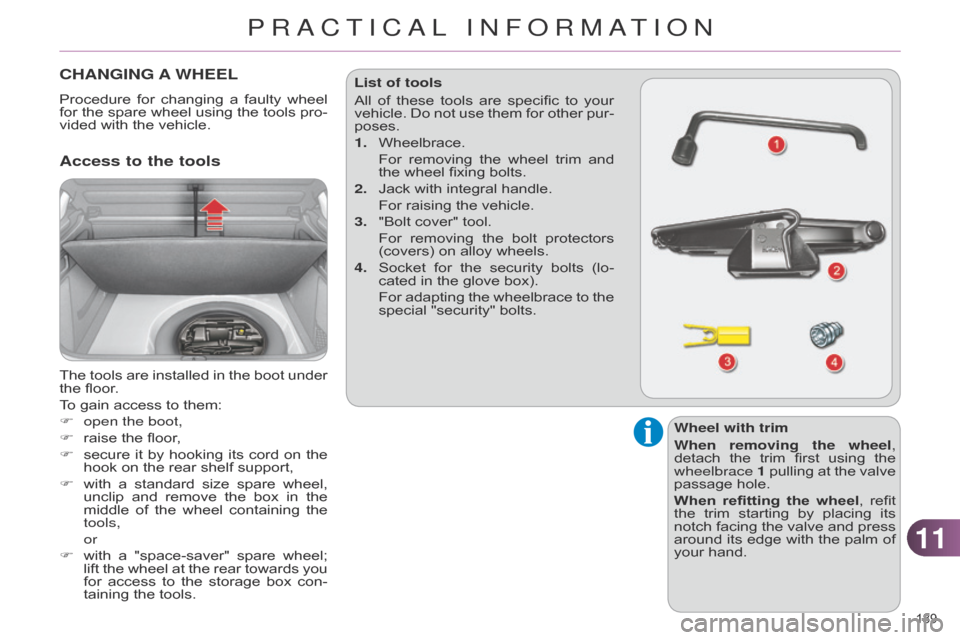
The tools are installed in the boot under the
floor.
To
gain access to them:
F
open the boot,
F
raise
the floor,
F
secure
it
by
hooking
its
cord
on
the
hook
on the rear shelf support,
F
with
a
standard
size
spare
wheel,
unclip
and
remove
the
box
in
the
middle
of
the
wheel
containing
the
tools,
or
F
with
a
"space-saver"
spare
wheel;
lift
the
wheel
at
the
rear
towards
you
for
access
to
the
storage
box
con
-
taining
the tools. List of tools
All
of
these
tools
are
specific
to
your
vehicle.
Do
not
use
them
for
other
pur
-
poses.
1.
Wheelbrace.
For
removing
the
wheel
trim
and
the
wheel fixing bolts.
2.
Jack
with integral handle.
For
raising the vehicle.
3.
"Bolt
cover" tool.
For
removing
the
bolt
protectors
(covers)
on alloy wheels.
4.
Socket
for
the
security
bolts
(lo
-
cated in the glove box).
For
adapting
the
wheelbrace
to
the
special
"security" bolts.
Wheel with trim
When removing the wheel,
detach
the
trim
first
using
the
wheelbrace 1
pullin
g
at
the
valve
passage
hole.
When refitting the wheel,
refit
the
trim
starting
by
placing
its
notch
facing
the
valve
and
press
around
its
edge
with
the
palm
of
your
hand.
PRACTICAL INFORMATION
Page 192 of 328
1111
190
Access to the spare wheel
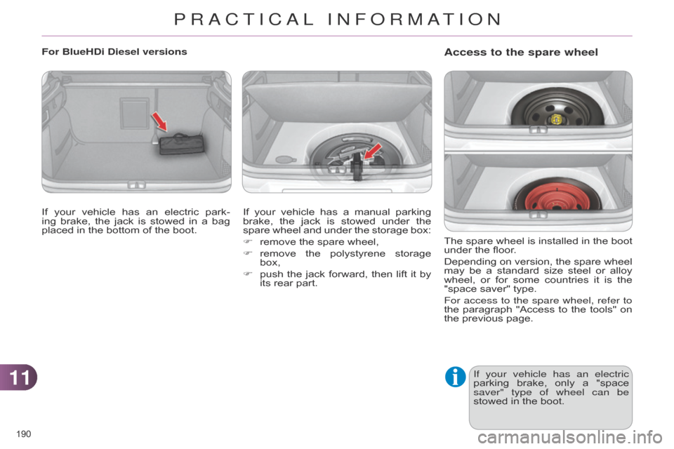
The spare wheel is installed in the boot under
the floor.
Depending
on
version,
the
spare
wheel
may
be
a
standard
size
steel
or
alloy
wheel,
or
for
some
countries
it
is
the
"space
saver" type.
For access to the spare wheel, refer to
the
paragraph
"Access
to
the
tools"
on
the
previous page.
If your vehicle has an electric
parking
brake,
only
a
"space
saver" type of wheel can be
stowed
in the boot.
For BlueHDi Diesel versions
If
your
vehicle
has
an
electric
park
-
ing
brake,
the
jack
is
stowed
in
a
bag
placed
in
the
bottom
of
the
boot. If
your
vehicle
has
a
manual
parking
brake,
the
jack
is
stowed
under
the
spare
wheel
and
under
the
storage
box:
F
remove
the
spare
wheel,
F
remove
the
polystyrene
storage
box,
F
push
the
jack
forward,
then
lift
it
by
its
rear
part.
PRACTICAL INFORMATION
Page 193 of 328

1111
191
Putting the standard wheel back in
placeTyre under-inflation detection
The
spare
wheel
is
not
fitted
with
a
sensor
.
The
punctured
wheel
must
be
repaired
by
a
CITROËN
dealer
or aqualified workshop.
Taking out the standard wheel
F
Put
the wheel back in its housing.
F
Unscrew
the
yellow
central
bolt
by
a
few turns then put it in place in the
centre
of the wheel.
F
T
ighten
fully
until
the
central
bolt
clicks
to retain the wheel correctly.
F
Unscrew
the
yellow
central
bolt.
F
Raise
the
spare
wheel
towards
you
from
the
rear.
F
T
ake
the
wheel
out
of
the
boot. F
Put
the
box
back
in
place
in
the
cen
-
tre
of the wheel and clip it.
PRACTICAL INFORMATION
Page 198 of 328
1111
196
CHANGING A BULB
The headlamps are fitted with polycarbonate
glass with a pro -
tective
coating:
F
do not clean them using a
dry or abrasive cloth,
nor
with a detergent or solvent
product,
F
use
a
sponge
and
soapy
wa
-
ter
or a pH neutral product,
F
when
using
a
high
pressure
washer
on
persistent
marks,
do
not
keep
the
lance
direct
-
ed
towards
the
lamps
or
their
edges
for
too
long,
so
as
not
to
damage
their
protective
coating
and seals.
Changing
a
bulb
should
only
be
done
after
the
headlamp
has
been
switched
of
f
for
several
minutes
(risk of serious burns).
F
Do
not
touch
the
bulb
directly
with
your
fingers,
use
a
lint-
free
cloth.
It
is
imperative
to
use
only
anti-
ultraviolet
(UV)
type
bulbs
to
avoid
damaging the headlamp.
Always
replace
a
failed
bulb
with
a
new
bulb
with
the
same
type
and
specification. Risk of electrocution
Xenon
bulbs
(D1S-35W)
must
be replaced
by
a
CITROËN
dealer or
a qualified workshop.
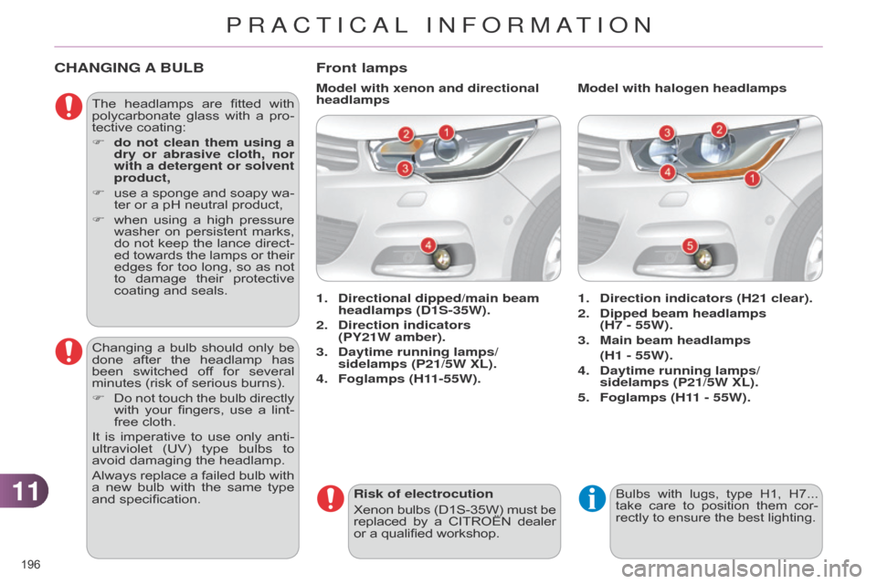
Front lamps
1. Direction indicators (H21 clear).
2.
Dipped beam headlamps
(H7 - 55W).
3.
Main beam headlamps
(H1 - 55W).
4.
Daytime running lamps/
sidelamps (P21/5W XL).
5.
Foglamps (H1
1 - 55W).
1.
Directional dipped/main beam
headlamps (D1S-35W).
2.
Direction indicators
(PY21W
amber).
3.
Daytime running lamps/
sidelamps (P21/5W XL).
4.
Foglamps (H1
1-55W). Model with halogen headlamps
Model with xenon and directional
headlamps
Bulbs with lugs, type H1, H7... take
care to position them cor -
rectly
to ensure the best lighting.
PRACTICAL INFORMATION
Page 201 of 328

1111
199
F Introduce a flat screwdriver in the hole
in the finisher.
F
Pull
and
lever
to
unclip
the
bumper
finisher
(the
parking
sensor
stays
with
the finisher).
F
Remove
the
two
module
fixing
screws and
remove it from its housing.
F
Disconnect
the bulb holder connector.
F
T
urn
the
bulb
holder
a
quarter
of
a
turn
and extract it.
F
Pull
the bulb and change it.
To
refit,
carry
out
these
operations
in
reverse
order.
To
replace
these
bulbs
you
may
also contact
a
CITROËN
dealer
or
a
qualified workshop. Changing foglamp bulbs
Changing the side spotlamps
For
the
replacement
of
this
type
of
LED
lamp,
contact
a
CITROËN
dealer
or
a
qualified
workshop.
Changing integrated direction
indicator side repeaters
F
Insert
a
screwdriver
towards
the
centre of the repeater between the
repeater
and
the
base
of
the
mirror.
F
T
ilt
the
screwdriver
to
extract
the
re
-
peater
and
remove
it.
F
Disconnect
the
repeater
connector.
To
reassemble,
carry
out
these
operations in
reverse
order.
Contact a CITROËN dealer or a qualified workshop
to obtain replacement repeaters.
PRACTICAL INFORMATION
Page 202 of 328
1111
200
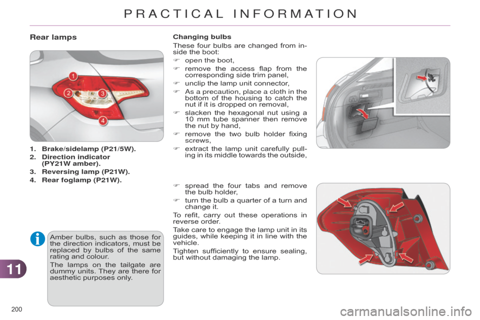
Rear lamps
1. Brake/sidelamp (P21/5W).
2.
Direction
indicator
(PY21W amber).
3.
Reversing lamp (P21W).
4.
Rear
foglamp (P21W).
Amber
bulbs,
such
as
those
for
the
direction
indicators,
must
be
replaced
by
bulbs
of
the
same
rating
and colour.
The
lamps
on
the
tailgate
are
dummy
units.
They
are
there
for
aesthetic
purposes only.Changing bulbs
These
four
bulbs
are
changed
from
in
-
side the boot:
F
open the boot,
F
remove
the
access
flap
from
the
corresponding
side trim panel,
F
unclip
the lamp unit connector,
F a s a precaution, place a cloth in the
bottom
of
the
housing
to
catch
the
nut
if it is dropped on removal,
F
slacken
the
hexagonal
nut
using
a
10
mm
tube
spanner
then
remove
the
nut by hand,
F
remove
the
two
bulb
holder
fixing
screws,
F
extract the lamp unit carefully pull -
ing in its middle towards the outside,
F
spread
the
four
tabs
and
remove
the
bulb holder,
F
turn
the
bulb
a
quarter
of
a
turn
and
change
it.
To
refit,
carry
out
these
operations
in
reverse
order.
Take
care
to
engage
the
lamp
unit
in
its
guides,
while
keeping
it
in
line
with
the
vehicle.
T
ighten
sufficiently
to
ensure
sealing,
but
without damaging the lamp.
PRACTICAL INFORMATION
Page 212 of 328
1111
210
VERY COLD CLIMATE SCREEN *
* According to country.
Fitting
F Offer up the very cold climate screen to the front of the lower sec
-
tion
of the front bumper.
F
Press
around
its
edge
to
engage
its
fixing
clips one by one.
Removal
F Use a screwdriver as a lever to re -
lease each fixing clip in turn.
Do
not
forget
to
remove
the
very
cold
climate screen when:
-
the
ambient
temperature
ex
-
ceeds
10 °C,
-
towing,
-
driving at speeds above 75 mph
(120
km/h).
Removable
protective
screen
which
prevents
the
accumulation
of
snow
at
the
radiator
cooling
fan.
FITTING ROOF BARS
For safety
reasons and to avoid dam -
aging the roof, it is essential to use the
transverse
bars
approved
for
your
ve
-
hicle.
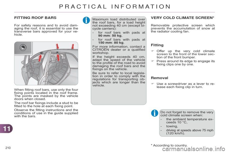
When
fitting
roof
bars,
use
only
the
four
fixing
points
located
in
the
roof
frame.
The
points
are
masked
by
the
vehicle
doors
when closed.
The
roof
bar
fixings
include
a
stud
to
be
fitted
to the hole at each fixing point.
Observe
the
fitting
instructions
and
the
conditions
of
use
in
the
guide
supplied
with
the bars. Maximum
load
distributed
over
the
roof bars, for a load height not
exceeding 40 cm (except bi -
cycle
carriers):
-
for
roof
bars
with
pads
at
90
mm: 50 kg,
-
for
roof
bars
with
pads
at
150
mm: 80 kg.
For
more
information,
contact
a
CITROËN
dealer
or
a
qualified
workshop.
If
the
height
exceeds
40
cm,
adapt
the
speed
of
the
vehicle
to
the
profile
of
the
road
to
avoid
damaging
the
roof
bars
and
the
fixings
on the vehicle.
Be
sure
to
refer
to
local
legisla
-
tion
in
order
to
comply
with
the
regulations
for
transporting
ob
-
jects
which
are
longer
than
the
vehicle.
PRACTICAL INFORMATION
Page 213 of 328
1111
211
TOWING THE VEHICLE
Procedure for having your vehicle towed
or for towing another vehicle us -
ing
a removable towing eye.
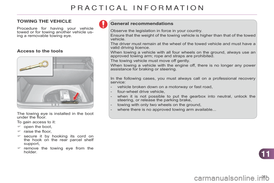
The
towing
eye
is
installed
in
the
boot
under
the floor.
To
gain access to it:
F
open the boot,
F
raise
the floor,
F
secure
it
by
hooking
its
cord
on
the
hook
on
the
rear
parcel
shelf
support,
F
remove
the
towing
eye
from
the
holder
.
Access to the tools General recommendations
Observe the legislation in force in your country.
Ensure
that
the
weight
of
the
towing
vehicle
is
higher
than
that
of
the
towed
vehicle.
The
driver
must
remain
at
the
wheel
of
the
towed
vehicle
and
must
have
a
valid
driving licence.
When
towing
a
vehicle
with
all
four
wheels
on
the
ground,
always
use
an
approved
towing arm; rope and straps are prohibited.
The
towing vehicle must move off gently.
When
towing
a
vehicle
with
the
engine
of
f,
there
is
no
longer
any
power
assistance
for braking or steering.
In
the
following
cases,
you
must
always
call
on
a
professional
recovery
service:
-
vehicle
broken down on a motorway or fast road,
-
four-wheel
drive vehicle,
-
when
it
is
not
possible
to
put
the
gearbox
into
neutral,
unlock
the
steering,
or release the parking brake,
-
towing
with only two wheels on the ground,
-
where
there is no approved towing arm available...
PRACTICAL INFORMATION