clock CITROEN C5 AIRCROSS 2020 Handbook (in English)
[x] Cancel search | Manufacturer: CITROEN, Model Year: 2020, Model line: C5 AIRCROSS, Model: CITROEN C5 AIRCROSS 2020Pages: 292, PDF Size: 8.59 MB
Page 141 of 292

139
The units for the speed limits (mph or
km/h) depend on the country you are
driving in.
It should be taken into account so that you
obser ve the speed limit.
For the system to operate correctly when
you change country, the units for speed in
the instrument panel must be those for the
country you are driving in.
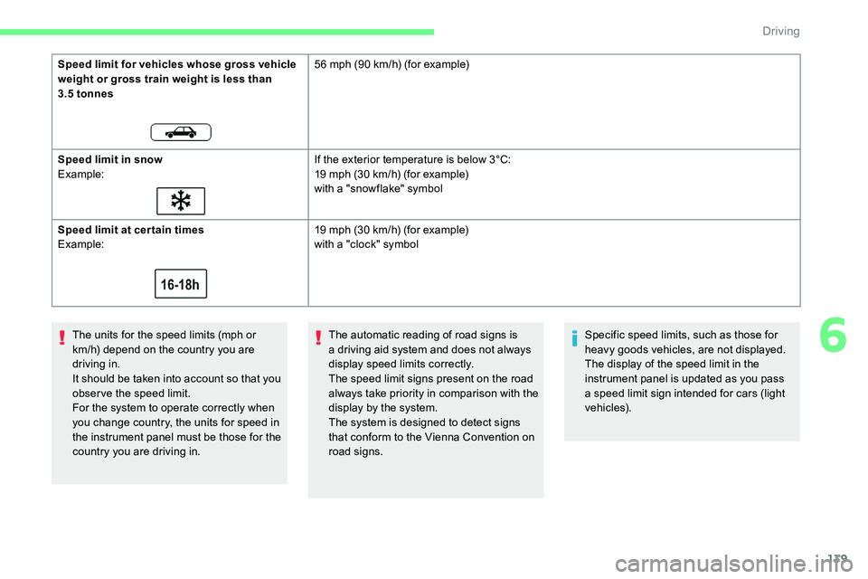
Speed limit for vehicles whose gross vehicle
weight or gross train weight is less than
3.5
tonnes
56 mph (90 km/h) (for example)
Speed limit in snow
Example: If the exterior temperature is below 3°C:
19 mph (30 km/h) (for example)
with a "snowflake" symbol
Speed limit at cer tain times
Example: 19 mph (30 km/h) (for example)
with a "clock" symbol
The automatic reading of road signs is
a driving aid system and does not always
display speed limits correctly.
The speed limit signs present on the road
always take priority in comparison with the
display by the system.
The system is designed to detect signs
that conform to the Vienna Convention on
road signs. Specific speed limits, such as those for
heavy goods vehicles, are not displayed.
The display of the speed limit in the
instrument panel is updated as you pass
a
speed limit sign intended for cars (light
vehicles).
6
Driving
Page 186 of 292

184
F The wheel 6 turns a quarter of a turn anti-
clockwise; take care to keep your hands
clear!
F
C
heck that the mechanism has correctly
locked into place (position A ).
F
C
lose the lock 7 using the key.
F
A
lways remove the key. The key cannot be
removed when the lock is open.
F
C
lip the cap onto the lock.
During use
Never release the locking system with
a
trailer or load carrier on the towball.
Never exceed the maximum authorised
weight for the vehicle – the Gross Train
Weight or GTW.
It is essential that the maximum
authorised load be complied with on the
towing device: if it is exceeded, this device
may detach from the vehicle, which is
a
serious accident risk.
Check that the trailer lamps work
c o r r e c t l y.
Before setting off, check the adjustment of
the headlamp beam height.
For more information on Headlamp
adjustment , refer to the corresponding
section.
After use
When travelling without a
trailer or load
carrier, the towball must be removed and
the protective plug inserted in the carrier
for good visibility of the number plate and
its lighting.Fitting the towball
F Insert the end of the towball 5 into the
carrier 1 and push it upwards; the locking
will take place automatically.
F
B
elow the rear bumper, remove the
protective plug 2 from the carrier 1
.
Practical information
Page 187 of 292

185
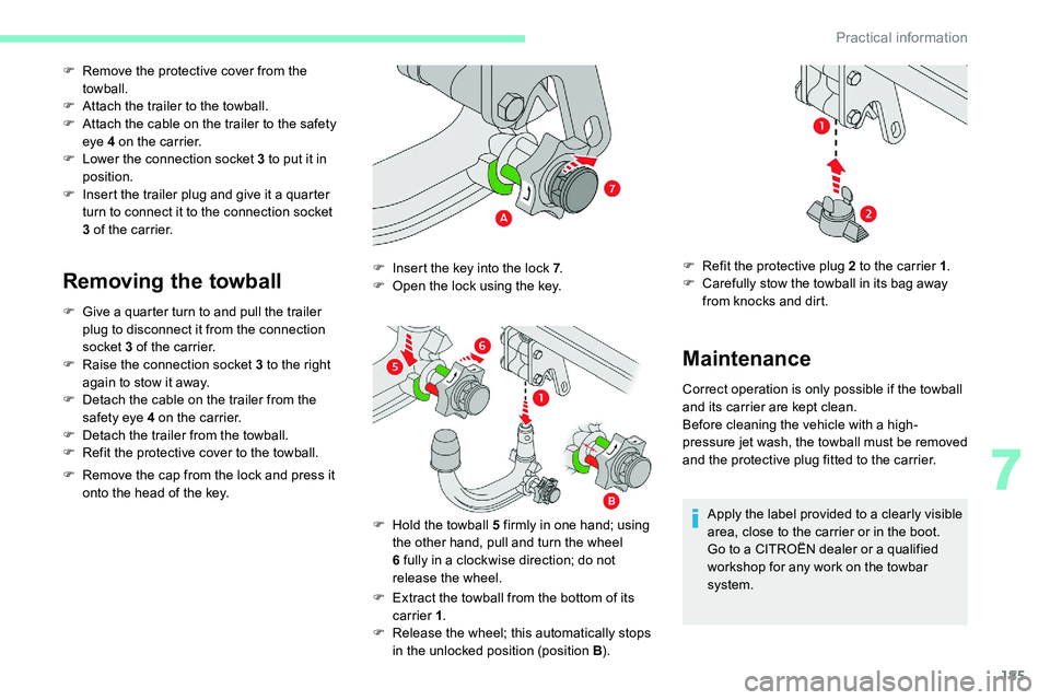
F Remove the protective cover from the towball.
F
A
ttach the trailer to the towball.
F
A
ttach the cable on the trailer to the safety
eye 4
on the carrier.
F
L
ower the connection socket 3 to put it in
position.
F
I
nsert the trailer plug and give it a quarter
turn to connect it to the connection socket
3
of the carrier.
Removing the towball
F Give a quarter turn to and pull the trailer
plug to disconnect it from the connection
socket 3
of the carrier.
F
R
aise the connection socket 3 to the right
again to stow it away.
F
D
etach the cable on the trailer from the
safety eye 4
on the carrier.
F
D
etach the trailer from the towball.
F
R
efit the protective cover to the towball.
F
R
emove the cap from the lock and press it
onto the head of the key.
F
E
xtract the towball from the bottom of its
carrier 1 .
F
R
elease the wheel; this automatically stops
in the unlocked position (position B ).
F
I
nsert the key into the lock 7
.
F
O
pen the lock using the key.
F
H
old the towball 5 firmly in one hand; using
the other hand, pull and turn the wheel
6
fully in a clockwise direction; do not
release the wheel.
Maintenance
Correct operation is only possible if the towball
and its carrier are kept clean.
Before cleaning the vehicle with a
high-
pressure jet wash, the towball must be removed
and the protective plug fitted to the carrier.
Apply the label provided to a
clearly visible
area, close to the carrier or in the boot.
Go to a
CITROËN dealer or a qualified
workshop for any work on the towbar
system.
F
R
efit the protective plug 2 to the carrier 1
.
F
C
arefully stow the towball in its bag away
from knocks and dirt.
7
Practical information
Page 198 of 292

196
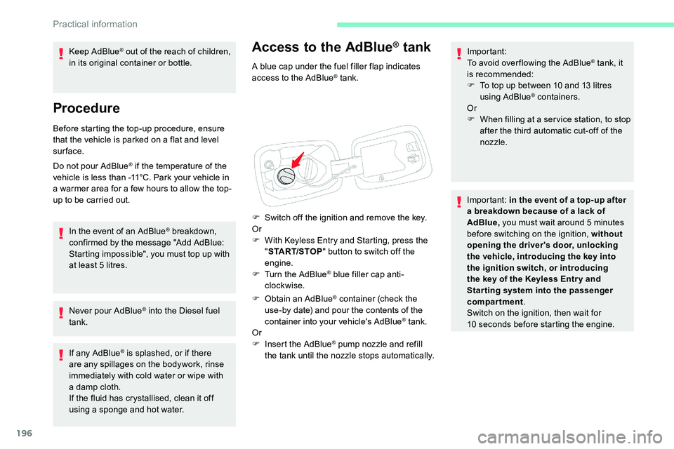
Access to the AdBlue® tank
A blue cap under the fuel filler flap indicates
access to the AdBlue® tank.
F
S
witch off the ignition and remove the key.
Or
F
W
ith Keyless Entry and Starting, press the
" START/STOP " button to switch off the
engine.
F
T
urn the AdBlue
® blue filler cap anti-
clockwise.
F
O
btain an AdBlue
® container (check the
use-by date) and pour the contents of the
container into your vehicle's AdBlue
® tank.
Or
F
I
nsert the AdBlue
® pump nozzle and refill
the tank until the nozzle stops automatically. Important:
To avoid over flowing the AdBlue
® tank, it
is recommended:
F
T
o top up between 10
and 13
litres
using AdBlue
® containers.
Or
F
W
hen filling at a ser vice station, to stop
after the third automatic cut-off of the
nozzle.
Important: in the event of a
top-up after
a
breakdown because of a lack of
AdBlue, you must wait around 5
minutes
before switching on the ignition, without
opening the driver's door, unlocking
the vehicle, introducing the key into
the ignition switch, or introducing
the key of the Keyless Entr y and
Star ting system into the passenger
compartment .
Switch on the ignition, then wait for
10
seconds before starting the engine.
Keep AdBlue
® out of the reach of children,
in its original container or bottle.
Procedure
Before starting the top-up procedure, ensure
that the vehicle is parked on a flat and level
sur face.
Do not pour AdBlue
® if the temperature of the
vehicle is less than -11°C. Park your vehicle in
a
warmer area for a
few hours to allow the top-
up to be carried out.
In the event of an AdBlue
® breakdown,
confirmed by the message "Add AdBlue:
Starting impossible", you must top up with
at least 5
litres.
Never pour AdBlue
® into the Diesel fuel
tank.
If any AdBlue
® is splashed, or if there
are any spillages on the bodywork, rinse
immediately with cold water or wipe with
a
damp cloth.
If the fluid has crystallised, clean it off
using a
sponge and hot water.
Practical information
Page 199 of 292

197
Warning triangle
As a safety precaution, before leaving your
v ehicle to set up and install the triangle, switch
on the hazard warning lamps and put on your
high visibility vest.
Storage compartment
There is a compartment in the interior trim of
t he tailgate to store a triangle.
F
O
pen the tailgate.
F
R
elease the cover by turning the screw
a
quarter turn anti-clockwise.
Assembling and placing the
triangle
For versions supplied with a triangle as original
e quipment, refer to the illustration above.
For other versions, refer to the assembly
instructions provided with the triangle.
F
P
ut the triangle in place behind the vehicle,
as required by local legislation.
Running out of fuel (Diesel)
On vehicles fitted with Diesel engines, the fuel
system must be primed if you run out of fuel.
If the engine does not start first time, do not
keep trying, but start the procedure again from
the beginning. For more information on Misfuel
prevention (Diesel)
, refer to the
corresponding section.
BlueHDi 130 engines
F Fill the fuel tank with at least 5 litres of
Diesel.
F
S
witch on the ignition (without starting the
engine).
F
W
ait around 1 minute and switch off the
ignition.
F
O
perate the starter to start the engine.
If the engine does not start, repeat the
procedure.
BlueHDi 180 engines
F Fill the fuel tank with at least 5 litres of
Diesel.
F
S
witch on the ignition (without starting the
engine).
F
W
ait around 6 seconds and switch off the
ignition.
F
R
epeat the last two operations 10 times.
F
O
perate the starter to start the engine.
8
In the event of a breakdown
Page 210 of 292

208
Model C
1.Daytime running lamps/sidelamps (LED).
2. Direction indicators (W Y21W).
3. Dipped beam headlamps (H7-55W).
4. Main beam headlamps (HB3-65W).
5. Front foglamps (P21W).
Opening the bonnet /Access to bulbs
With the engine warm, proceed with
caution – Risk of burns!
Take care with objects or clothing that
could be caught in the blades of the
engine fan – Risk of strangulation!
Direction indicators (halogen
headlamps)
Rapid flashing of a direction indicator
l amp (left or right) indicates that one of
the bulbs on the corresponding side has
failed.
Amber coloured bulbs, such as the
direction indicators, must be replaced
by bulbs with identical colour and
specifications.
Main beam headlamps (halogen
headlamps)
F Turn the bulb holder a quarter turn anti-
clockwise.
F
P
ull the bulb and bulb holder assembly
rearwards.
F
R
eplace the bulb.
To refit, carry out these operations in reverse
o r d e r. F
R
emove the protective cover.
F
D
isconnect the bulb connector.
F
T
urn the bulb holder anti-clockwise.
F
R
emove the bulb and replace it.
To refit, carry out these operations in reverse
order. When refitting, close the protective cover
very carefully to guarantee the sealing of the
lamp.
In the event of a breakdown
Page 211 of 292

209
Dipped beam headlamps (halogen
headlamps)
F Remove the protective cover.
F D isconnect the bulb connector.
F
T
urn the lamp a quarter turn anti-clockwise
and replace it.
To refit, carry out these operations in reverse
order. When refitting, close the protective cover
very carefully to guarantee the sealing of the
lamp.
Daytime running lamps/sidelamps
(LEDs)
For the replacement of this type of diode bulb,
contact a CITROËN dealer or a qualified
workshop.
Changing foglamp bulbsTo replace this type of bulb, you can also
contact a CITROËN dealer or a qualified
workshop.
Direction indicator side repeaters
(LED)
For the replacement of this type of diode bulb,
contact a CITROËN dealer or a qualified
workshop.
Door mirror spotlamps (LED)
For the replacement of this type of diode bulb,
contact a CITROËN dealer or a qualified
workshop.
F
I
ntroduce a
flat screwdriver in the hole in
the trim.
F
P
ull and lever to unclip the foglamp trim.
F
W
ith a
Torx screwdriver, remove the two
module fixing screws.
F
R
emove the module from its housing.
F
D
isconnect the bulb holder connector.
F
T
urn the bulb holder a
quarter turn and pull
it out.
F
C
hange the assembly.
To refit, carry out these operations in reverse
o r d e r.
8
In the event of a breakdown