engine Citroen CX 1981 1.G Workshop Manual
[x] Cancel search | Manufacturer: CITROEN, Model Year: 1981, Model line: CX, Model: Citroen CX 1981 1.GPages: 394
Page 231 of 394
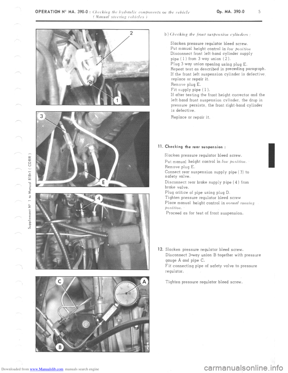
Downloaded from www.Manualslib.com manuals search engine Slacken pressure regulator bleed screw.
Put manual height control in /VII. position
Disconnect front left-hand cylinder supply
pipe ( 1 ) from 3~woy union (2 ).
Plug 3-way union opening using plug E.
Repeat test as described in preceding parograpb.
If the front left suspension cylinder is defective
replace 01 repair it.
Remove plug E.
Fit supply pipe ( 1 ).
If after testing the front height corrector and the
left-hand front suspension cvlinder, the drop in
pressure persists, the front right-hand cylinder
is defective.
Replace or repair it. Il.
Checking the rear suspension :
Slacken pressure regulator bleed screw.
Put manual height control in IOU pnsi!ios,
Remove plug E.
Connect rear suspension supply pipe (?) to
safety valve.
Disconnect rear brake supply pipe (4) from
brake valve.
Plug oriilce of pipe using plug D.
Tighten pressure regulator bleed screw
Place manual height control in aorwnl rrruniug
posilio,,.
Proceed as for test of front suspension.
12. Slacken pressure regulator bleed screw.
Disconnect 3-way union B together with pressure
gauge A and pipe C.
Fit connecting pipe of safety valve to pressure
regulator.
Tighten pressure regulator bleed screw.
Page 232 of 394
Downloaded from www.Manualslib.com manuals search engine FRONT AXLE
OPERATION No MA. 410-00 : Charnctvristics arid S(ICJCI’O~ /‘rattrres o,i the front as/e unit Op. MA. 410-00 1
t
SWIVEL
L. 41-l
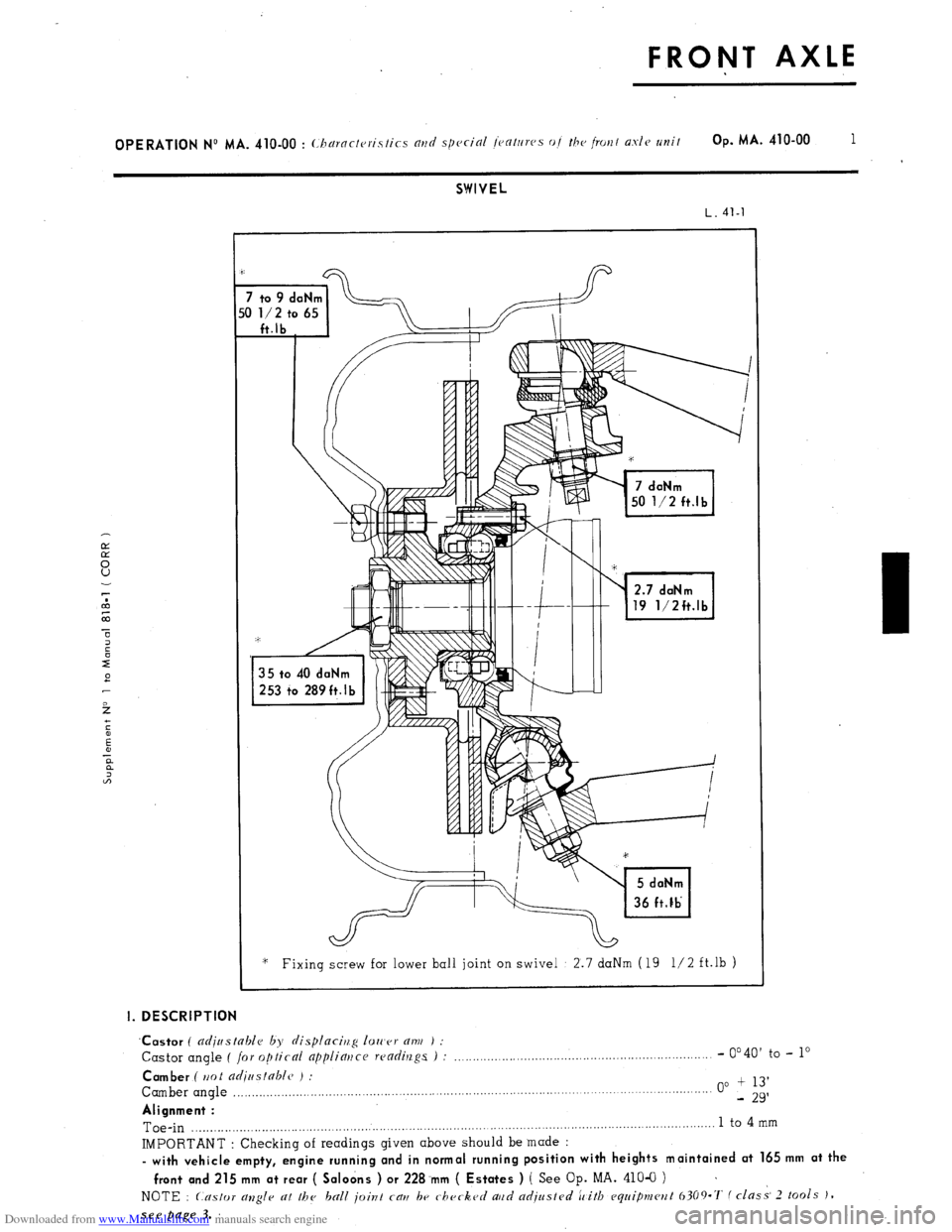
2.7 daNm
19 1/2ft.lb
‘* Fixing screw for lower ball joint on swivel 2.7 daNm (19 l/2 ft.lb )
I. DESCRIPTION
‘Castor
( adjustable by displacirlg 1011’er am ) :
Castor angle ( for optical appliatjce readings ) : _.,,....._..._,......,,,,,,.......,.,........,,,.,......,,............ - 0’40’
to - lo
Camber ( ttot adiastable ) :
Camber angle ,,.,,,.,,,..._,,,__.....,...,,.........,,.,.......................................................................... . . . . . 00 + 13’
- 29’
Alignment :
Toe-in ,.........._.__...,.,..,.,,.,,,,,.........,,,,.,......................,....................................................................... 1 to 4
mm
IMPORTANT : Checking of readings given above should be made :
- with vehicle empty, engine running and in normal running position with heights maintained at 165 mm at the
front and 215 mm at rear ( Saloons ) or 228.mm ( Estates ) ( See
Op. MA. 410-O ) ~
NOTE : Castor allgle at the ball joint cau be checked aud adjusted ic’itb equipmcwt 6309.7‘ f class- 2 tools J,
see page 3.
Page 233 of 394
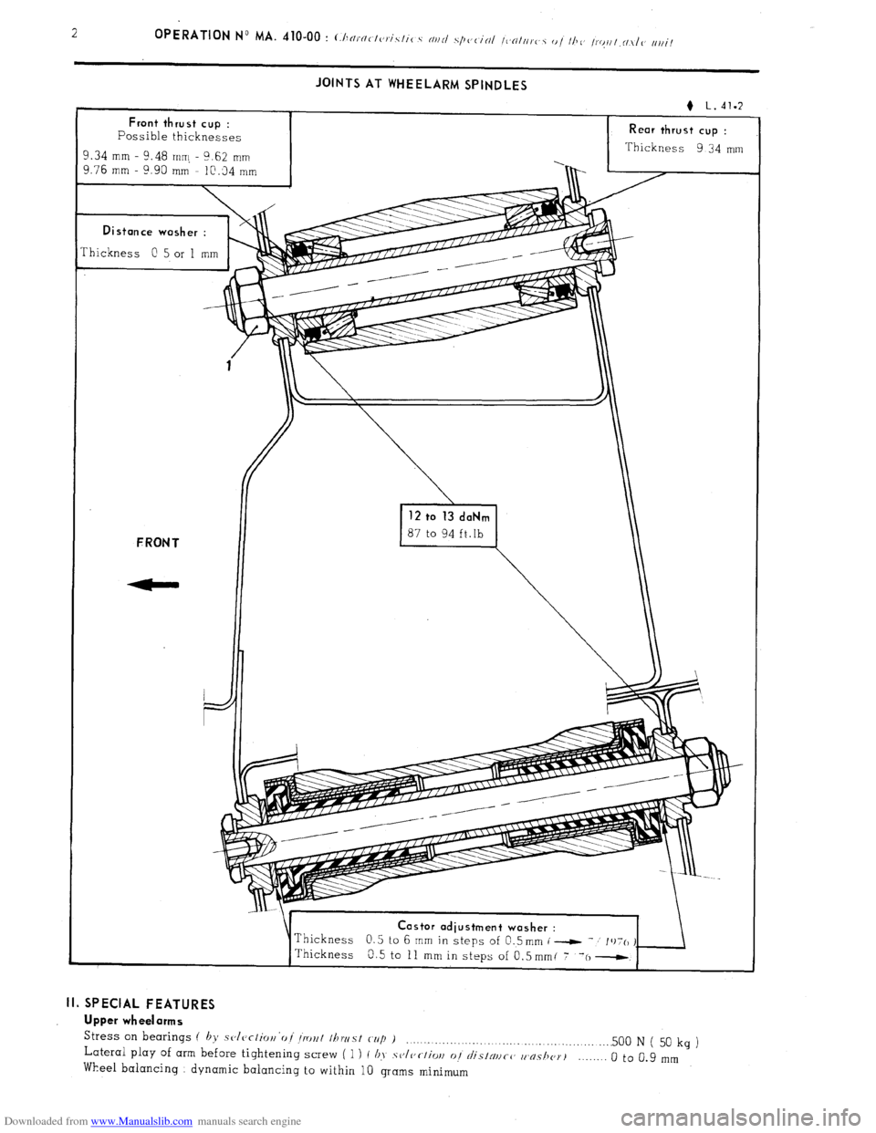
Downloaded from www.Manualslib.com manuals search engine JOINTS AT WHEELARM SPINDLES
Rear thrust cup :
Thickness 9 34 mm
Thickness
0 5 or 1 mm astor adiustment washer :
II. SPECIAL FEATURES
Upper wheelarms
Stress
on bearings ( by sclcrlior~‘oi Iro~l Ihwst cup ) _....._._........._... . . . . .._.............. .._..... 500 N ( 50 Lateral play of arm before tightening screw ( 1 ) I b>, .sv/c,c~/iw 01 ~~I/‘SINIICC, w~s/I~~T~ kg
)
Wheel balancing dynamic balancing to within 10 grams minimum _._..._. 0 to 0.9 mm
Page 234 of 394
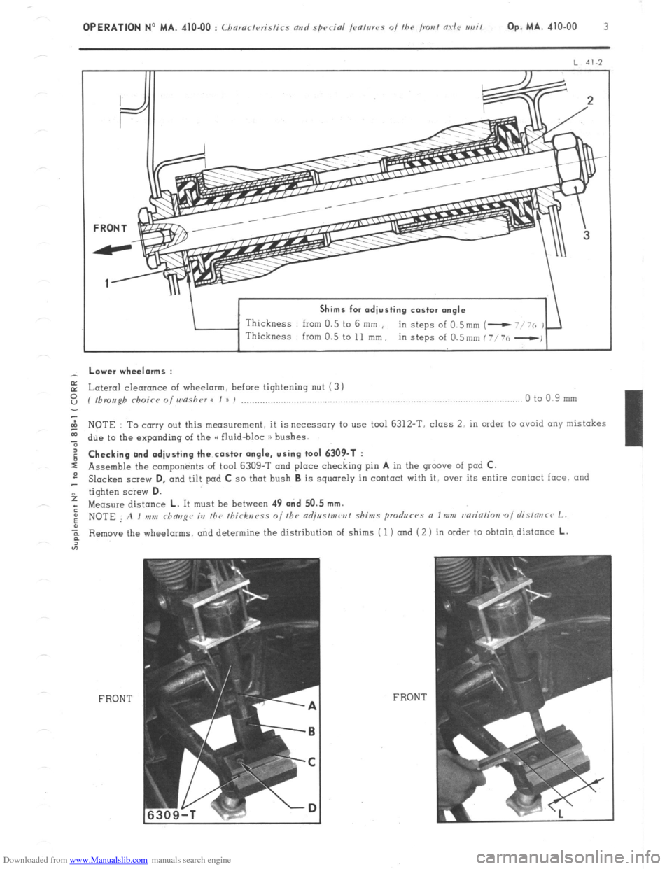
Downloaded from www.Manualslib.com manuals search engine Shims for adjusting castor angle
Thickness from 0.5 to 6 mm ,
in steps of 0.5mm (- - Lower wheelorms :
E Lateral cleoronce of wheelarm. before tightening nut (3 1
z ( fbmugh rhoicr o/ wnshr~r I I u I ,..................,.,............................,..,..,.,........................,....,...... 0 to 0.9 mm
2 NOTE To carry out this measurement, it is necessary to use tool 6312-T. class 2. in order to ovoid any mistakes
t due to the expanding of the G fluid-bloc n bushes. g Checking and adjusting the castor angle, using tool 6309-T :
s Assemble the components of tool 6309-T and place checking pin A in the groove of pod C.
2 Slacken screw D,
and tilt pad C so that bush B is squarely in contact with it, over its entire contact face. and
f tighten screw D.
; Measure distance L. It must be between 49 and 50.5 mm.
: NOTE A I mm rhaug~~ ia the Ihirknrss o//he adjr~s/mw/ shims produc-~s a Imm r~ariatim oi rlislmc~ L.
Remove the wheelarms, and determine the distribution of shims ( 1) and ( 2 ) in order to obtain distance L.
FRONT FRON T
Page 235 of 394

Downloaded from www.Manualslib.com manuals search engine 4 OPERATION No MA. 410-00 : (haractvristirs avd special jmtms oi the irout aslc urrit REPAIRS :
- Old type (( fluid-bloc )) bushes ( length : 79.5 mm ) must not be fitted with the later wheelarms.. and vice-versa.
- It is possible, on any vehicle, to fit one, or both sides with the later wheelarms, providing the appropriate shims
are used.
Page 236 of 394
Downloaded from www.Manualslib.com manuals search engine OPERATION No MA. 410-O : ( /,c
1
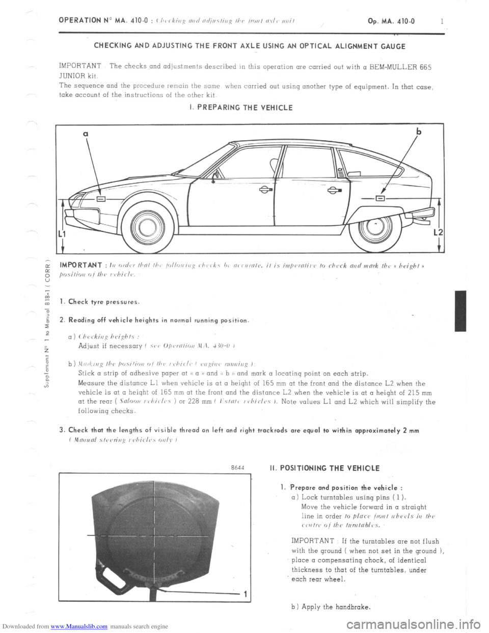
CHECKING AND ADJUSTING THE FRONT AXLE USING AN OPTICAL ALIGNMENT GAUGE
IMPORTANT The checks and adjustments described in this operation are carried out with a BEM-MULLER 665
JUNIOR kit
The sequence and
the procedure remain the same when carried out using another type of equipment. In that case,
take account of the instructions of the other kit I. PREPARING THE VEHICLE
cl
b
-.
I t 1. Check tyre pressures.
2. Rending off vehicle heights in normal running position
c,)
b ) .\I ri,f,,,g /he ,w.s;‘;o,,
Measure the distance Ll when vehicle is at II height of 165 mm at the front and the distance L2 when the
vehicle is at CL height of 165 mm at the front and the distance L2 when the vehicle is at a height of 215 mm
at the rear ( .Snloo,, I vhi~/r,s 1 or 228 mm I I:.s/o/c / chirlr,. 1. Note values Ll and L2 which will simplify the
following checks. 3. Check that the lengths of visible thread on left and right trackrods are equal to within approximately 2 mm
r .Mm,,tnl 51<,<,r;r,,q I <,hirl?s WI). )
r
Rh‘td Ii. POSITIONING THE VEHIOLE
7
-1 1. Prepare and position the vehicle :
a) Lock turntables using pins ( 1 ).
Move the vehicle forward in a straight
line in order 10 plnce ironl r,hccls iv
Ihe
rwrtw o/’ fhC /,,n,tab/~s.
IMPORTANT If the turntables ore not flush
with the ground ( when not set in the ground ),
place a compensating chock, of identical
thickness to that of the turntables, under
each rear wheel.
b 1 Apply the hondbrake.
Page 237 of 394
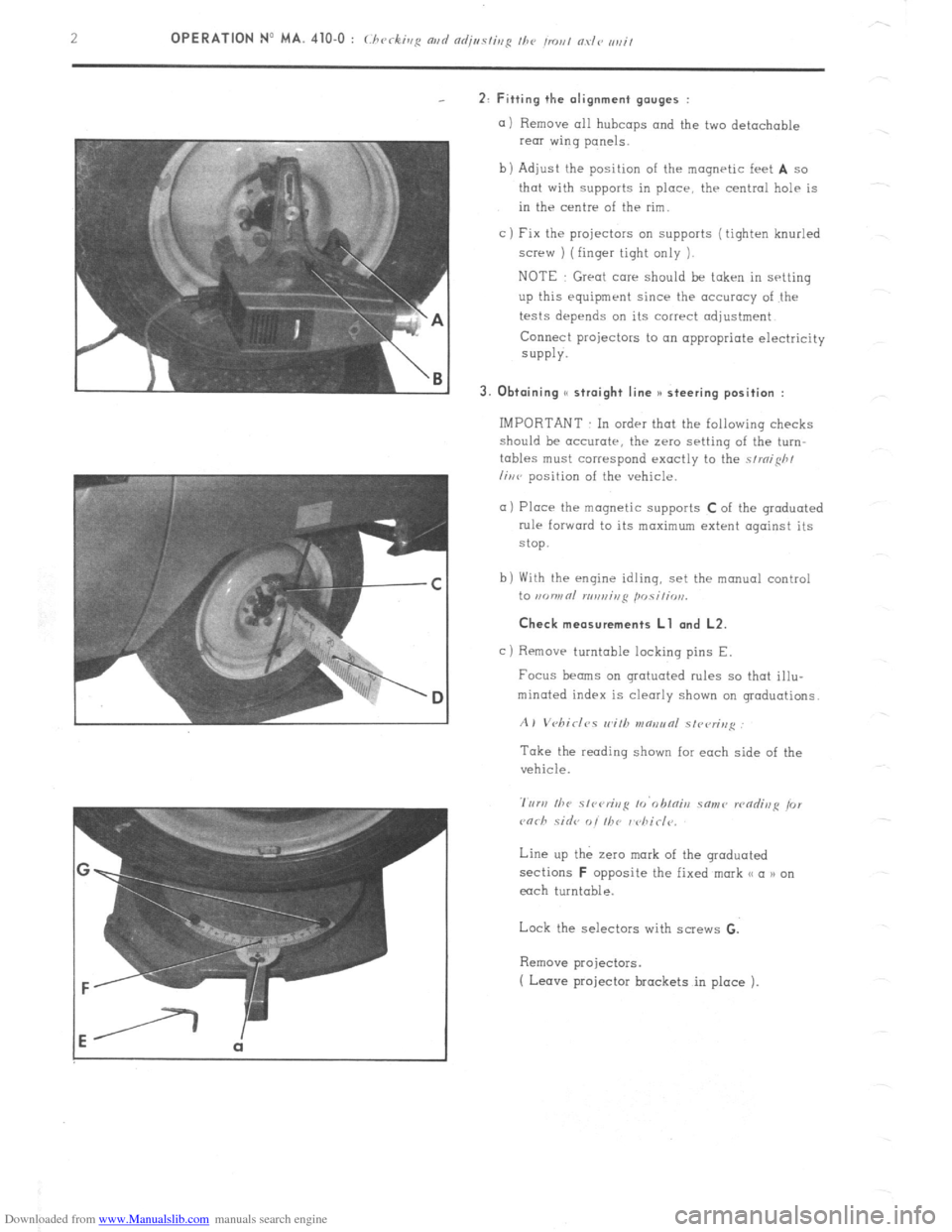
Downloaded from www.Manualslib.com manuals search engine 2: Fitting the alignment gauges :
a) Remove all hubcaps and the two detachable
rear wing panels.
b) Adjust the position of the magnetic feet
A so
that with supports in place, thr central help is
in the centre of the rim.
c ) Fix the projectors on supports ( tighten knurled
screw ) (finger tight only 1.
NOTE Great care should be taken in setting
up this equipment since the accuracy of the
tests depends on its correct adjustment
Connect projectors to on appropriate electricity
SUPPlY.
3. Obtaining S( straight line )I steering position :
IMPORTANT In order that the following checks
should be accurate, the zero setting of the turn-
tables must correspond exactly to the strnifih/
liwv position of the vehicle.
a) Place the magnetic supports C of the graduated
rule forward to its maximum extent against its
stop.
b) With the engine idling, set the manual control
to ,KJWRl n,n,,ir,ji posili, ,,,.
Check measurements Ll and L2.
c)
Removr turntable locking pins E.
Focus beams on grotuoted rules so that illu-
minated index is clearly shown on graduations.
A) Vebirlc,s wilh v~aeunl slvvrin,~
Take the reading shown for each side of the
vehicle.
Line up the zero mark of the graduated
sections
F opposite the fixed mark << a n on
each turntable.
Lock the selectors with screws G.
Remove projectors.
( Leave projector brackets in place ).
Page 238 of 394
Downloaded from www.Manualslib.com manuals search engine Op. MA. 410.0 3
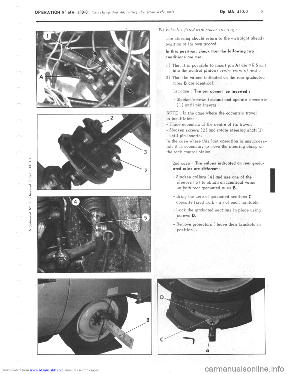
The steering should return to the (( straight ahead n
position of its own accord. In this position, check that the following !wo
conditions me met.
1 ) That it is possible to insert pin A (dia =6.5mm)
into the control pinion (rwrrr poiat oi rack J
2) That the values indicated on the rear graduated
rules B ore identical.
1st case : The pin cannot be inserted :
- Slackenvscrews ( -c) and operate eccentric
i 1 i until pin inserts.
NOTE In the case where the eccentric travel
is insufficient :
- Place eccentric ot the centre of its travel.
- Slacken screws (2 ) and rotate steering shaft(!)
until pin inserts.
In the case where this last operation is unsuccess-
ful, it is necessary to move the steering clamp on
the rock control pinion.
2nd case : The values indicated on rear gradu-
ated rules ore different :
- Slacken collars ( 4) and use one of the
sleeves ( 5 1 to obtain an identical value
on Path rear graduated rules 6.
- Bring the Z~IO of graduated sections C
opposite fixed mark <( a )I of each turntable.
- Lock the graduated sections in place using screws D.
Page 239 of 394
Downloaded from www.Manualslib.com manuals search engine III. CHECKING THE CAMBER ANGLE
NOTE : The camber angle is not adjustable.
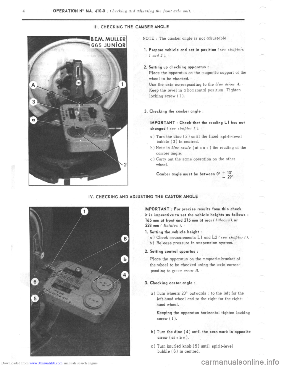
1. Prepare vehicle and set in position f src chapfrrs
I and 2 ).
2. Setting up checking apparatus :
Place the apparatus on the magnetic support of the
wheel to be checked.
Use the axis corresponding to the blue mmu A..
Keep the level in a horizontal position. Tighten
locking screw ( 1).
3. Checking the comber angle :
IMPORTANT : Check that the reading Ll has not
changed ( SC<’ rhnprcr I ).
a) Turn the disc (2 ) until the fixed spirit-level
bubble (3 1 is centred.
b) Note in blur scnle (at o a n ) the reading of the
comber rmqle.
c ) Carry out the same operation on the other
wheel.
Comber angle must be between 0’ + 13’ - 29’
IV. CHECKING AND ADJUSTING THE,CASTOR ANGLE
IMPORTANT : For precise results from this check
it is imperative to set the vehicle heights as follows :
165 mm a+ front and 215 mm at rear f Salooss) or
228 mm ( Esfafes ).
1. Setting the vehicle height :
a) Check measurements Ll and L2 f see chapter I ).
b ) Release pressure in suspension system.
2. Setting control opportus :
3. Checking castor angle :
Place the apparatus on the magnetic bracket of
the wheel to be checked using the axis corres-
ponding to grren (ITTOII’ H.
a) Turn wheels 20’ outwards : to the left for the
left-hand wheel and to the right for the right-
hand wheel.
Keeping the apparatus horizontal tighten locking
screw ( 1).
b) Turn the disc ( 4) until the zaro mark is opposite
arrow (at I( b n 1.
c) Turn knurled knob ( 5) until spirit-level
bubble (6) is centred.
Page 240 of 394
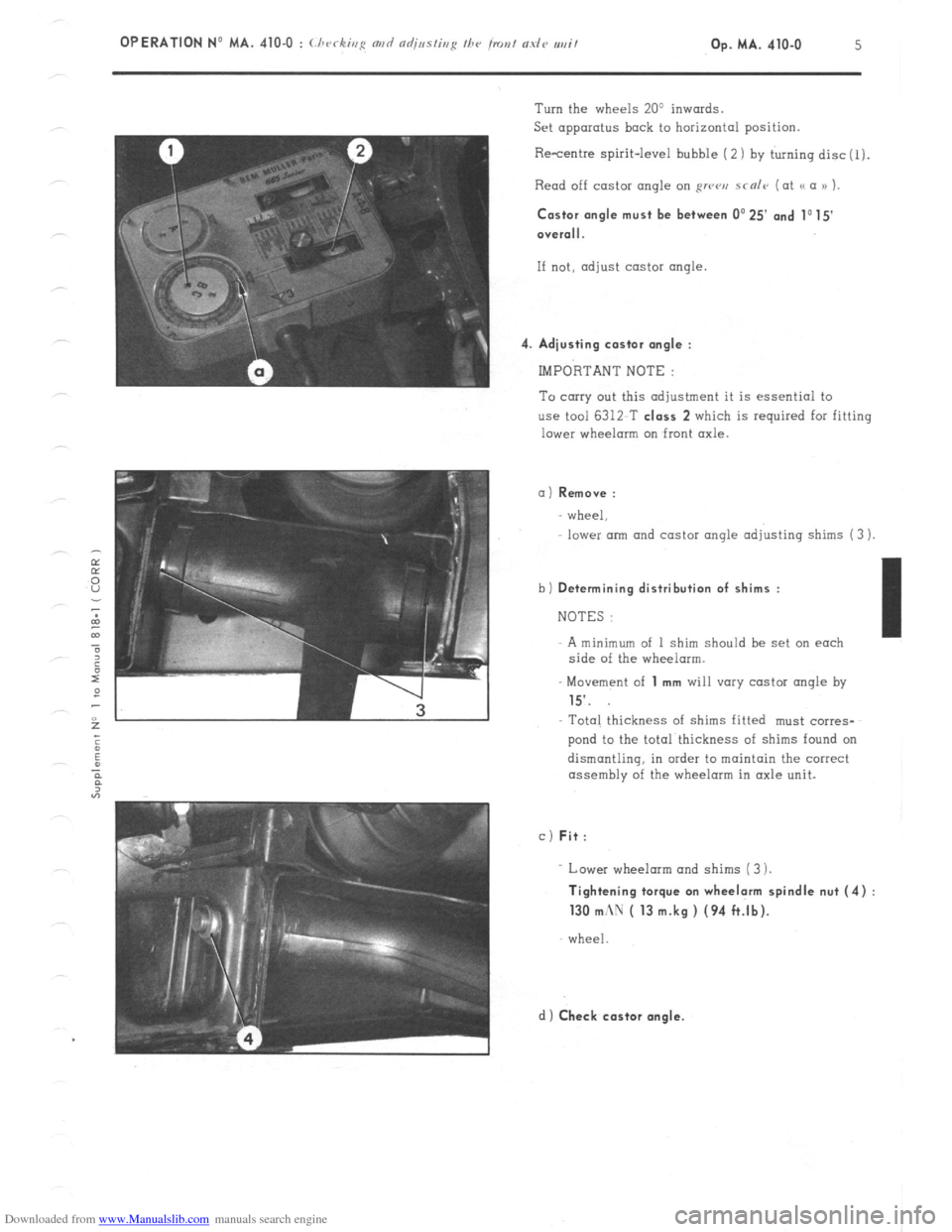
Downloaded from www.Manualslib.com manuals search engine 4 Turn the wheels 20’ inwards.
Set apparatus back to horizontal position.
Resentre spirit-level bubble ( 2) by turning disc(l).
Read off castor angle on RWCJ,J scnlr (at a a )) ).
Castor angle must be
between 0’25’ and 1015
O”erall.
If not, adjust castor angle
Adiusting castor angle :
IMPORTANT NOTE :
To carry out this adjustment it is essential to
use tool 6312 T class 2 which is required for fitting
lower wheelorm on front axle.
a) Remove :
wheel,
lower arm and castor angle adjusting shims (3 )
b)
Determining distribution of shims :
NOTES :
A minimum of 1 shim should be set on each
side of the wheelarm.
- Movement of
1 mm will vary castor angle by
15’.
Total thickness of shims fitted must corres-
pond to the total thickness of shims found on
dismantling, in order to maintain the correct
assembly of the wheelarm in axle unit.
c) Fit:
Lower wheelarm and shims (3 ).
Tightening torque on wheelarm spindle nut (4)
130 mc\U ( 13 m.kg ) (94 ft.lb).
wheel
d) Check castor angle.