engine Citroen CX 1981 1.G Workshop Manual
[x] Cancel search | Manufacturer: CITROEN, Model Year: 1981, Model line: CX, Model: Citroen CX 1981 1.GPages: 394
Page 211 of 394
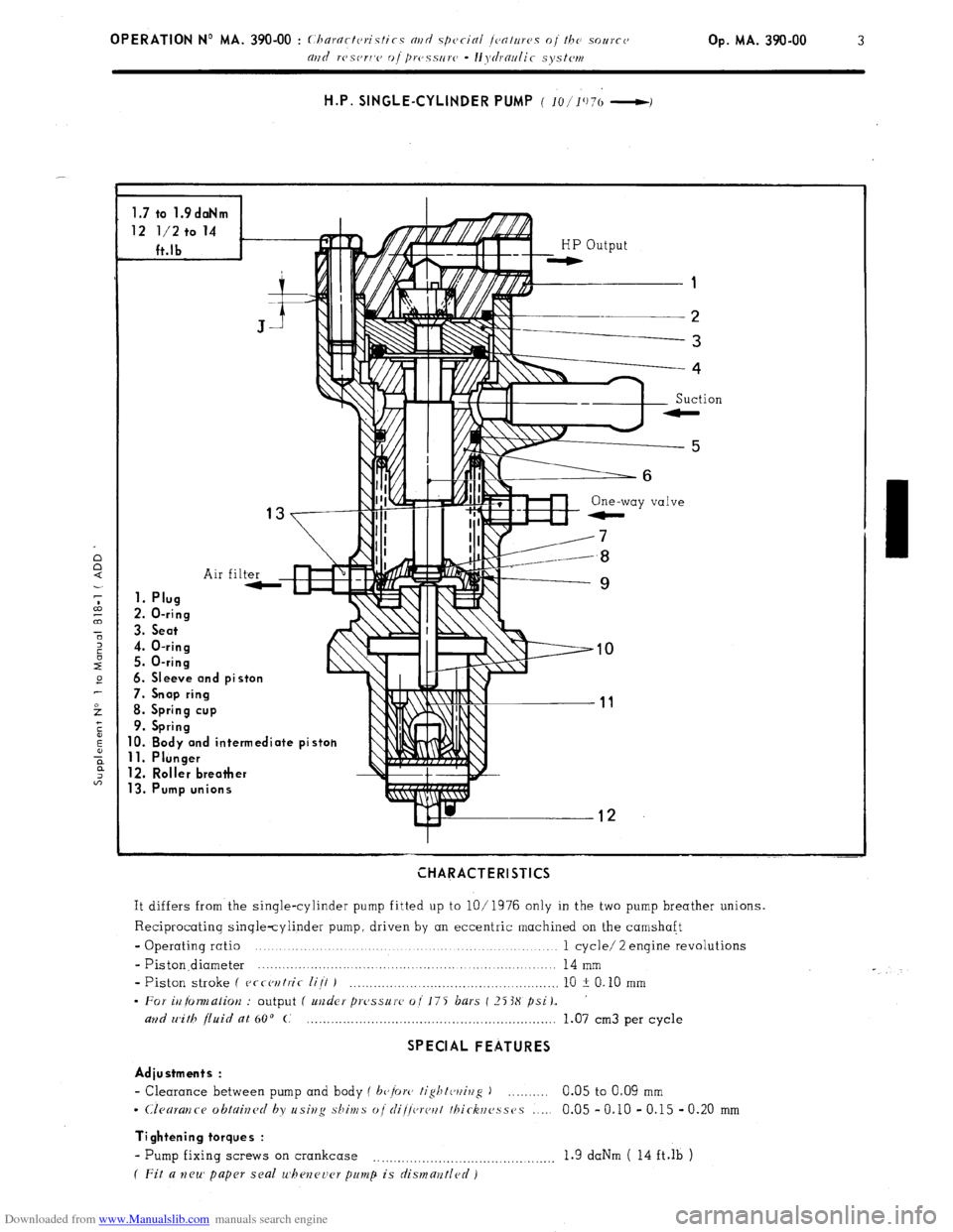
Downloaded from www.Manualslib.com manuals search engine H.P. SINGLE-CYLINDER PUMP ( 10/‘1’)7(, -I
1.7 to 1.9daNm
12 l/2 to 14
ft.lb
1. Plua
2.0-= -ring
3. Seat
4. O-ring
5. O-ring
6. Sleeve and piston
7. Snop ring
8. Spring cup
9. Spring
10. Body and intermediate pist
11. Plunger
12. Roller breather
13. Pump unions
HP output
1
2
------3
One-way
e-
iI 7
.uH-.!.a
e
10
tn 11
ion
CHARACTERISTICS
It differs from the single-cylinder pump fitted up to lO/ 1976 only in the two pump breather unions.
Reciprocating single-cylinder pump, driven by an eccentric machined on the camshaft
- Operating ratio .._._._....._........ 1 cycle/ 2 engine revolutions
- Piston.diameter .._...................
14 mm
- Piston stroke I
ecrcwtric lijt J _......__._........_.._...,_........,._.._._...___,, 10 2 0.10 mm
- For iu fomalior~ : output ( unJer prc’ssure oil75 bars (2F3X psi),
and with fluid at 60’ C _.__.._______.._.___._.___,........_._....__.__.._............ 1.07
cm3 per cycle
SPECIAL FEATURES
Adiustments :
- Clearance between pump and body ( b+rc, tightwivg ) 0.05 to O-09 mm
- Clearartce obtained by usivg shims ojrli/!vrcrtt thirhc~sses 0.05 - 0.10 - 0.15 - 0.20 mm -,..
Tightening torques :
- Pump fixing screws on crankcase . . . . . . . . . ..__._.._.._...._...__.........._.,. 1.9 dab ( 14 ft.& )
( Fit a neu’ paper seal u’bencucr p~unp is dismant/cd)
Page 212 of 394
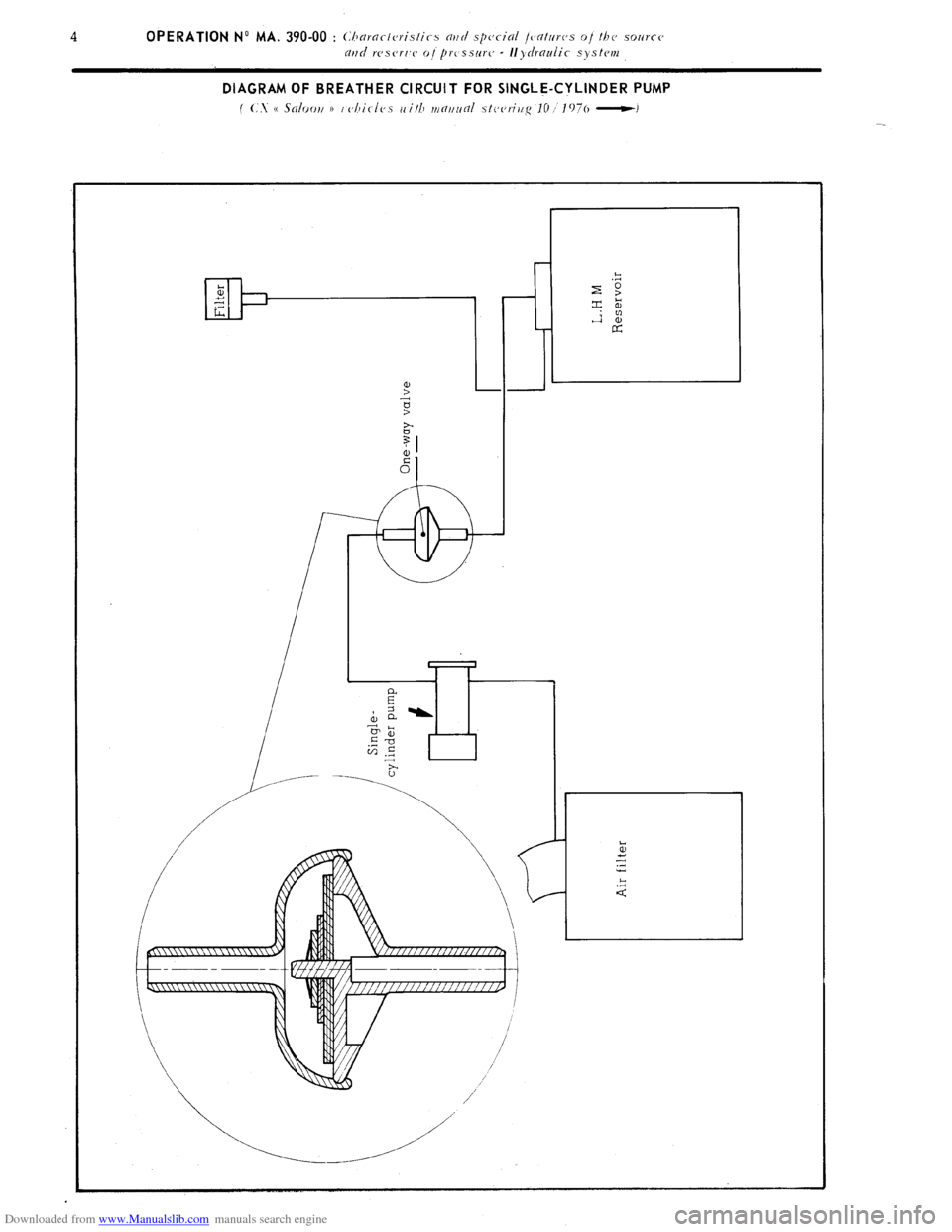
Downloaded from www.Manualslib.com manuals search engine DIAGRAM OF BREATHER CIRCUIT FOR SINGLE-CYLINDER PUMP
f (:. e Saloori 1) i cjhirles with mf7~7~inl stcjeriiig IO I 1976 -1
Page 213 of 394
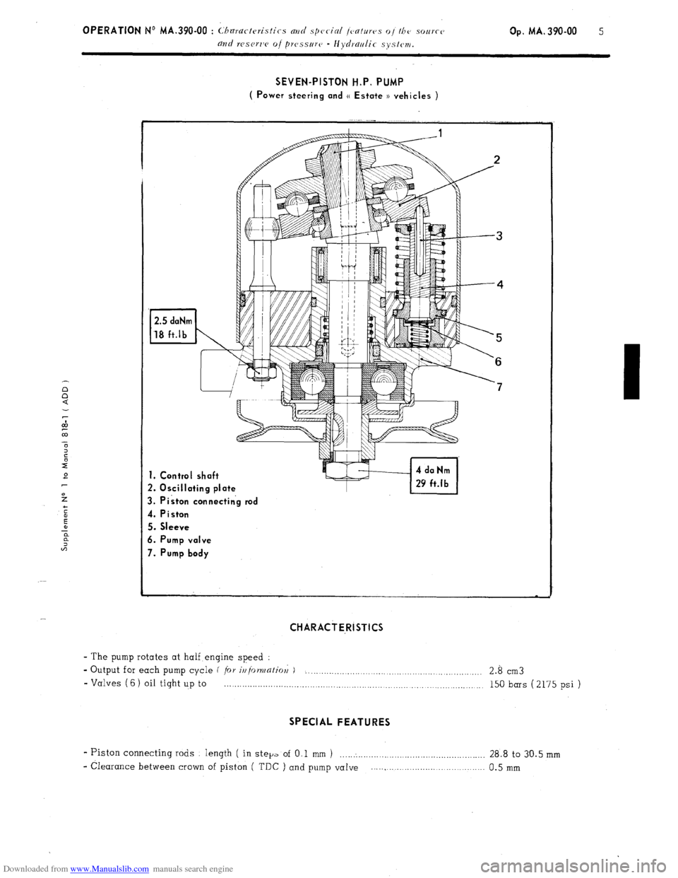
Downloaded from www.Manualslib.com manuals search engine SEVEN-PISTON H.P, PUMP
( Power steering and (( Estate )) vehicles )
1. Control shaft
2. Oscillating plate
3. Piston connectin’g rod
4. Piston
5. Sleeve
6. Pump valve
7. Pump body
CHARACTE,RISTICS
- The pump rotates at half engine speed :
- Output for each pump cycle f
/or ir/{orv/afiol; ) . . . . . . . . . . .._.._........._.........._.........._............. 2.8 cm3
- Valves (6) oil tight up to . . . . . . . . . . . . . . . . . . . . . . . . . . . . . . . . . . . . . . . . . . . . . . . . . . . . . . . . . . . . . . . . . . . . . . . .._._....... 150 bars (2175 psi )
SPECIAL FEATURES
- Piston connecting rods length ( in step of O,l mm 1 ......................................................... 28.8 to 30.5 mm
- Clearance between crown of piston ( TDC ) and pump vaIve ..... , ...................................... 0.5 mm
Page 214 of 394
Downloaded from www.Manualslib.com manuals search engine 6 OPERATION No MA, 390.00 : C1 ,ararteristics
ad special fratuws oj the source
apfd rescr7,e o/ pressur(~ - Hydraulic system.
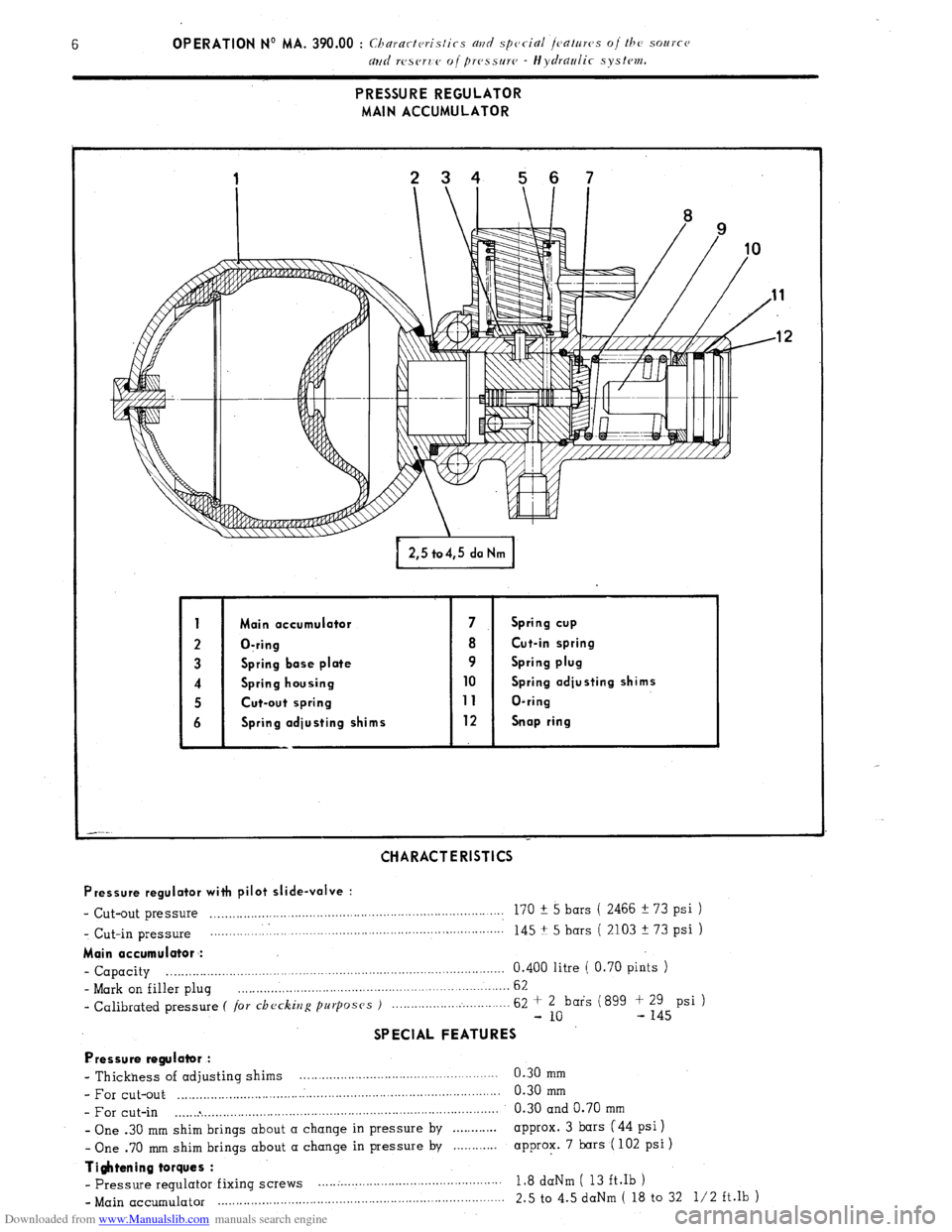
PRESSURE REGULATOR
MAIN ACCUMULATOR
Main occumulotor 7 Spring cup
O-ring 8 Cut-in spring
Spring base plate 9 Spring plug
Spring housing 10 Spring adjusting shims
Cut-out spring 11 O-ring
Spring odjusting shims 12 Snap ring
CHARACTERISTICS
Pressure regulator with pilot slide-valve :
- Cut-out pressure . .._......,_....____.............,.,......................................... 170 f 5 bars ( 2466 !I 73 psi ) _ Cut-in pressure __.....___.__.,..,.....,..,................,,...................................
145 + 5 bars ( 2103 + 73 psi )
Main accumulator :
- Capacity . . . . 0.400 litre ( 0.70 pints )
- Mark on filler plug . . , 62
- Calibrated pressure C /or checking purposes ) 62 + 2 bars (899 f 29 psi )
- 10 - 145
SPECIAL FEATURES
Pressure regulator :
- Thickness of adjusting shims . 0.30 mm
- For cut-out ..I.._......._..... .._. ,. .._. .:.. ,. ,. ..__.. ,. ..__ ,. ,. ._ ._.. .___ 0.30
mm
- For cut-in .._.... * .__....._._.,.,.,._.,....................................... 0.30 and 0.70 mm
- One .30 mm shim brings about a change in pressure by . . . . . . . . . . , approx. 3 bars (44 psi 1
- One .70 mm shim brings about a change in pressure by . . . . . . . . . approx. 7 bars ( 102 psi )
Ti$ttening torques :
- pressure regulator fixing Screws . . . . .._.__.....__._............................... 1.8 daNm ( 13 ft.Ib )
- Main accumulator ..,.. ,. . . ,. __ . . . . .._. ., ,__. ._ __ 2.5 to 4.5 daNm ( 18 to 32 l/2 ft.lb )
Page 215 of 394

Downloaded from www.Manualslib.com manuals search engine Op. MA. 390.00 i
DIAGRAMS OF OPERATION
CUT-OUT
1 a hydou ic CI~CIII!
f
Page 216 of 394
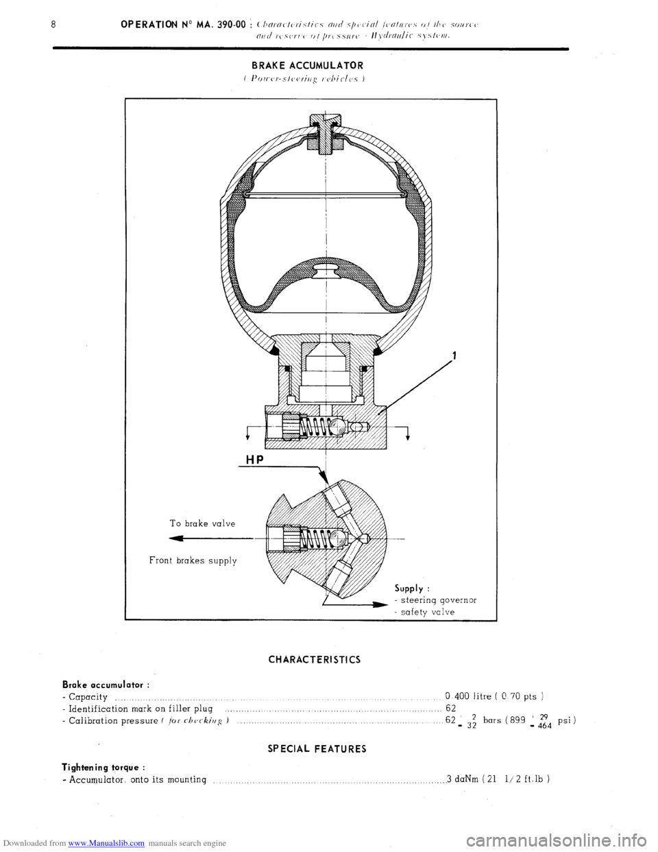
Downloaded from www.Manualslib.com manuals search engine BRAKE ACCUMULATOR
1 I’r~rc~(,r-s!(,(,riri~ I cbic-lcc5 J
HP
To brake valve
--
Front brakes supply Supply :
- steering governor
- safety valve CHARACTERISTICS
Brake accumulator :
- Capacity .._._._.._.._.___._____._._._..__........ _._____ _......._._.___._ _____..____.___ ___._._._._._._. 0 400 litre ( C. 70 pts )
- Identification mark on filler plug ,...........
62
- Calibration pressure f /or rhc,c-kir/~ J 62 _ 3z bars ( 899 1 dTd psi ) SPECIAL FEATURES
Tightening torque :
- Accumulator. onto its mounting .,..... .., .._.. .._.. .._....._._._. 3 daNm ( 21 l/ 2 ft.lb )
Page 217 of 394
Downloaded from www.Manualslib.com manuals search engine Op. MA. 390.00 9
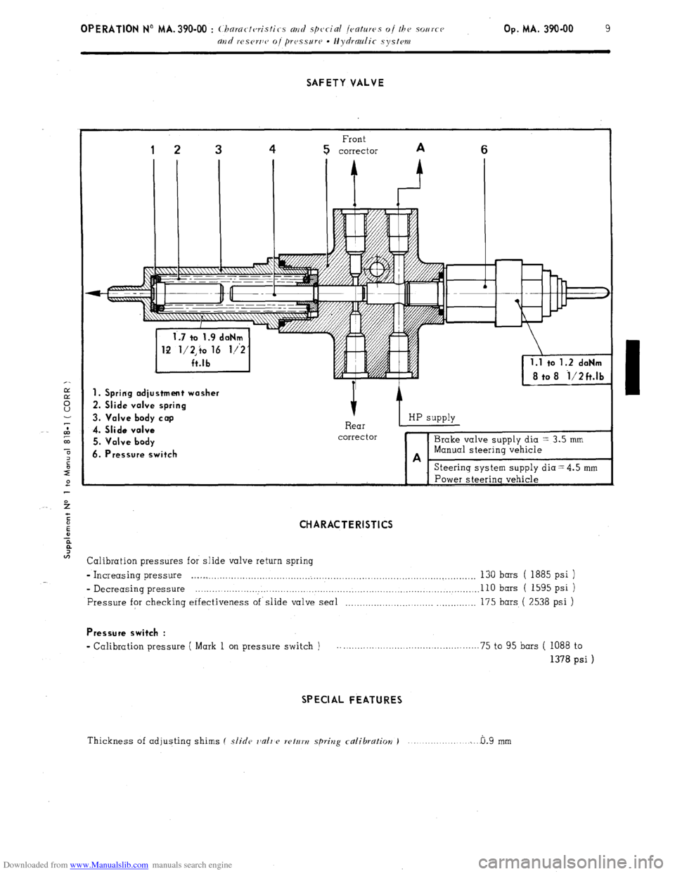
SAFETY VALVE
Front
1 2 3 4 5 corrector A 6
i 8 to 8 i/2ft.lb
1. Spring adjustment washer
2. Slide valve spring
3. Valve body cap
4. Slide valve
5. Valve body
6. Pressure switch 1 HP SWP~Y I-
corrector
Steering system supply diaz4.5 mm
CHARACTERISTICS
Calibration pressures for slide valve return spring
- Increasing pressure .l~lOs _._..........__...._,..__._....,..__..__.__.,...___........._...._...,__..._.._.,,.._.,...,.... 130 bars ( 1885 psi )
- Decreasing pressure . . . . . . . . . .._.. I ~...~~~....~.~.....~.~.~.~.~.~~~.~.~....~.~~~~.....~~~..~..~....~~.~~...~.~.. 110 bars ( 1595 psi )
Pressure for checking erfectiveness of’slide valve seal .,_._._.,__._._...,._._.,....__ _,..,..,_.___. 175 bars ( 2538 psi )
Pressure switch :
- Calibration pressure ( Mark 1 on pressure switch ) .._.............._.............._............. 75 to 95 bars ( 1088 to
1378 psi )
SPECIAL FEATURES
Thickness of adjusting shims ( slide rlalrzc wturtj spriv2g calibration i 0.9 mm ...._.__..._....,..._.i___
Page 218 of 394
Downloaded from www.Manualslib.com manuals search engine 10 OPERATION No MA. 390-00 : Churarteristics and special features oi the source
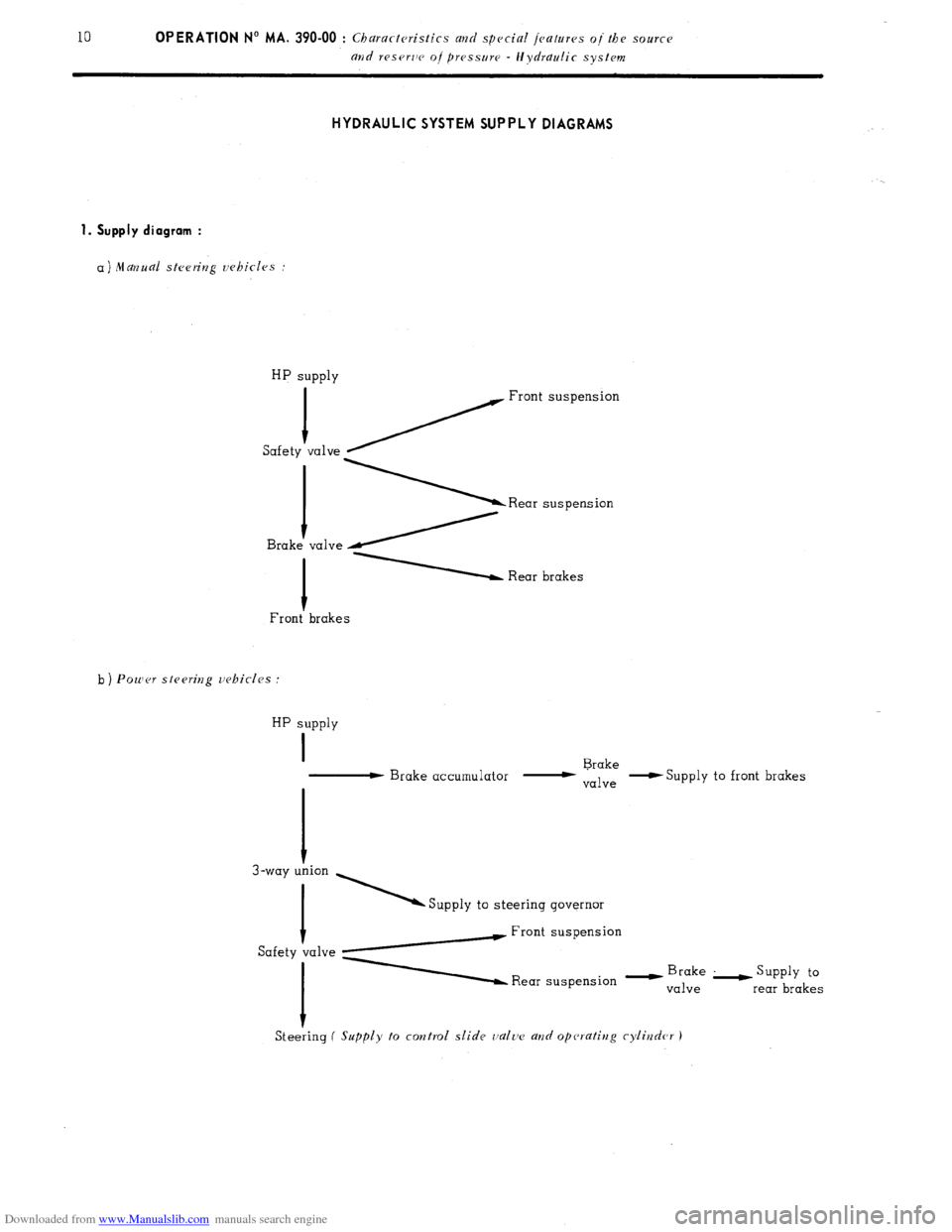
and reserlv oj pressure - Hydraulic system HYDRAULIC SYSTEM SUPPLY DIAGRAMS
1. Supply diagram :
a) Manual steering vehicles :
HP supply
1
Safety ~ Front suspension
va1ve \Rear suspension valve /
1 Rear brakes
Front’ brakes
b ) Power stesritzg vehicles :
HP supply
I
- Brake accumulator - Brake
valve -S
upply to front brakes
I
3-way T ’ Supply to steering governor
Safety talve yw Front suspension
A Rear suspension - y”,;“,“,’ L supp1y to
rear brakes
Steeiing
( Supply to control slide valtv a?zd operating cylirzder J
Page 219 of 394
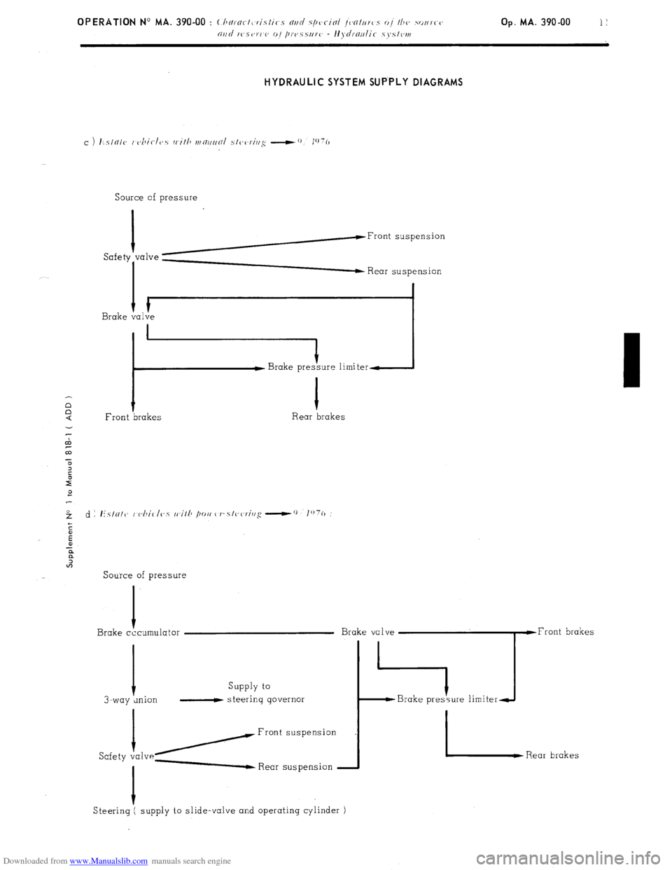
Downloaded from www.Manualslib.com manuals search engine HYDRAULIC SYSTEM SUP.PLY DIAGRAMS
Source of pressure
I
h-Front suspension
Safety “‘lve ; Rear suspension
I
I Brake valve
i :ure limiter-
1
Front brakes Rear brakes
Source of pressure
I
Brake cccumulator
Supply to
I-way wion - steering governor
/Front
Safety va1ve- Rear suspension
I
Steering ( supply to slide-valve and operating cylinder )
Page 220 of 394
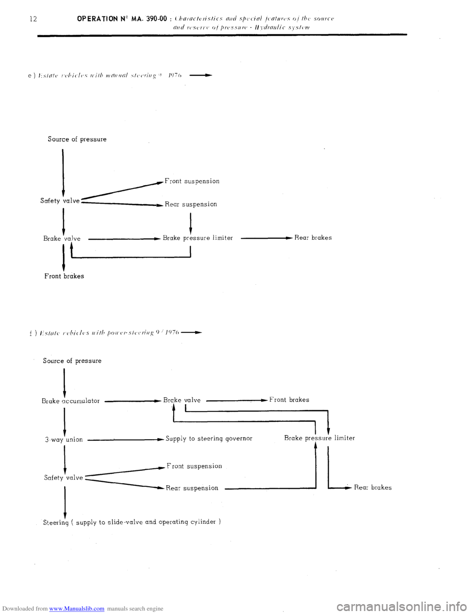
Downloaded from www.Manualslib.com manuals search engine Source of pressure
Safety ialveYFront suspension
t
L Rear suspension
I I
Brake valve w Brake pressure limiter w Rear brakes
I t
Front ‘brakes
Source of pressure
I
Brake accumulator
I
3-way union F Brake valve w Front brakes
Supply to steering governor
Safety I
va1ve y Rear suspension
I
Steering ( supply to slide-valve and operating cylinder )