Citroen CX 1982 1.G Workshop Manual
Manufacturer: CITROEN, Model Year: 1982, Model line: CX, Model: Citroen CX 1982 1.GPages: 394
Page 201 of 394
Downloaded from www.Manualslib.com manuals search engine 12 OPERATION NP MA. 330.00 : (haro? gvmhr,, III. DRAINING AND REFILLING THE GEARBOX AND THE CONVERTER
1. Place the vehicle over a pit 01 on a ramp
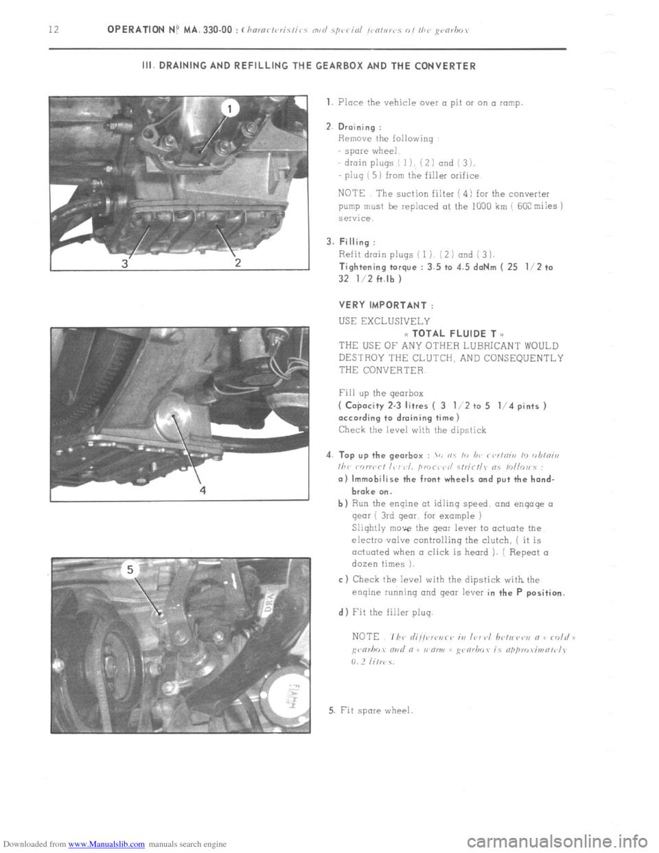
2. Draining :
Remove the following
spare wheel
drain plugs ( I), ( 2 I and i 3 ),
plug ( 5) from the filler orifice
NOTE The suction filter ( 4) for the converter
pump must be replaced at the 1000 km ( 60C miles j
service.
3. Filling :
Refit drain plugs ( 1). (2 1 and ( 3 1.
Tightening torque : 3.5 to 4.5 daNm ( 25 l/2 to
32 l/2 ft.lb )
VERY IMPORTANT :
USE EXCLUSIVELY
(< TOTAL FLUIDE T o
THEUSEOFANYOTHERLUBRICANTWOULD
DESTROY THE CLUTCH, AND CONSEQUENTLY
THE CONVERTER
Fill up the gearbox
( Co$acity 2-3 litres ( 3 l/2 to 5 l/4 pints )
according to draining time)
Check the level with the dipstick
4. Top up the gearbox :
> nc I<, b<’ r<,r/niii 10 <,hini,,
I/><,
broke on.
b) Run the engine at idlinq speed, and engage 01
gear ( 3rd gear, for example )
Slightly move the gear lever to actuate the
electro .valve controlling the clutch, ( it is
actuated when a click is heard ). ( Repeat a
dozen times ).
c) Check the level with the dipstick with the
enqine running and gear lever in the P position.
d) Fit the filler plug.
5. Fit spore wheel
Page 202 of 394
Downloaded from www.Manualslib.com manuals search engine OPERATION No MA. 330-00 : (hnrnctc,ristic-s NII~ spc,rioi !c c?/uws 01 lhc godms. Op. MA. 330-00 13
FIVE-SPEED MANUAL GEARBOX
I. CHARACTERISTICS
Gear ratids :
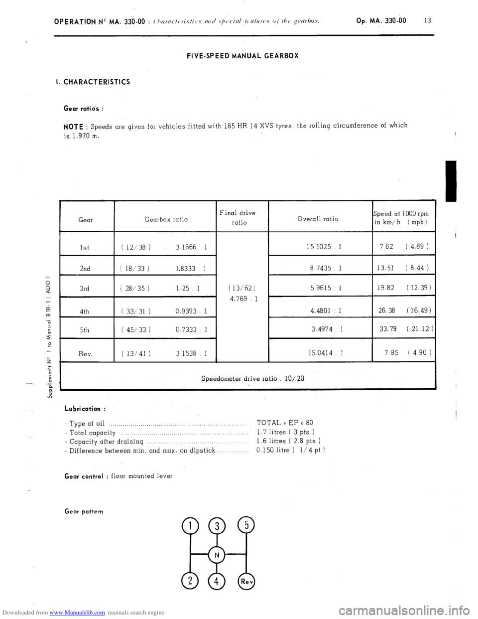
NOTE : Speeds are given for vehicles fitted with 185 HR 14 XVS tyres, the rolling circumference of which
is 1.970 m.
Gear Gearbox ratio Final drive
ratio Overall ratio Speed at 1000 rpm
in km/h (mph)
1st ( 12138 ) 3.1666 1 15 1025 1 7 82 ( 4.89 )
2nd ( 18/33 ) I..8333 1 8.7435 1 13.51 ( 8.44 )
3rd i 28/35 1 1.25 1 ( 13/62) 5.9615 1 19.82 ( 12.39)
4.769 1 ’
4th ( 33131 ) 0.9393 1 4.4801 : 1 26.38 (16.49)
5th ( 45/ 33 1 0.7333 1 3.4974 1 33.79 ( 21 12 )
Rev. ( 13/41 1 3 1538 1 15.0414 1 7.85 ( 4.90 )
Speedometer drive ratio lo/20
,
Lubrication :
Type of oil .._.. .._. ,__.._. ...,... ,. ,. ,.. ._. _.. TOTAL (( EP )) 80
Total capacity .._......._.. .._._.. _._......_... _.. 1.7 litres ( 3 pts )
- Capacity after draining .._._.._..... _....._._..,. _...... 1.6 litres ( 2.8 pts )
- Difference between min. and max. on dipstick 0.150 litre ( l/4 pt
1
I
! Gear control
: floor mounted lever Gear pattern
5 -8 Rev
Page 203 of 394
Downloaded from www.Manualslib.com manuals search engine ii. SPECIAL FEATURES
Adjustments :
- Endfloat of lW2nd gear synchio nuts
0.05 mm max.
- Endfloot of half-ring between 2nd and 3rd gear pinions GO5 mm mox
- Clearance between bearing split pin and gearbox casing
0.05 mm nlax.
- Overall prelood on differential bearinq
0.15 mnl Adjusting the selector shaft stops :
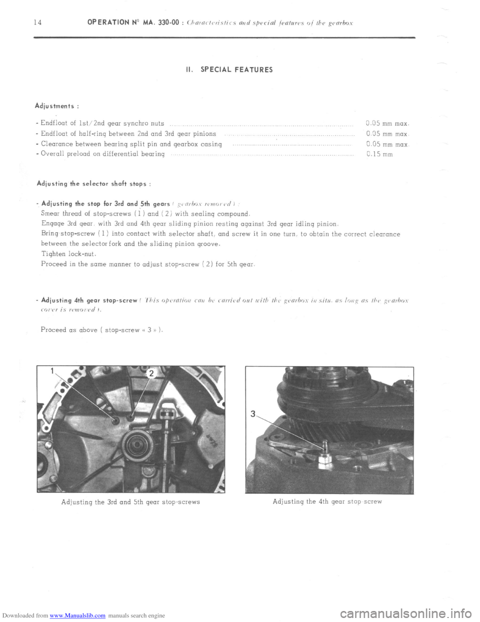
. Adjusting the stop for 3rd and 5th gears / ,g< nrhov lI~n,r,, vd ,
Smear thread of stop-screws (1 ) and ( 2) with sealing compound.
Engage 3rd qear with 3rd and 4th qeor sliding pinion resting against 3rd gear idling pinion.
Bring,stop-screw ( 1) into contact with selector shaft, and scw.v it in one turn, to obtain the correct clearance
between the selector fork and the sliding pinion groove.
Tighten lock-nut.
Proceed in the some manner to adjust stop-screw ( 2) for 5th qear.
Adjusting the 3rd and 5th gear stop~screws
Page 204 of 394
Downloaded from www.Manualslib.com manuals search engine FIVE-SPEED MANUAL GEARBOX
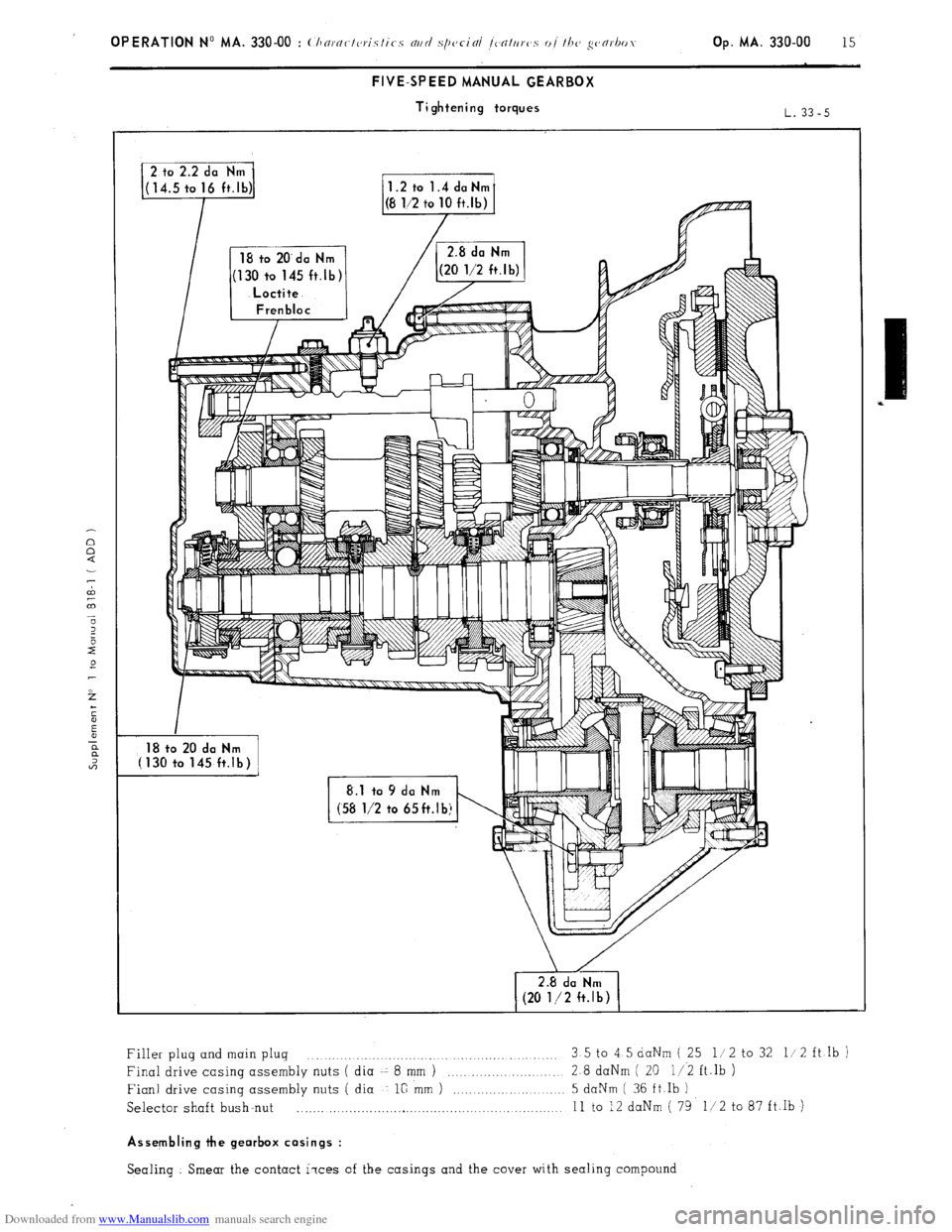
Tightening torques
(130 to 145 ft.lb)
II I lr II III
\/
2.8 da Nm
(20 l/2 ft.lb)
Filler plug and main plug 3.5 to 4 5 daNm ( 25 l/2 to 32 I/ 2 ft Ib )
Final drive casing assembly nuts ( dia -z 8 mm )
.,..._.,. 2.8 daNm ( 21) 11.2 ft.Ib )
Fianl drive casing assembly nuts ( dia l@ mm )
5 daNm ( 36 ft fb )
Selector shaft bush-nut _...... . . . . . .._...._...._...._..__................
11 to 12 daNm ( 79 l/2 to 87 ft.Ib )
Assembling the gearbox casings :
Sealing Smear the contact i?ces of the casings and the cover with sealing compound
Page 205 of 394

Downloaded from www.Manualslib.com manuals search engine 16
FIVE-SPEED MANUAL GEARBOX
( Adjustment shims )
L. 33-5
1.41 - 1.46 - 1.51-
1.56 - 1.61
.- 1.66-
R I
1.49-l .52-l .55-l .58
from 4.25 to 5.65
Page 206 of 394

Downloaded from www.Manualslib.com manuals search engine Op. MA. 330-00 17
FIVE-SPEED MANUAL GEARBOX
( gear sequence )
1 st gear
2nd gear
3rd gear
4th gear
5th gear
Reverse gear
Page 207 of 394

Downloaded from www.Manualslib.com manuals search engine OPERATION No MA. 344-O : Adjusting thy gcarbor con/ro/s. Op. MA: 344.0 1
ADJUSTING THE GEAR LEVER
(I) the lever should be inclined approximately 3’
towards the rear in relation to the vertical axis
XX’ of the vehicle.
If not :
remove dust cover ( 1 ),
remove three screws ( 2 ),
shift cover ( 3 ) to obtain correct position of
gear lever.
NOTE : Should it be impossible to effect odjust-
merit by means of cover (3 ), make necessary
adjustment at control shaft hall joint (5 ).
Tighten three screws (2 ).
Refit dust cover (1 ). b)
the gear lever should be located in the longitu-
dinal axis YY’ of the vehicle.
If not :
= Adjust selector shaft boll joint (4) to obtain
this position.
NOTE :
When adjusting boll joints (4) 01 i 5) it is
imperative that the flats (v)
on each shaft ore properly aligned.
Page 208 of 394

Downloaded from www.Manualslib.com manuals search engine DRIVE SHAFTS
OPERATION No MA. 372-00 : Cbaractcristics and sp
I
E 0
U RIGHT-HAND-DRIVE SHAFT
L. 37-2
1 S ft.lb 1 65 ft.lb
1 I; CHARACTERISTICS
- 1 co,nstant velocity ball-joint at wheel end
i 1 tri-axe joint at gearbox end Y = 423 mm ( 4-q gearbox )
Y = 388 mm ( 5-sp. gearbox ) II. SPECIAL FEATURES
Lubrication :
--TOTAL MULTIS MS grease
Page 209 of 394
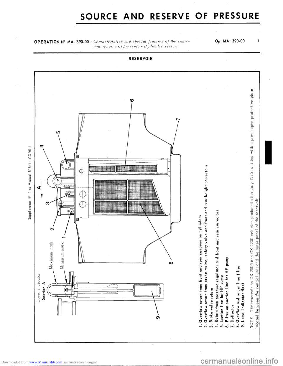
Downloaded from www.Manualslib.com manuals search engine Supplement NC 1 to Manual 818-l f CORR )
Level indicator
Section A
Maximum mark
Minimum mark
1. Overflow return from front and rear suspension cylinders
2. Overflow return from brake valve, safety valve and front and rear height correctors
3. Brake valve return
4. Return from pressure regulator and front and rear correctors
5. Suction line for HP pump
6. Filter on suction line for HP pump
7. Deflector
8. Overflow and return line filter
9. Level indicator float
NOTE The reservoir on CX 2000 and CX 2200 vehicles produced after July 1375 is fitted with a pre-shaped protective plate
located between the central unit and the outer uanel of the reservoir
Page 210 of 394

Downloaded from www.Manualslib.com manuals search engine HIGH PRESSURE SINGLE CYLINDER PUMP f-/i, to-0 j
1.7 to 1.9 daNm
12 1/‘2 to 14
ft.lb
1. Plug
2. O-ring
3. Seat
4. O-ring
!i. O-ring
6. Sleeve and piston
7. Snap ring
8. Spring plate
9. Spring
10. Body and intermediate piston
11. Plunger
12. Roller
12
ZESCRIPTiOH
Reciprocating single-cylinder pump, operated by an eccentric machined on camshaft
Operating ratio ,.
_..__.,.,..._.. . . . . . . . . . . . . :... ,. 1 cycle/ 2 engine revolutions
-
- Piston diameter .._....._.....,,.......,............. .,.,.,.,... .,. 14 mm
- Piston stroke ( (‘c-c c,///rrc~ /if/ ) ,. ,,... ‘10 t 0.10 mm
.._..... ..,....,.,............. ..I.
- HI ,,‘OJJ f~ji,~c/icntin~f : output (111fr1cr /on{1 of I75 1~nr.s.
/ictirl f/f (10” (. i.. 1.07 cm3per cycle
SPECIAL FEATURES
Tightening torques :
- Pump fixing screw on crankcase .._.....,.._._..,.....,.............. .._,__. _. _.. .._......_........ 19 mN ( 1.9 m.kg) ( 14ft.b)
( Fit a ,~c,~I’ paper sc~nl ~r,hcvc,r’c~~ pzrmp is dismar~tld~ -