Citroen CX 1982 1.G Workshop Manual
Manufacturer: CITROEN, Model Year: 1982, Model line: CX, Model: Citroen CX 1982 1.GPages: 394
Page 261 of 394
Downloaded from www.Manualslib.com manuals search engine I. MANUAL STEERING
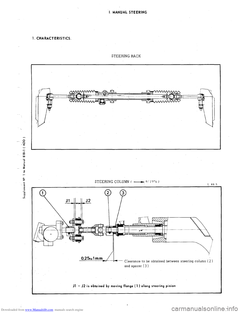
1. CHARACTERISTICS.
STEERING RACK
STEERING COLUMN ( -,
q/1976 )
I. 44.5
Clearance to be obtained between steering column ( i )
and spacer (3 )
Jl = J2 is obtained by moving flange (1 ) along steering pinion
Page 262 of 394
Downloaded from www.Manualslib.com manuals search engine STEERING COLUMN ( ‘11’ l’)‘o -1
L.44-21
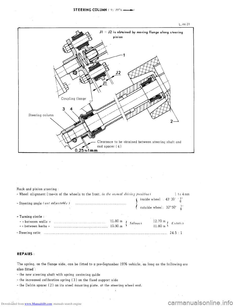
Jl = J2 is obtuined by moving flange along steering
pinion
Steering co1
Clearance to be obtained between steering shaft and
mind spacer (4)
1 a
Rack and pinion steering :
- Wheel alignment ( toe-in of the wheels to the front, i/z, /bc~ rtot~/nl rlrir,ir/g posifiort I 1 tk) 4 mm
inside wheel 43’30’
1”
- Steering angle (Ilot djustahlc~ ) 0
outside wheel : 32’50’ i’
- Turning circle :
- CC between walls )) Il.80 m
I Snloo~2 s 12.70 m
.
(! Estntc’s
- CC between kerbs )I
. . . . . ..__.._........................................,.,.. 10.90.m 11.80 m
- Steering ratio, .-.......................-............................................................................................................ 24.5 : 1
REPAIRS :
The spring, on the flange side, can be fitted to a preSeptember 1976 vehicle,‘as long as the following are
also fitted -:
- the new steering shaft with spring centerinq guide
- the increased calibration spring ( 3 ) on the fixed support side
- the Delrin spacer (2) on its steel mounting plate. at the steering wheel end.
Page 263 of 394
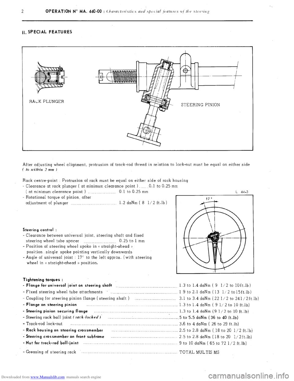
Downloaded from www.Manualslib.com manuals search engine ll, SPECIAL FEATURES
STEERING PINION
After adjusting wheel alignment, protrusion of track-rod thread in relation to lock-nut must be equal on either side
( .to within 2 mm )
Rack centre-point Protrusion of rack must be equal on either side of rack housing
- Clearance at rack plunger ( at minimum clearance point ) .O.l to 0.25
( at minimum clearance point ) ., .,...._...... .._._ 0 1 to 0.25 mm
- Rotational torque of pinion, after
adjustment of plunger .._..... .._.... 1.2 daNm ( 8 l/2 ft.lb)
L 44.3
Steering control :
- Clearance between universal joint, steering shaft and fixed
steering wheel tube spacer 0.25 to 1 mm
.._....__._..._.... ._..__..
- Position of steering wheel spoke in (( straight-ahead ))
position. single spoke pointing vertically downwards
- Angle of universal joint : 17” to the left approx. (with steering
wheel in (( straight-ahead )) position.
- Coupling for steering pinion flange ( steering shaft ) ....................................
- Flange on steering pinion ................................................................................
- Steering pinion securing flange ........................................................................
- Steering rack ball joint f rack Jacked )’ .............................................................
- Track-rod lock-nut ..............................................................................................
- Rack housing on steering crossmember ..........................................................
-. Steering crossmember on front subframe ..........................................................
- Nut for track-rod ball-joint ................. ................................... ..... ...................... Tightening torques :
- Flange for universal joint on steering shaft __..._.__.._._.........,.........................,. 1.3 to 1.4 daNm ( 9 11 2 to
lOft.lb)
- Fixed steering wheel tube attachments
. . . . . . . . . . . . . . . . . . . . . 1 9 to 2.1 daNm (13 l/2 to15ft.lb)
3.1 to 3.4 daNm (22 l/2 to 241/2ft,lb)
1.3 to 1.4 daNm ( 9 l/ 2 to 10 ft.lb)
1.3 to 1.4 daNm (9 l/2 to 10 ft.lb)
.5 to’5.5 daNm (36 to 40 ft.lb)
3.6 to 4 daNm ( 26 to 29 ft.lb)
2.5 to 2.8 daNm ( 18 to 20 l/2 ft.lb)
2.5 to 2.8 daNm (18 to 20 1/2ft.lb)
9 to 10 daNm ( 65 to 72 l/2 ft.lb)
- Greasing of steering rack TOTAL MULTIS MS
Page 264 of 394
Downloaded from www.Manualslib.com manuals search engine II. POWER STEERING WITH POWERED RETURN
I. CHARACTERISTICS
Hydraulically operated rack and pinion steering Steering
ratio . . . . . . . . . . . . . . . . . . . . . . . . . . . . . . . . . . . . . . . . . . . . . . . . . . . . . . . . . . . . . . . . . . . . . . . . . . . . . . . . . . . . . . . . . . . . . . . . . . . . . . . . . . . . . . . . . . . . . . . . .. 13 5 i
- No of steering wheel turns from lock to lock
. . . . . . . .._._.__................................................ 25
- Turning circle (( between walls ))
11 80m
(.S x00 OIlCi ( s .2x0 solooll.~
(( between kerbs )) 10 90 m t
/( between walls )) 12 70 m
I( between kerbs 1) 11 80 m t I’\/N/l’ N/id I’n~\lix”
- Wheel alignment ( toe-in of wheels to the front i (i/l //I( //r~rjj/rll c/r;/ ii/:: p, cilirJ/i 1 1 to 4 mm
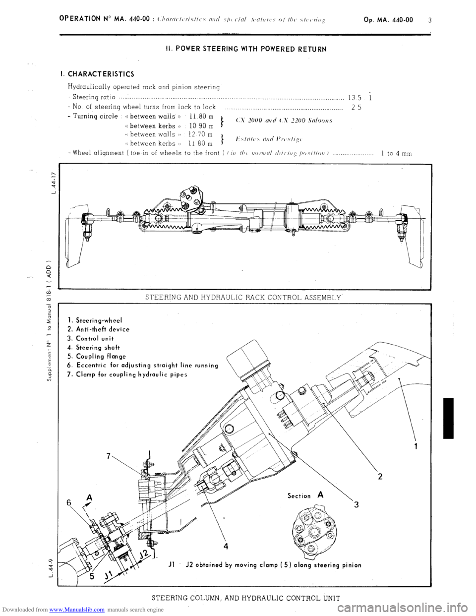
STEERING AND HYDRAULIC RACK CONTROL ASSEMBLY
1. Steering-wheel
2. Anti-theft device
3. Control unit
4. Steering shoft
5. Coupling flonge
6. Eccentric for odjusting stroight line running
7. Clomp for coupling hydraulic pipes
Jl J2 obtoined by moving clomp (5) olo
STEERING COLUMN, AND HYDRAULIC CONTROL UNIT
Page 265 of 394
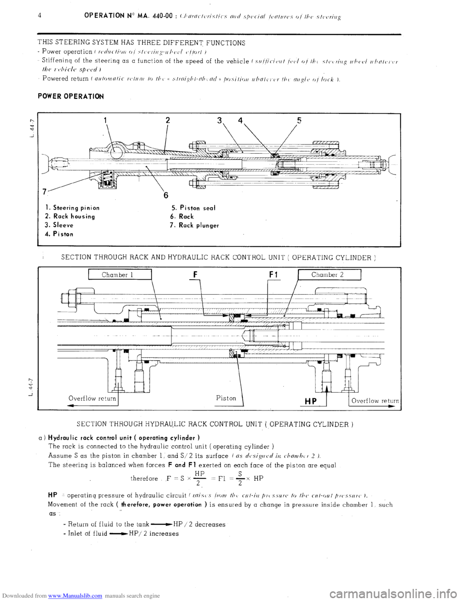
Downloaded from www.Manualslib.com manuals search engine THIS STEERING SYSTEM HAS THREE DIFFERENT FUNCTIONS
- Power operation i rc,d/ic-/ici// 0 I .~/I c,r-i/lg-o /Io.c,/ c’//or/ /
Stiffeninq of the steerinq as a function of the speed of the vehicle f s////it-ic,r/t /<,(,I o/ 11~1 c/c,c~ri/t.cq r/~llc(,I I//JNI(,I or
lhc, 1 cjhicle spc,c~d )
1. Steering pinion 5. Piston seal
2. Rack housing 6. Rack
3. Sleeve 7. Rack plunger
4. Piston
I SECTION THROUGH RACK AND HYDRAULIC RACK CONTROL UNIT ( OPERATING CYLINDER )
SECTION THROUGH HYDRAULIC RACK CONTROL UNIT ( OPERATING CYLINDER )
a) Hydraulic rack control unit ( operating cylinder )
The rack is connected to the hydraulic control unit ( operating cylinder )
Assume S as the piston in chamber 1, and S/ 2
its surface ( ns dcjsiguvd iu c-hmvhc 1’ 2 J.
The steering is balanced when forces F and Fl exerted on each face of the piston are equal
therefore F = S x F =Fl +x HP
HP 1 operatinq pressure of hydraulic circuit f mist s l‘ront /hc r-r/-iit /I,,( s.5~1’~~ lo fhc cf4I-r)ul /~r~~.~.s~ir~~ J.
Movement of the rack ( therefore, power operation ) is ensured by a change in pressure inside chamber 1, such
as
I Return of fluid to the tank -HP / 2 decreases
- Inlet of fluid -HP/ 2 increases
Page 266 of 394
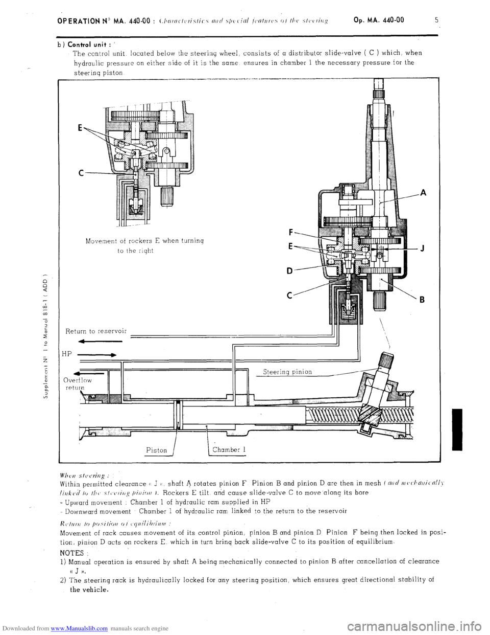
Downloaded from www.Manualslib.com manuals search engine b) Control unit : ’
The contra! unit located below the steering wheel, consists of a distributor slide-valve ( C ) which. when
hydraulic pressure on either side of it is the same ensures in chamber 1 the necessary pressure for the
steerinq piston
Movement of rockers E when turning
to the riqht
F
E
D
C
Return to reservoir
HP
QV re Wh <‘,I s I? cw%g .’
Within permitted clearance (1 J ):, shaft A rotates pinion F Pinion B and pinion D are then in mesh f NII~/ nl(,<.l1~)ji(nll>~
lillk cd lo II1 1’ ~/~~c,~i/lg /~ir/io/l 1. Rockers E tilt, and cause slide-valve C to move.along its bore
_ Upward movement : Chamber 1 of hydraulic ram supplied in HP
- Downward movement Chamber 1 of hydraulic ram linked to the return to the reservoir
lic,Inr~i lo fm.silio~i 0 I ~~yiiilihrif~vf
Movement of rack causes movement of its control pinion. pinion B and pinion D Pinion F being then locked in posi-
tion, pinion D acts on rockers E. which in turn brinq back slide-valve C to its position of equilibrium.
NOTES :
1) Manual operation is ensured by shaft A being mechanically connected to pinion B after cancellation of clearance
a J )).
2) The steering rack is hydraulically locked for any steering position, which ensures great directional stability of
the vehicle.
Page 267 of 394
Downloaded from www.Manualslib.com manuals search engine 6
OPERATION No MA. 440-00 : (.hnrcrc-tcrislics nrtd .s/)oc-in/ /c~n/trr(~s o/ I/I(~ .s/(,(zri,~g
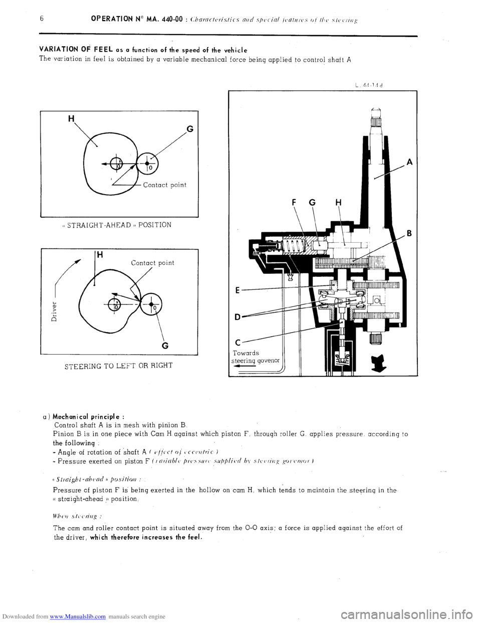
VARIATION OF FEEL as a function of the speed of the vehicle
The variation in feel is obtained by a variable mechanical force being applied to control shaft A
1~ STRAIGHT-AHEAD 1) POSITION
Contact point
STEERING TO LEFT OR RIGHT Towards
a)
Mechanical principle :
Control shaft A is in mesh with pinion B
Pinion B is in one piece with Cam H against which piston F, through roller G. applies pressure. according to
the following
- Angle of rotation of shaft A ( r,//‘c’cf oj
tjcct,utric )
* Pressure exerted on piston F ( I nricrhlc> /)r(,ssur( supplic~d In stc,~,ririg go('~'nlor J
Pressure of piston F is being exerted in the hollow on cam H, which tends to maintain the steering in the
(( straight-ahead !j position‘
The cam and roller contact point is situated away from the O-O axis; a force is applied against the effort of
the driver,
which therefore increases the feel.
Page 268 of 394
Downloaded from www.Manualslib.com manuals search engine d
m
.-
0
2
f Op. MA. 440-00
7 -
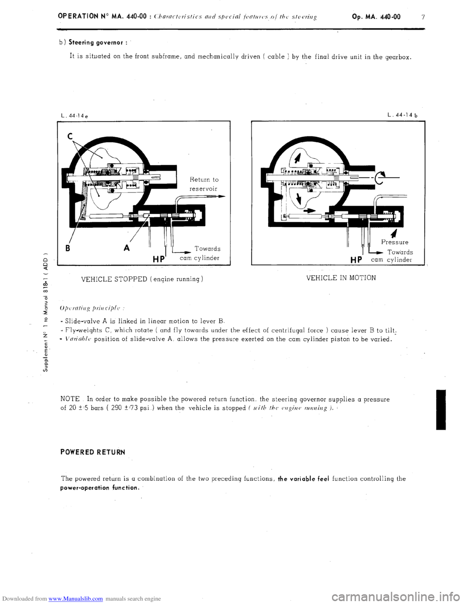
b) Steering governor :
It is situated on the front subframe, and mechanically driven ( cable ) by the final drive unit in the gearbox.
Ei A ”
VEHICLE STOPPED (engine running)
L.44-14b
I/ /II I Pressure
IL Towards
HP cam cylinder
VEHICLE IN MOTION
* Slide-valve A is linked in linear motion to lever B
- Fly-weights C, which rotate ( and fly towards under the effect of centrifugal force ) cause lever B to tilt.
=
L'nrioblc, position of slide-valve A, allows the pressure exerted on the cam cylinder piston to be varied.
NOTE In order to make possible the powered return function. the steerinq governor supplies a pressure
of 20 i-15 bars ( 290 +173 psi ) when the vehicle is stopped f 11
i/F /hc cwgir/e wt/t~iv.g i.
I
POWERED RETURN
The powered return is a combination of the two preceding functions, the variable feel function controlling the
power-operation function.
Page 269 of 394
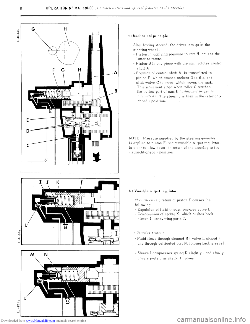
Downloaded from www.Manualslib.com manuals search engine a ) Mechanical principle
After having steered the driver lets go of the
s teerinq wheel
Piston F applyinq pressure to cam H, causes the
latter to rotate.
- Pinion B in one piece with the cam rotates control
shaft A.
- Rotation of control shaft A, is transmitted to
pinion E which causes rockers D to tilt and
slidecvalve C to move which moves the rack.
This movement stops when roller G reaches
the hollow part of cam H ( ro/~/i<,//~/ /or(//((’ is
(-(II/( V/I< N’ ) The steerinq is then in the c
NOTE Pressure supplied by the steering governor
is applied to piston F via a variable output requlator
in order to slow down the return of the steerinq to the
v straiqht-ahead a) position.
b)
Variable output regulator :
Wh(‘I/ \I< criq .’ return of piston F causes the
following
_ Expulsion of fluid through one-way valve L
= Compression of sprinq K. which pushes back
sleeve I uncovering ports J.
(1 . I vl,riil,q rc l//rI/ D
- Fluid flows throuqh channel M ( valve L closed )
and through calibrated port N, forcing back sleeve I.
= Sleeve I compresses sprinq K sliqhtly and slowly
covers ports J as piston F moves.
Page 270 of 394
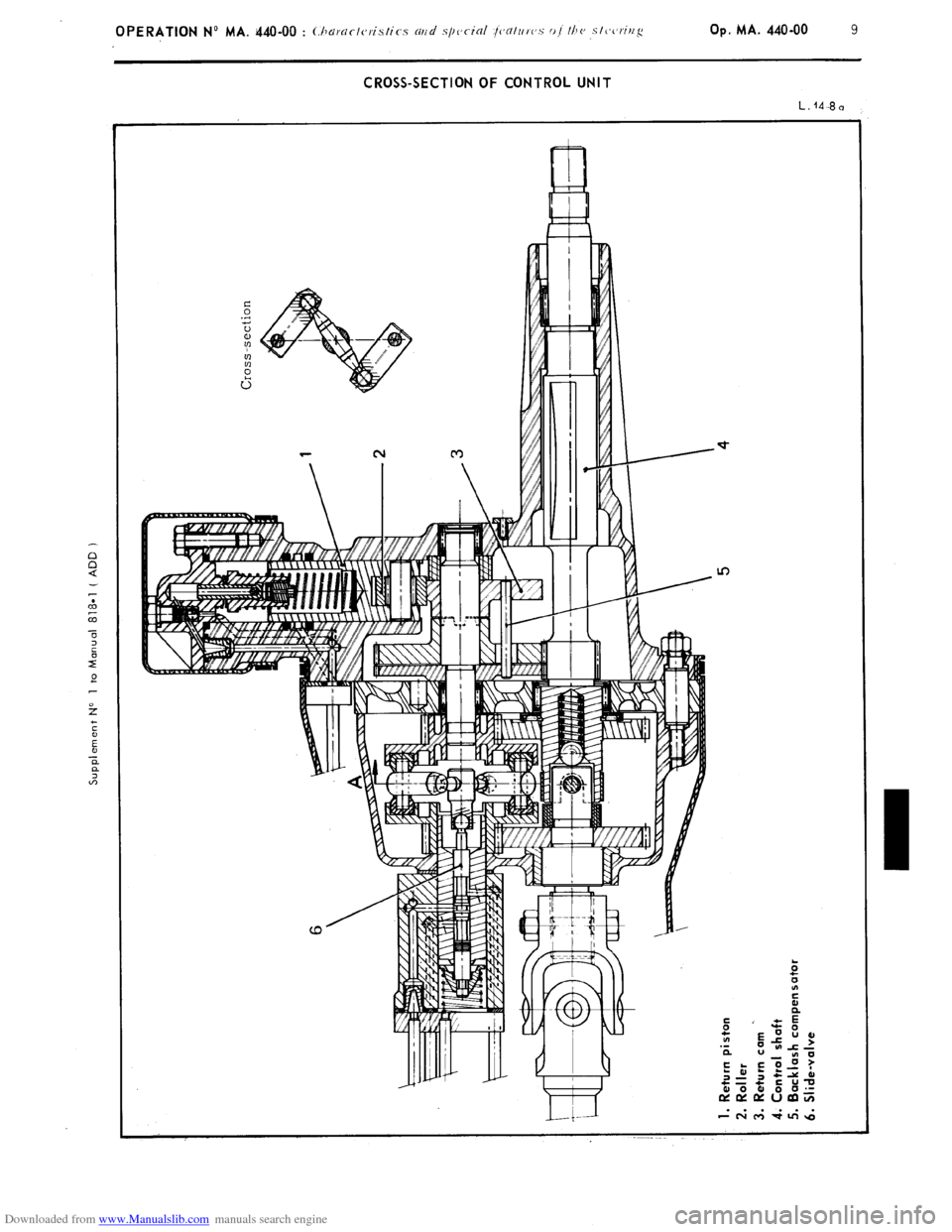
Downloaded from www.Manualslib.com manuals search engine CROSS-SECTION OF CONTROL UNIT
L. 14-3 n
In