Citroen DS3 2014 1.G Owner's Manual
Manufacturer: CITROEN, Model Year: 2014, Model line: DS3, Model: Citroen DS3 2014 1.GPages: 376, PDF Size: 12.55 MB
Page 221 of 376
219
DS3_en_Chap10_info-pratiques_ed01-2014
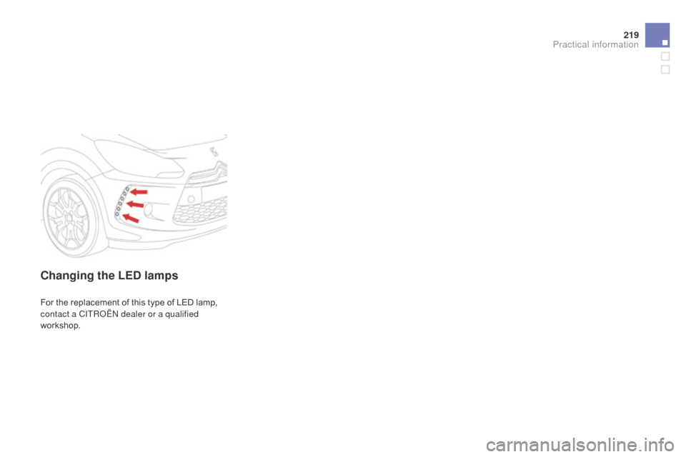
changing the LEd lamps
For the replacement of this type of LED lamp, c
ontact a CITRoË N dealer or a qualified
workshop.
Practical information
Page 222 of 376
DS3_en_Chap10_info-pratiques_ed01-2014
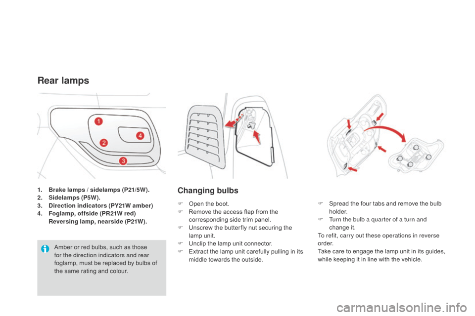
1. Brake lamps / sidelamps (P21/5W).
2. Sidelamps (P5W).
3.
di
rection indicators (PY21W amber)
4.
F
oglamp, offside (PR21W red)
R
eversing lamp, nearside (P21W).
Rear lamps
Amber or red bulbs, such as those for the direction indicators and rear
foglamp,
must be replaced by bulbs of
t
he same rating and colour.
changing bulbs
F Open the boot.
F R emove the access flap from the
c
orresponding side trim panel.
F
U
nscrew the butter fly nut securing the
lam
p
u
nit.
F
U
nclip the lamp unit connector.
F
E
xtract the lamp unit carefully pulling in its
m
iddle towards the outside. F
S pread the four tabs and remove the bulb h
o l d e r.
F
T
urn the bulb a quarter of a turn and
change
it
.
To refit, carry out these operations in reverse
o r d e r.
Take
care to engage the lamp unit in its guides,
w
hile keeping it in line with the vehicle.
Page 223 of 376
221
DS3_en_Chap10_info-pratiques_ed01-2014
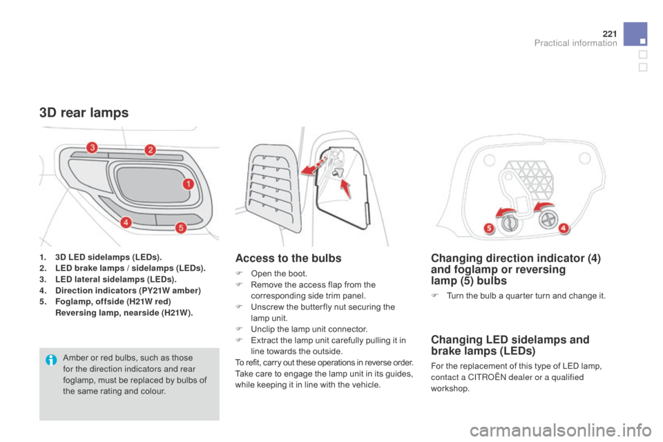
changing direction indicator (4)
and foglamp or reversing
lamp
(5) bulbs
F Turn the bulb a quarter turn and change it.
changing LEd sidelamps and
brake lamps (LEds )
For the replacement of this type of LED lamp, c
ontact a CITRoË N dealer or a qualified
workshop.
3d rear lamps
Access to the bulbs
F Open the boot.
F R emove the access flap from the
c
orresponding side trim panel.
F
U
nscrew the butter fly nut securing the
lam
p
u
nit.
F
U
nclip the lamp unit connector.
F
E
xtract the lamp unit carefully pulling it in
l
ine towards the outside.
To
refit, carry out these operations in reverse order.
Take
care to engage the lamp unit in its guides,
w
hile keeping it in line with the vehicle.
1.
3
d
L
E
d
s
idelamps (LE
d
s).
2. L
Ed
brake lamps / sidelamps (LEds
).
3. L
E
d la
teral sidelamps (LE
d
s).
4.
di
rection indicators (PY21W amber)
5.
F
oglamp, offside (H21W red)
R
eversing lamp, nearside (H21W).
Amber
or
red
bulbs,
such
as
those
f
or the direction indicators and rear
foglamp,
must
be
replaced
by
bulbs
of
t
he
same
rating
and
colour.
Practical information
Page 224 of 376
DS3_en_Chap10_info-pratiques_ed01-2014
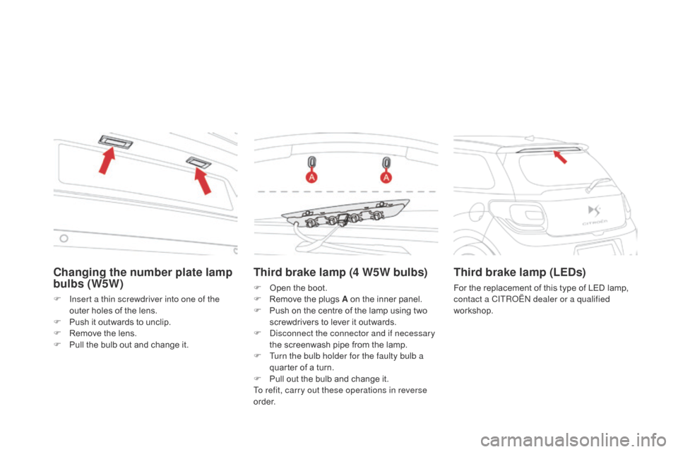
Third brake lamp (4 W5W bulbs)
F Open the boot.
F R emove the plugs A on the inner panel.
F
P
ush on the centre of the lamp using two
s
crewdrivers to lever it outwards.
F
D
isconnect the connector and if necessary
the
screenwash pipe from the lamp.
F
T
urn the bulb holder for the faulty bulb a
quarter
of a turn.
F
P
ull out the bulb and change it.
To refit, carry out these operations in reverse
o r d e r.
Third brake lamp (LEds )
For the replacement of this type of LED lamp, c
ontact a CITRoË N dealer or a qualified
workshop.
changing the number plate lamp
bulbs (W5W)
F Insert a thin screwdriver into one of the outer holes of the lens.
F
P
ush it outwards to unclip.
F
R
emove the lens.
F
P
ull the bulb out and change it.
Page 225 of 376
223
DS3_en_Chap10_info-pratiques_ed01-2014
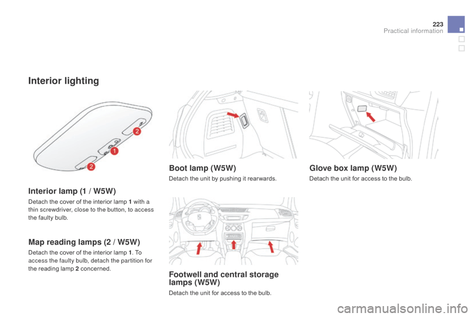
Interior lighting
Interior lamp (1 / W5W)
Detach the cover of the interior lamp 1 with a
t hin screwdriver, close to the button, to access
the
faulty bulb.
Map reading lamps (2 / W5W)
Detach the cover of the interior lamp 1. To a
ccess the faulty bulb, detach the partition for
the
reading lamp 2
c
oncerned.
Boot lamp (W5W)
Detach the unit by pushing it rear wards.
Footwell and central storage
lamps (W5W)
Detach the unit for access to the bulb.
Glove box lamp (W5W)
Detach the unit for access to the bulb.
Practical information
Page 226 of 376
DS3_en_Chap10_info-pratiques_ed01-2014
Changing a fuse
Installing electrical
accessories
Your vehicle's electrical system is designed to operate with standard or
o
ptional
e
quipment.
Before
installing other electrical
e
quipment or accessories on your
v
ehicle, contact a CITR
oË
N dealer or a
qualified
w
orkshop.
CITR
oË
N will not accept responsibility
for
the cost incurred in repairing your
v
ehicle or for rectifying malfunctions
r
esulting from the installation of
a
ccessories not supplied and not
recommended
by CITROËN and
n
ot installed in accordance with its
instructions, in particular when the
combined
consumption of all of the
a
dditional equipment connected
e
xceeds
1
0
mil
liamperes.
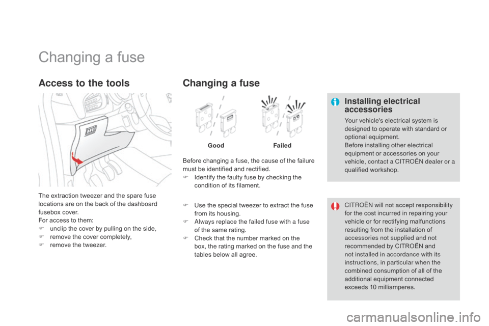
The
extraction
tweezer
and
the
spare
fuse
l
ocations
are
on
the
back
of
the
dashboard
f
usebox
cover.
For
access
to
them:
F
u
nclip
the
cover
by
pulling
on
the
side,
F
r
emove
the
cover
completely,
F
r
emove
the
tweezer.
Access to the tools
Before changing a fuse, the cause of the failure m ust be identified and rectified.
F
I
dentify the faulty fuse by checking the
c
ondition of its filament.
changing a fuse
Good Failed
F
U
se
the special tweezer to extract the fuse
f
rom
its housing.
F
a
l
ways replace the failed fuse with a fuse
of
the same rating.
F
C
heck that the number marked on the
b
ox,
the rating marked on the fuse and the
t
ables below all agree.
Page 227 of 376
225
DS3_en_Chap10_info-pratiques_ed01-2014
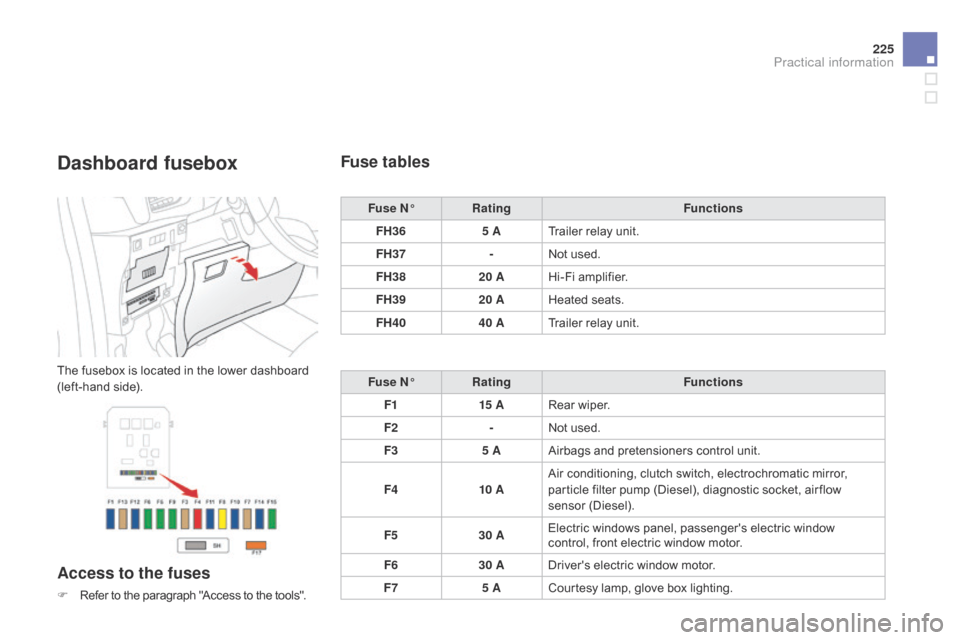
dashboard fusebox
The fusebox is located in the lower dashboard (left-hand side).
Access to the fuses
F Refer to the paragraph "Access to the tools".
Fuse tables
Fuse N°Rating Functions
FH36 5 ATrailer
relay unit.
FH37 -Not
used.
FH38 20 AHi-Fi
amplifier.
FH39 20 AHeated
s
eats.
FH40 40 ATrailer
relay unit.
Fuse N° Rating Functions
F1 15 ARear
wiper.
F2 -Not
used.
F3 5 AAirbags
and pretensioners control unit.
F4 10 AAir
conditioning, clutch switch, electrochromatic mirror,
p
article filter pump (Diesel), diagnostic socket, air flow
sen
sor
(
Diesel).
F5 30 AElectric
windows panel, passenger's electric window
c
ontrol, front electric window motor.
F6 30 ADriver's
electric window motor.
F7 5 ACourtesy
lamp, glove box lighting.
Practical information
Page 228 of 376
DS3_en_Chap10_info-pratiques_ed01-2014
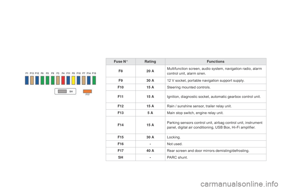
Fuse N°Rating Functions
F8 20 AMultifunction
screen, audio system, navigation radio, alarm
c
ontrol unit, alarm siren.
F9 30 A12
V socket, portable navigation support supply.
F10 15 ASteering
mounted controls.
F11 15 AIgnition,
diagnostic socket, automatic gearbox control unit.
F12 15 ARain
/ sunshine sensor, trailer relay unit.
F13 5 AMain
stop switch, engine relay unit.
F14 15 AParking
sensors control unit, airbag control unit, instrument
p
anel, digital air conditioning, USB Box, Hi-Fi amplifier.
F15 30 ALocking.
F16 -Not
used.
F17 40 ARear
screen and door mirrors demisting/defrosting.
SH -PARC
shunt.
Page 229 of 376
227
DS3_en_Chap10_info-pratiques_ed01-2014
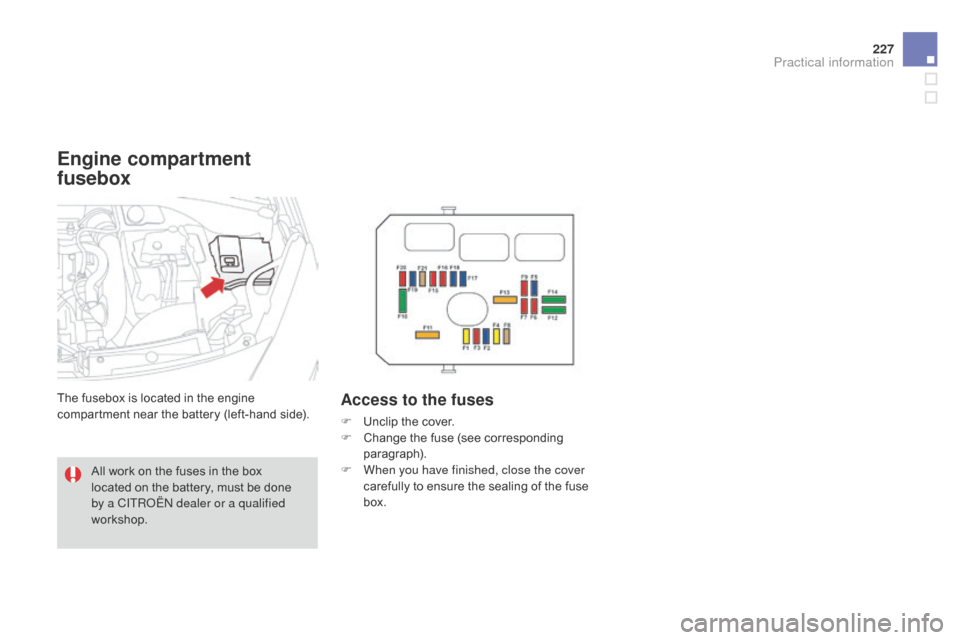
Engine compartment
fusebox
The fusebox is located in the engine compartment near the battery (left-hand side).Access to the fuses
F Unclip the cover.
F C hange the fuse (see corresponding
par
agraph).
F
W
hen you have finished, close the cover
carefully
to ensure the sealing of the fuse
b
ox.
All
work
on
the
fuses
in
the
box
l
ocated
on
the
battery,
must
be
done
b
y a CITR
oË
N dealer or a qualified
workshop.
Practical information
Page 230 of 376
DS3_en_Chap10_info-pratiques_ed01-2014
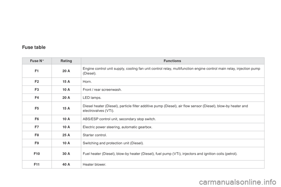
Fuse table
Fuse N°Rating Functions
F1 20 AEngine
control unit supply, cooling fan unit control relay, multifunction engine control main relay, injection pump
(
Diesel).
F2 15 AHorn.
F3 10 AFront
/ rear screenwash.
F4 20 ALED
lamps.
F5 15 ADiesel
heater (Diesel), particle filter additive pump (Diesel), air flow sensor (Diesel), blow-by heater and
e
lectrovalves (VTi).
F6 10 AABS/ESP
control unit, secondary stop switch.
F7 10 AElectric
power steering, automatic gearbox.
F8 25 AStarter
control.
F9 10 ASwitching
and protection unit (Diesel).
F10 30 AFuel
heater (Diesel), blow-by heater (Diesel), fuel pump (VTi), injectors and ignition coils (petrol).
F11 40 AHeater
b
lower.