fuse box CITROEN DS3 2018 Handbook (in English)
[x] Cancel search | Manufacturer: CITROEN, Model Year: 2018, Model line: DS3, Model: CITROEN DS3 2018Pages: 248, PDF Size: 8.79 MB
Page 5 of 248
3
07
08
0609
bit.ly/helpPSA
116 Driving recommendations
118
S
tarting-switching off the engine
120
P
arking brake
120
6
-speed manual gearbox
120
E
lectronic gearbox (ETG)
124
Aut
omatic gearbox
127
A
utomatic gearbox (EAT6)
130 Gear
ef ficiency indicator
131
H
ill start assist
132
St
op & Start
13 4 Tyre
under-inflation detection
136
Spe
ed limiter
138
C
ruise control
14 0
A
ctive City Brake
14 3
P
arking assistance
14 4
R
eversing camera 14 8 Fu
el tank
14 8
M
isfuel prevention (Diesel)
15 0
C
ompatibility of fuels
151
S
now chains
152
To w b a r
152
L
oad reduction mode
15 3
E
nergy economy mode
15 3
C
hanging wiper blades
15 3
Bonnet
15 4
Engines
155
Ch
ecking levels
157
C
hecks
15 9
Ad
Blue
® (BlueHDi engines)
162
A
dvice on care and maintenance
165
R
unning out of fuel (Diesel)
165
T
emporary puncture repair kit
169
S
pare wheel
174
C
hanging a
bulb
181
C
hanging a
fuse
188
1
2
V battery
191
To w i n g 194
C
haracteristics of engines and towed
loads
195
Pe
trol engines
198
D
iesel engines
199
Dimensions
201 Identification
ma
rkings
Driving
Practical information
In the event of a
breakdown Technical data
Alphabetical index Audio and telematics
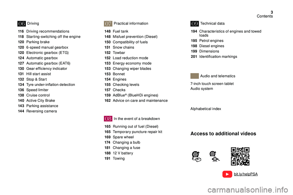
Access to additional videos
7-inch touch screen tablet
Audio system
Contents
Page 6 of 248
4
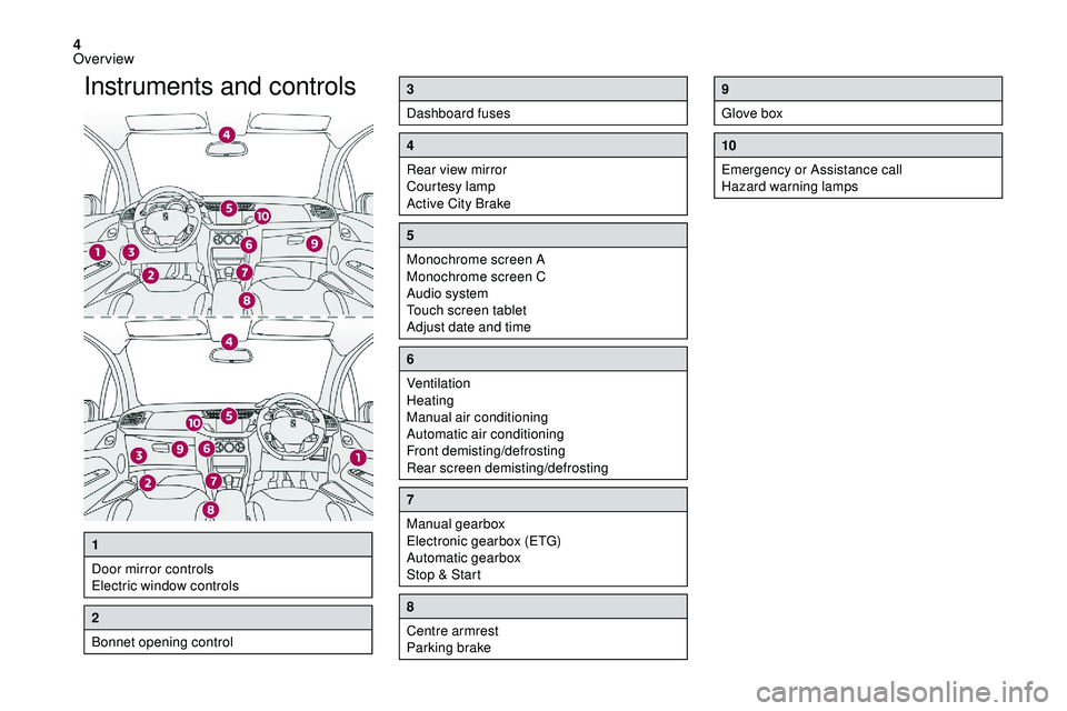
Instruments and controls3
Dashboard fuses
4
Rear view mirror
Courtesy lamp
Active City Brake
5
Monochrome screen A
Monochrome screen C
Audio system
Touch screen tablet
Adjust date and time
6
Ventilation
Heating
Manual air conditioning
Automatic air conditioning
Front demisting/defrosting
Rear screen demisting/defrosting
7
Manual gearbox
Electronic gearbox (ETG)
Automatic gearbox
Stop & Start
8
Centre armrest
Parking brake
9
Glove box
10
Emergency or Assistance call
Hazard warning lamps
1
Door mirror controls
Electric window controls
2
Bonnet opening control
Over view
Page 157 of 248
155
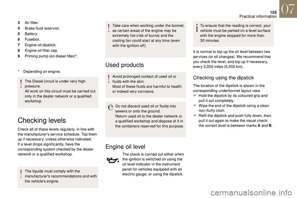
3A i r f i l t e r.
4 Brake fluid reser voir.
5 Battery.
6 Fusebox.
7 Engine oil dipstick.
8 Engine oil filler cap.
9 Priming pump (on diesel filter)*.
The Diesel circuit is under very high
pressure.
All work on this circuit must be carried out
only in the dealer network or a
qualified
workshop.
*
D
epending on engine.
Checking levels
Check all of these levels regularly, in line with
the manufacturer's service schedule. Top them
up if necessary, unless other wise indicated.
If a level drops significantly, have the
corresponding system checked by the dealer
network or a
qualified workshop.
The liquids must comply with the
manufacturer's recommendations and with
the vehicle's engine. Take care when working under the bonnet,
as certain areas of the engine may be
extremely hot (risk of burns) and the
cooling fan could start at any time (even
with the ignition off).
Used products
Avoid prolonged contact of used oil or
fluids with the skin.
Most of these fluids are harmful to health
or indeed very corrosive.
Do not discard used oil or fluids into
sewers or onto the ground.
Return used oil to the dealer network or
a
qualified workshop and dispose of it in
the containers reser ved for this purpose.
Engine oil level
The check is carried out either when
the ignition is switched on using the
oil level indicator in the instrument
panel for vehicles equipped with an
electric gauge, or using the dipstick. To ensure that the reading is correct, your
vehicle must be parked on a
level sur face
with the engine stopped for more than
30
minutes.
It is normal to top up the oil level between two
ser vices (or oil changes). We recommend that
you check the level, and top up if necessary,
every 3,000 miles (5,000 km).
Checking using the dipstick
The location of the dipstick is shown in the
corresponding underbonnet layout view.
F
H
old the dipstick by its coloured grip and
pull it out completely.
F
W
ipe the end of the dipstick using a clean
non-fluffy cloth.
F
R
efit the dipstick and push fully down, then
pull it out again to make the visual check:
the correct level is between marks A and B .
07
Practical information
Page 183 of 248
181
Changing a fuse
Access to the tools
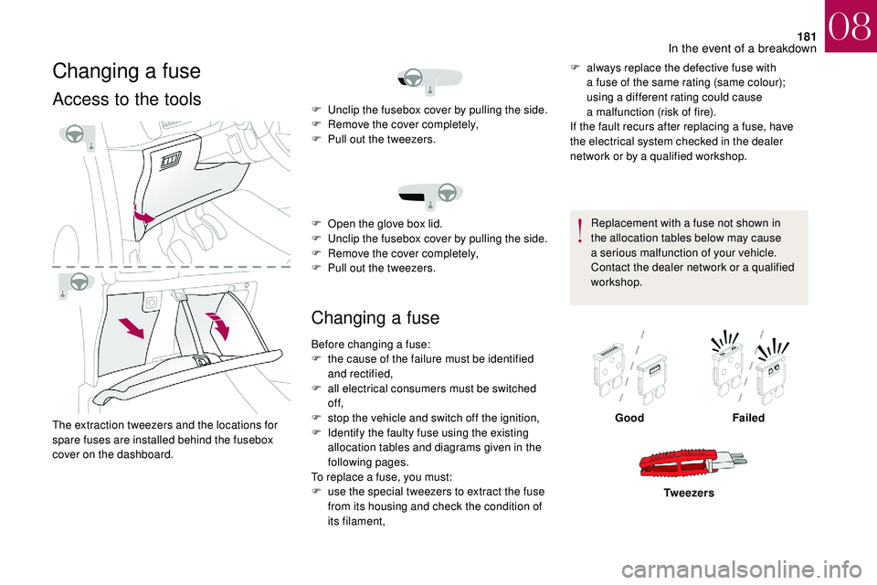
The extraction tweezers and the locations for
spare fuses are installed behind the fusebox
cover on the dashboard.
Changing a fuse
F always replace the defective fuse with
a fuse of the same rating (same colour);
using a
different rating could cause
a
malfunction (risk of fire).
If the fault recurs after replacing a
fuse, have
the electrical system checked in the dealer
network or by a
qualified workshop.
Replacement with a
fuse not shown in
the allocation tables below may cause
a
serious malfunction of your vehicle.
Contact the dealer network or a
qualified
workshop.
F
U
nclip the fusebox cover by pulling the side.
F
R
emove the cover completely,
F
P
ull out the tweezers.
F
O
pen the glove box lid.
F
U
nclip the fusebox cover by pulling the side.
F
R
emove the cover completely,
F
P
ull out the tweezers.
Before changing a
fuse:
F
t
he cause of the failure must be identified
and rectified,
F
a
ll electrical consumers must be switched
of f,
F
s
top the vehicle and switch off the ignition,
F
I
dentify the faulty fuse using the existing
allocation tables and diagrams given in the
following pages.
To replace a
fuse, you must:
F
u
se the special tweezers to extract the fuse
from its housing and check the condition of
its filament, Good
Failed
Tw e e z e r s
08
In the event of a breakdown
Page 184 of 248
182
Installing electrical accessories
Your vehicle's electrical system is designed
to operate with standard or optional
equipment.
Before installing other electrical equipment
or accessories on your vehicle, contact the
dealer network or a qualified workshop.
DS AUTOMOBILES accepts no
responsibility for the cost incurred in
repairing your vehicle or for rectifying
malfunctions resulting from the installation of
accessories not supplied, not recommended
and not installed in accordance with its
specifications, in particular when the
combined power consumption of all of the
additional equipment connected exceeds
10
milliamperes.Fuses in the dashboard
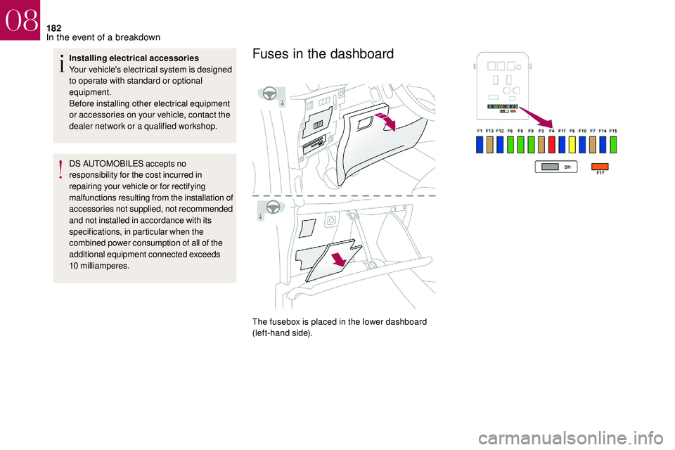
The fusebox is placed in the lower dashboard
(left-hand side).
08
In the event of a breakdown
Page 185 of 248
183
Table of fuses
Fuse no.Rating Functions
FH36 5
ATrailer inter face unit.
FH37 -Not used.
FH38 20
AHi-Fi amplifier.
FH39 20
AHeated seats.
FH40 40
ATrailer inter face unit.
Fuse no. Rating Functions
F1 15
ARear wiper.
F2 -Not used.
F3 5
AAirbags and pyrotechnic pretensioners control unit.
F4 10
AAir conditioning, clutch pedal switch, electrochrome mirror, Diesel particle filter pump, diagnostic socket, air flow
meter (Diesel).
F5 30
AElectric window panel, passenger electric window control, front electric window motor.
F6 30
ADriver's electric window motor.
F7 5
ACourtesy lamp, glove box lighting.
08
In the event of a breakdown
Page 186 of 248
184
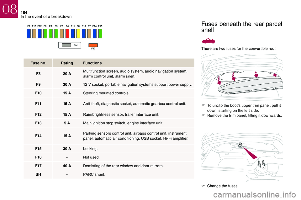
There are two fuses for the convertible roof.F
T
o unclip the boot's upper trim panel, pull it
down, starting on the left side.
F
R
emove the trim panel, tilting it downwards.
Fuse no.
Rating Functions
F8 20
A Multifunction screen, audio system, audio navigation system,
alarm control unit, alarm siren.
F9 30
A 12
V socket, portable navigation systems support power supply.
F10 15
A Steering mounted controls.
F11 15
A Anti-theft, diagnostic socket, automatic gearbox control unit.
F12 15
A Rain/brightness sensor, trailer interface unit.
F13 5
A Main ignition stop switch, engine interface unit.
F14 15
A Parking sensors control unit, airbags control unit, instrument
panel, automatic air conditioning, USB socket, Hi-Fi amplifier.
F15 30
A Locking.
F16 -Not used.
F17 40
A Demisting of the rear window and door mirrors.
SH -PARC shunt.
Fuses beneath the rear parcel
shelf
F Change the fuses.
08
In the event of a breakdown
Page 187 of 248

185
For reassembly, carry out these operations
in reverse order, starting at the bottom of the
boot.Fuse No. Rating Functions
- 20
AConvertible roof.
- 20
AConvertible roof.
If the roof is in zone B when the fuses fail,
opening the boot is not possible. To be
able to open the boot and then replace the
fuses, first close the roof manually from
inside the boot (by folding the rear bench
seat).Fuses in the engine
compartment
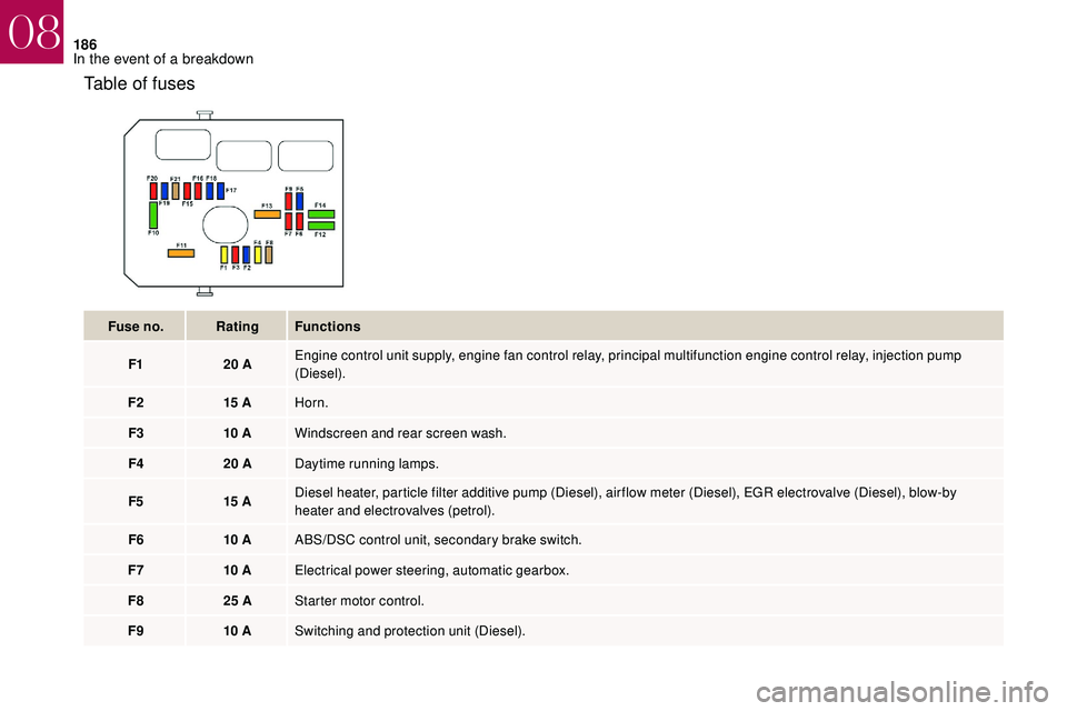
The fusebox is located in the engine
compartment near the battery (left-hand side).
Any work on the fuses of the unit, located
on the battery, must be carried out only
in the dealer network or by a
qualified
workshop.
Access to the fuses
F Unclip the cover
F C hange the fuse.
F
W
hen you have finished, close the cover
very carefully to ensure correct sealing of
the fuse box.
08
In the event of a breakdown
Page 188 of 248
186
Table of fuses
Fuse no.Rating Functions
F1 20
AEngine control unit supply, engine fan control relay, principal multifunction engine control relay, injection pump
(Diesel).
F2 15
AHorn.
F3 10
AWindscreen and rear screen wash.
F4 20
ADaytime running lamps.
F5 15
ADiesel heater, particle filter additive pump (Diesel), air flow meter (Diesel), EGR electrovalve (Diesel), blow-by
heater and electrovalves (petrol).
F6 10
AABS/DSC control unit, secondary brake switch.
F7 10
AElectrical power steering, automatic gearbox.
F8 25
AStarter motor control.
F9 10
ASwitching and protection unit (Diesel).
08
In the event of a breakdown
Page 190 of 248
188
12 V battery
Procedure for starting the engine using another
battery or charging a
discharged battery.
General points
Lead-acid starter batteries
Batteries contain harmful substances
such as sulphuric acid and lead.
They must be disposed of in accordance
with regulations and must not, in any
circumstances, be discarded with
household waste.
Take used remote control batteries and
vehicle batteries to a
special collection
point.
Protect your eyes and face before
handling the battery.
All operations on the battery must be
carried out in a
well ventilated area and
away from naked flames and sources of
sparks, so as to avoid the risk of explosion
or fire.
Wash your hands afterwards.
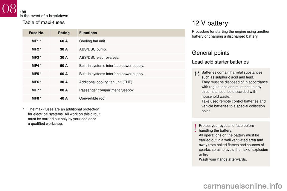
Table of maxi-fuses
Fuse No. Rating Functions
MF1
* 60
ACooling fan unit.
MF2
* 30
AABS/DSC pump.
MF3
* 30
AABS/DSC electrovalves.
MF4
* 60
ABuilt-in systems inter face power supply.
MF5
* 60
ABuilt-in systems inter face power supply.
MF6
* 30
AAdditional cooling fan unit (THP).
MF7
* 80
APassenger compartment fusebox.
MF8
* 40
AConvertible roof.
*
T
he maxi-fuses are an additional protection
for electrical systems. All work on this circuit
must be carried out only by your dealer or
a
qualified workshop.
08
In the event of a breakdown