CITROEN DS3 CABRIO 2016 Handbook (in English)
Manufacturer: CITROEN, Model Year: 2016, Model line: DS3 CABRIO, Model: CITROEN DS3 CABRIO 2016Pages: 450, PDF Size: 17.47 MB
Page 221 of 450

219
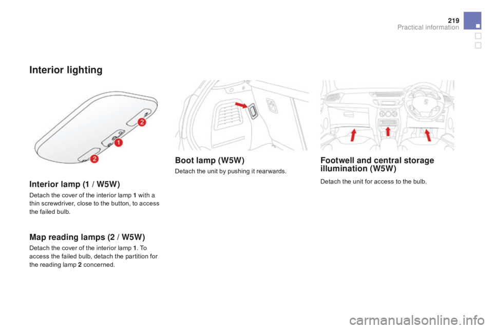
Interior lighting
Interior lamp (1 / W5W)
Detach the cover of the interior lamp 1 with a
t hin screwdriver, close to the button, to access
t
he failed bulb.
Map reading lamps (2 / W5W)
Detach the cover of the interior lamp 1. To a
ccess the failed bulb, detach the partition for
t
he reading lamp 2
c
oncerned.
Boot lamp (W5W)
Detach the unit by pushing it rear wards.
Footwell and central storage
illumination (W5W)
Detach the unit for access to the bulb.
Practical information
Page 222 of 450

Changing a fuse
Installing electrical
accessories
Your vehicle's electrical system is designed to operate with standard or
o
ptional
e
quipment.
Before
installing other electrical
e
quipment or accessories on your
v
ehicle, contact a CITROËN dealer or a
q
ualified
w
orkshop.
CITROËN will not accept responsibility
for
the cost incurred in repairing your
v
ehicle or for rectifying malfunctions
r
esulting from the installation of
a
ccessories not supplied and not
r
ecommended by CITROËN and
n
ot installed in accordance with its
in
structions, in particular when the
combined
consumption of all of the
a
dditional equipment connected
e
xceeds
1
0
mil
liamperes.
The
extraction
tweezer
and
the
spare
fuse
s
torage
locations
are
on
the
back
of
the
d
ashboard
fuse
box
cover.
For
access
to
them:
F
o
pen
the
glove
box
lid,
F
u
nclip
the
fusebox
cover
by
pulling
on
the
si
de,
F
r
emove
the
cover
completely,
F
r
emove
the
tweezer.
Access to the tools
Before changing a fuse, the cause of the failure m ust be identified and rectified.
F
I
dentify the faulty fuse by checking the
c
ondition of its filament.
Changing a fuse
good Failed
F
U
se
the special tweezer to extract the fuse
f
rom
its housing.
F
A
lways replace the faulty fuse with a fuse
of
the same rating.
F
C
heck that the number marked on the
b
ox,
the rating marked on the fuse and the
t
ables below all agree.
Page 223 of 450

221
dashboard fusebox
The fusebox is loacted inside the glove box.
Access to the fuses
F Refer to the paragraph "Access to the t
o o ls".
Fuse tables
Fuse n° R ating Functions
FH36 5 ATrailer
relay unit.
FH37 -Not
used.
FH38 20 AHi-Fi
amplifier.
FH39 -Not
used.
FH40 40 ATrailer
relay unit.
Fuse
n
° R
ating Functions
F1 15 ARear
wiper.
F2 -Not
used.
F3 5 AAirbags
and pretensioners control unit.
F4 10 AAir
conditioning, clutch switch, electrochromatic mirror,
p
article filter pump (Diesel), diagnostic socket, air flow
sen
sor
(
Diesel).
F5 30 AElectric
windows panel, passenger's electric window
c
ontrol, front electric window motor.
F6 30 ADriver's
electric window motor.
F7 5 ACourtesy
lamp.
Practical information
Page 224 of 450

Fuse n°R ating Functions
F8 20 AMultifunction
screen, audio system, navigation radio, alarm
c
ontrol unit, alarm siren.
F9 30 A12
V socket, portable navigation support supply.
F10 15 ASteering
wheel controls.
F11 15 AIgnition,
diagnostic socket, automatic gearbox control unit.
F12 15 ARain
/ brightness sensor, trailer relay unit.
F13 5 AMain
stop switch, engine relay unit.
F14 15 AParking
sensors control unit, airbag control unit, instrument
p
anel, digital air conditioning, USB Box, Hi-Fi amplifier.
F15 30 ALocking.
F16 -Not
used.
F17 40 ARear
screen and door mirrors demisting/defrosting.
SH -PARC
shunt.
Page 225 of 450

223
Engine compartment
fusebox
The fusebox is placed in the engine compartment near the battery (left-hand side).Access to the fuses
F Unclip the cover.
F C hange the fuse (see corresponding
par
agraph).
F
W
hen you have finished, close the cover
c
arefully to ensure the sealing of the
f
usebox.
All
work
on
the
fuses
in
this
box,
l
ocated
on
the
battery,
must
be
carried
o
ut
by
a
CITROËN
dealer
or
a
qualified
w
orkshop.
Practical information
Page 226 of 450

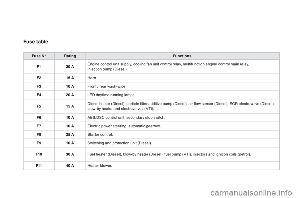
Fuse table
Fuse n°R ating Functions
F1 20 AEngine
control unit supply, cooling fan unit control relay, multifunction engine control main relay,
injection
pump (Diesel).
F2 15 AHorn.
F3 10 AFront
/ rear wash-wipe.
F4 20 ALED
daytime running lamps.
F5 15 ADiesel
heater (Diesel), particle filter additive pump (Diesel), air flow sensor (Diesel), EGR electrovalve (Diesel),
b
low-by heater and electrovalves (VTi).
F6 10 AABS/DSC
control unit, secondary stop switch.
F7 10 AElectric
power steering, automatic gearbox.
F8 25 AStarter
control.
F9 10 ASwitching
and protection unit (Diesel).
F10 30 AFuel
heater (Diesel), blow-by heater (Diesel), fuel pump (VTi), injectors and ignition coils (petrol).
F11 40 AHeater
b
lower.
Page 227 of 450

225
Fuse n°R ating Functions
F12 30 AWindscreen
wipers slow / fast speed.
F13 40 ABuilt-in
systems inter face supply (ignition positive).
F14 30 AValvetronic
supply (VTi).
F15 10 ARight-hand
main beam headlamps.
F16 10 ALeft-hand
main beam headlamps.
F17 15 ALeft-hand
dipped beam headlamps.
F18 15 ARight-hand
dipped beam headlamps.
F19 15 AOxygen
sensors and electrovalves (VTi), electrovalves
(
Diesel), EGR electrovalve (Diesel).
F20 10 APumps,
electronic thermostat (VTi), timimg electrovalve
(
THP), water in fuel sensor (Diesel).
F21 5 AFan
assembly control supply, ABS/DSC, turbo pump (THP).
Practical information
Page 228 of 450

Table of maxi-fuses
Fuse n°R ating Functions
MF1* 60 AFan
assembly.
MF2* 30 AABS
/ DSC pump.
MF3* 30 AABS
/ DSC electrovalves.
MF4* 60 ABuilt-in
Systems Inter face (BSI) supply.
MF5* 60 ABuilt-in
Systems Inter face (BSI) supply.
MF6* 30 AAdditional
cooling fan unit (THP).
MF7* 80 ADashboard
f
usebox.
MF8* -Not
used.
*
T
he maxi-fuses provide additional protection for the electrical systems. All work on the maxi-fuses must be carried out by a CITROËN dealer or
a q
ualified workshop.
Page 229 of 450

227
BatteryProcedure for charging your battery when it is flat or for starting the engine using another battery.T he battery is located under the bonnet.
To
gain access to it:
F
o
pen the bonnet using the interior release
l
ever, then the exterior safety catch,
F
s
ecure the bonnet stay,
F
l
ift the plastic cover on the (+) terminal.
Access to the batteryAfter refitting the battery by a CITROËN dealer or a qualified
w
orkshop, the Stop & Start system
w
ill only be active after a continuous
period
of immobilisation of the vehicle,
a
period which depends on the climatic
c
onditions and the state of charge of
t
he battery (up to about 8 hours).
The presence of this label, in particular
with
the
Stop
&
Start
system,
indicates
t
he
use
of
a
12
V
lead-acid
battery
with
s
pecial
t
echnology
a
nd
s
pecification;
t
he
involvement
of
a
CITROËN
dealer
o
r
a
qualified
workshop
is
essential
w
hen
replacing
or
disconnecting
the
b
attery.
Failure
t
o
o
bserve
t
his
r
ecommendation
m
ay
cause
premature
wear
of
the
b
attery.
Practical information
Page 230 of 450

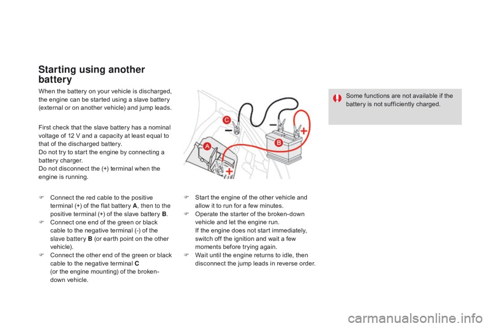
When the battery on your vehicle is discharged, the engine can be started using a slave battery
(
external or on another vehicle) and jump leads.
Starting using another
battery
First check that the slave battery has a nominal voltage of 12 V and a capacity at least equal to
t
hat of the discharged battery.
Do
not try to start the engine by connecting a
b
attery charger.
Do
not disconnect the (+) terminal when the
e
ngine is running.
F
C
onnect the red cable to the positive
t
erminal (+) of the flat battery A, then to the
positive
terminal (+) of the slave battery B.
F
C
onnect one end of the green or black
c
able to the negative terminal (-) of the
s
lave battery B (or earth point on the other
v
ehicle).
F
C
onnect
t
he
o
ther
e
nd
o
f
t
he
g
reen
o
r
b
lack
c
able to the negative terminal C
(or
the engine mounting) of the broken-
down
vehicle. F
S
tart the engine of the other vehicle and
a
llow it to run for a few minutes.
F
O
perate the starter of the broken-down
v
ehicle and let the engine run.
I
f the engine does not start immediately,
s
witch off the ignition and wait a few
m
oments before trying again.
F
W
ait until the engine returns to idle, then
d
isconnect the jump leads in reverse order.Some
functions are not available if the
b
attery is not sufficiently charged.