DAEWOO LACETTI 2004 Service Repair Manual
Manufacturer: DAEWOO, Model Year: 2004, Model line: LACETTI, Model: DAEWOO LACETTI 2004Pages: 2643, PDF Size: 80.54 MB
Page 2261 of 2643

LIGHTING SYSTEMS 9B – 35
DAEWOO V–121 BL4
StepNo Yes Value(s) Action
12Repair the open circuit between the fog lamp relay
terminal 87 and the fog lamps.
Is the repair complete?–System OK–
13Use an ohmmeter (or test lamp) to check the ground
at terminal 1 of the fog lamp connector.
Does the resistance equal the specified value?0 WGo to Step 15Go to Step 14
14Repair the fog lamp ground circuit.
Is the repair complete?–System OK–
15Replace the faulty fog lamp bulbs.
Is the repair complete?–System OK–
Page 2262 of 2643
9B – 36ILITHING SYSTEMS
DAEWOO V–121 BL4
MAINTENANCE AND REPAIR
ON–VEHICLE SERVICE
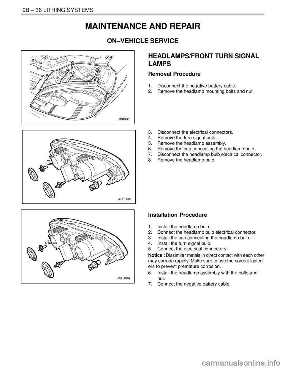
HEADLAMPS/FRONT TURN SIGNAL
LAMPS
Removal Procedure
1. Disconnect the negative battery cable.
2. Remove the headlamp mounting bolts and nut.
3. Disconnect the electrical connectors.
4. Remove the turn signal bulb.
5. Remove the headlamp assembly.
6. Remove the cap concealing the headlamp bulb.
7. Disconnect the headlamp bulb electrical connector.
8. Remove the headlamp bulb.
Installation Procedure
1. Install the headlamp bulb.
2. Connect the headlamp bulb electrical connector.
3. Install the cap concealing the headlamp bulb.
4. Install the turn signal bulb.
5. Connect the electrical connectors.
Notice : Dissimilar metals in direct contact with each other
may corrode rapidly. Make sure to use the correct fasten-
ers to prevent premature corrosion.
6. Install the headlamp assembly with the bolts and
nut.
7. Connect the negative battery cable.
Page 2263 of 2643
LITHING SYSTEMS 9B – 37
DAEWOO V–121 BL4
Tighten
Tighten the headlamp assembly bolts and nut to 4
NSm (35 lb–in).
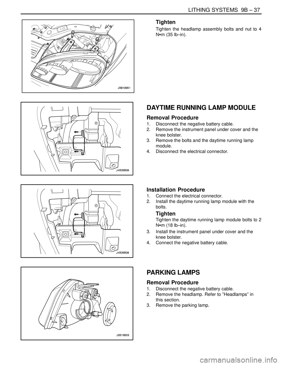
DAYTIME RUNNING LAMP MODULE
Removal Procedure
1. Disconnect the negative battery cable.
2. Remove the instrument panel under cover and the
knee bolster.
3. Remove the bolts and the daytime running lamp
module.
4. Disconnect the electrical connector.
Installation Procedure
1. Connect the electrical connector.
2. Install the daytime running lamp module with the
bolts.
Tighten
Tighten the daytime running lamp module bolts to 2
NSm (18 lb–in).
3. Install the instrument panel under cover and the
knee bolster.
4. Connect the negative battery cable.
PARKING LAMPS
Removal Procedure
1. Disconnect the negative battery cable.
2. Remove the headlamp. Refer to ”Headlamps” in
this section.
3. Remove the parking lamp.
Page 2264 of 2643
9B – 38ILITHING SYSTEMS
DAEWOO V–121 BL4
Installation Procedure
1. Install the parking lamp.
2. Install the headlamp. Refer to ”Headlamps” in this
section.
3. Connect the negative battery cable.
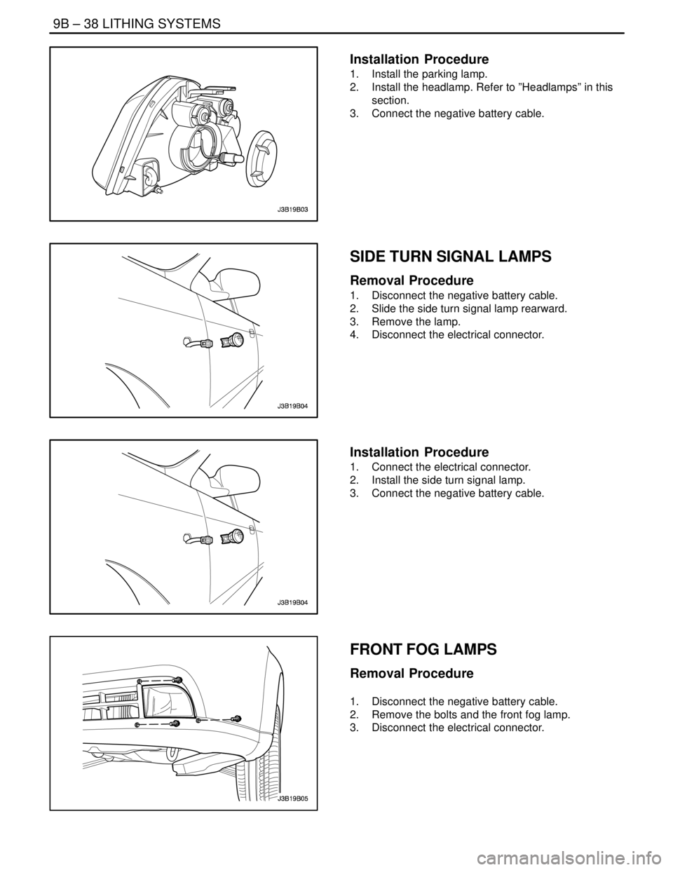
SIDE TURN SIGNAL LAMPS
Removal Procedure
1. Disconnect the negative battery cable.
2. Slide the side turn signal lamp rearward.
3. Remove the lamp.
4. Disconnect the electrical connector.
Installation Procedure
1. Connect the electrical connector.
2. Install the side turn signal lamp.
3. Connect the negative battery cable.
FRONT FOG LAMPS
Removal Procedure
1. Disconnect the negative battery cable.
2. Remove the bolts and the front fog lamp.
3. Disconnect the electrical connector.
Page 2265 of 2643
LITHING SYSTEMS 9B – 39
DAEWOO V–121 BL4
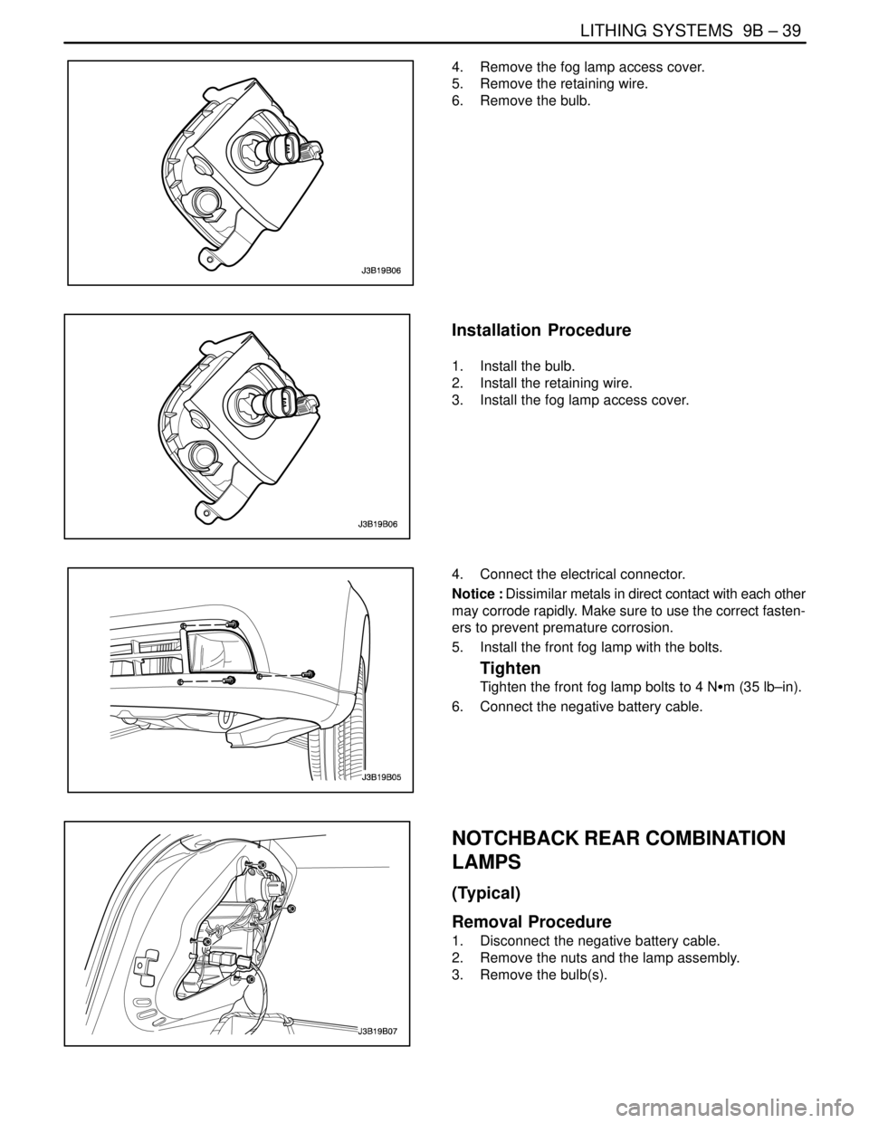
4. Remove the fog lamp access cover.
5. Remove the retaining wire.
6. Remove the bulb.
Installation Procedure
1. Install the bulb.
2. Install the retaining wire.
3. Install the fog lamp access cover.
4. Connect the electrical connector.
Notice : Dissimilar metals in direct contact with each other
may corrode rapidly. Make sure to use the correct fasten-
ers to prevent premature corrosion.
5. Install the front fog lamp with the bolts.
Tighten
Tighten the front fog lamp bolts to 4 NSm (35 lb–in).
6. Connect the negative battery cable.
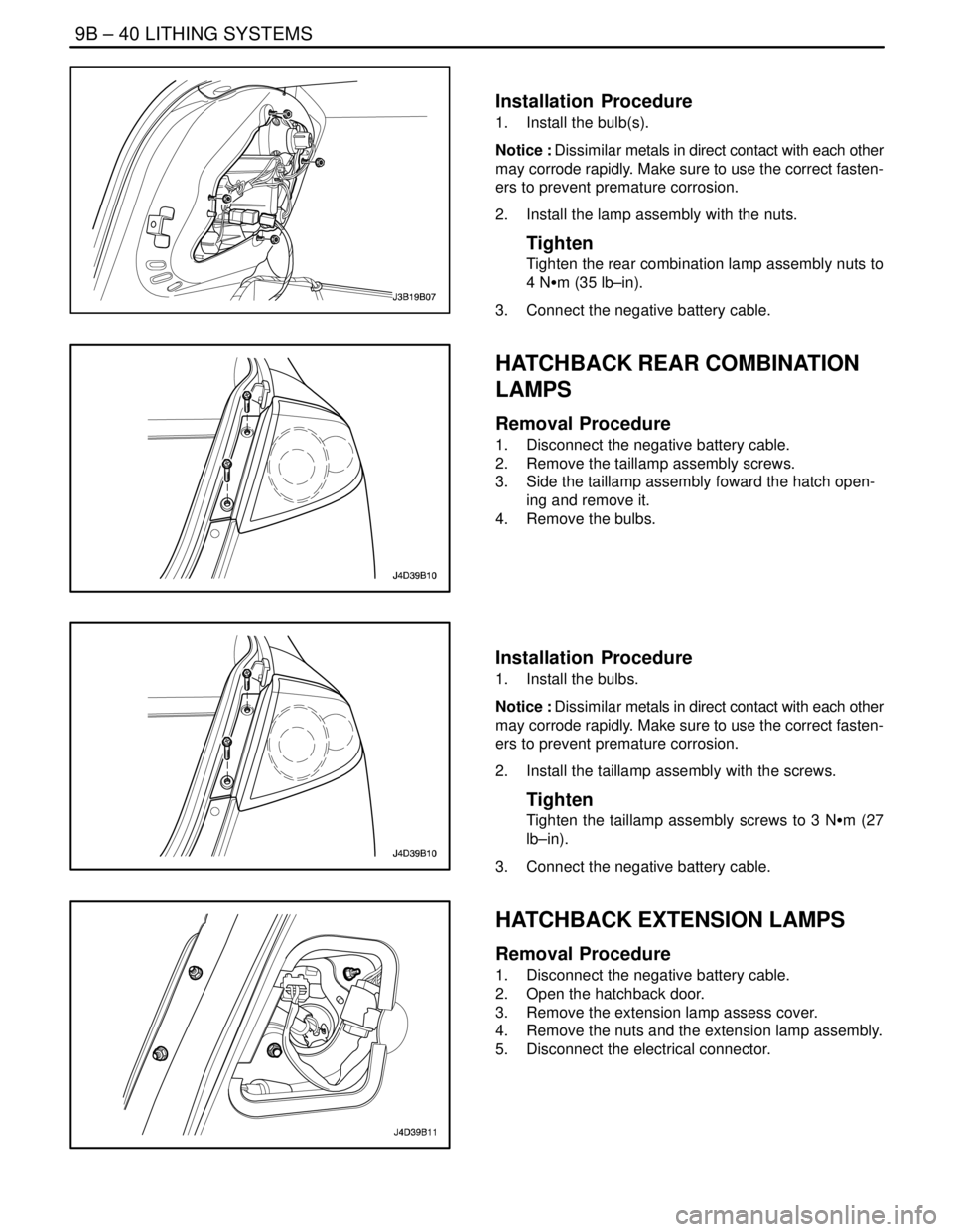
NOTCHBACK REAR COMBINATION
LAMPS
(Typical)
Removal Procedure
1. Disconnect the negative battery cable.
2. Remove the nuts and the lamp assembly.
3. Remove the bulb(s).
Page 2266 of 2643
9B – 40ILITHING SYSTEMS
DAEWOO V–121 BL4
Installation Procedure
1. Install the bulb(s).
Notice : Dissimilar metals in direct contact with each other
may corrode rapidly. Make sure to use the correct fasten-
ers to prevent premature corrosion.
2. Install the lamp assembly with the nuts.
Tighten
Tighten the rear combination lamp assembly nuts to
4 NSm (35 lb–in).
3. Connect the negative battery cable.
HATCHBACK REAR COMBINATION
LAMPS
Removal Procedure
1. Disconnect the negative battery cable.
2. Remove the taillamp assembly screws.
3. Side the taillamp assembly foward the hatch open-
ing and remove it.
4. Remove the bulbs.
Installation Procedure
1. Install the bulbs.
Notice : Dissimilar metals in direct contact with each other
may corrode rapidly. Make sure to use the correct fasten-
ers to prevent premature corrosion.
2. Install the taillamp assembly with the screws.
Tighten
Tighten the taillamp assembly screws to 3 NSm (27
lb–in).
3. Connect the negative battery cable.
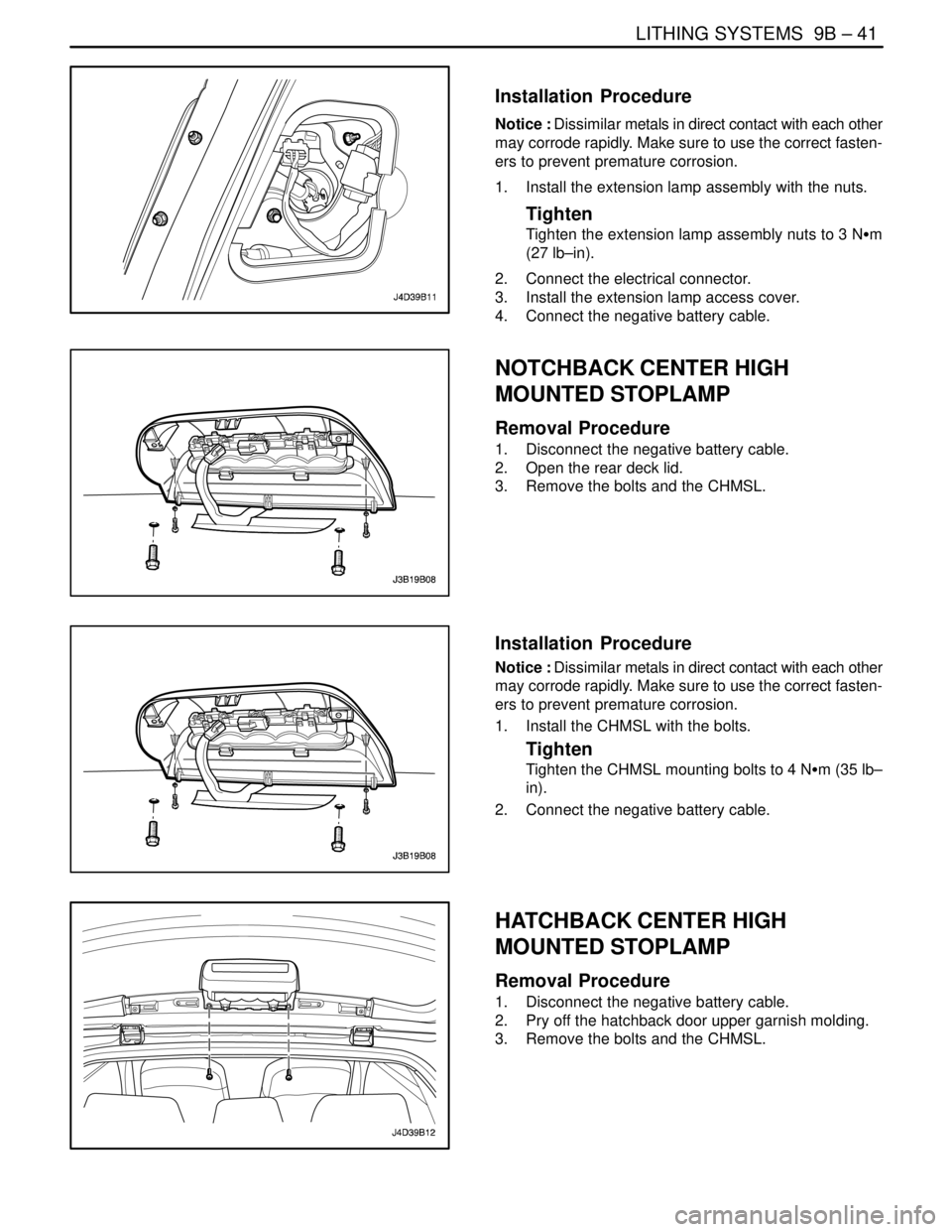
HATCHBACK EXTENSION LAMPS
Removal Procedure
1. Disconnect the negative battery cable.
2. Open the hatchback door.
3. Remove the extension lamp assess cover.
4. Remove the nuts and the extension lamp assembly.
5. Disconnect the electrical connector.
Page 2267 of 2643
LITHING SYSTEMS 9B – 41
DAEWOO V–121 BL4
Installation Procedure
Notice : Dissimilar metals in direct contact with each other
may corrode rapidly. Make sure to use the correct fasten-
ers to prevent premature corrosion.
1. Install the extension lamp assembly with the nuts.
Tighten
Tighten the extension lamp assembly nuts to 3 NSm
(27 lb–in).
2. Connect the electrical connector.
3. Install the extension lamp access cover.
4. Connect the negative battery cable.
NOTCHBACK CENTER HIGH
MOUNTED STOPLAMP
Removal Procedure
1. Disconnect the negative battery cable.
2. Open the rear deck lid.
3. Remove the bolts and the CHMSL.
Installation Procedure
Notice : Dissimilar metals in direct contact with each other
may corrode rapidly. Make sure to use the correct fasten-
ers to prevent premature corrosion.
1. Install the CHMSL with the bolts.
Tighten
Tighten the CHMSL mounting bolts to 4 NSm (35 lb–
in).
2. Connect the negative battery cable.
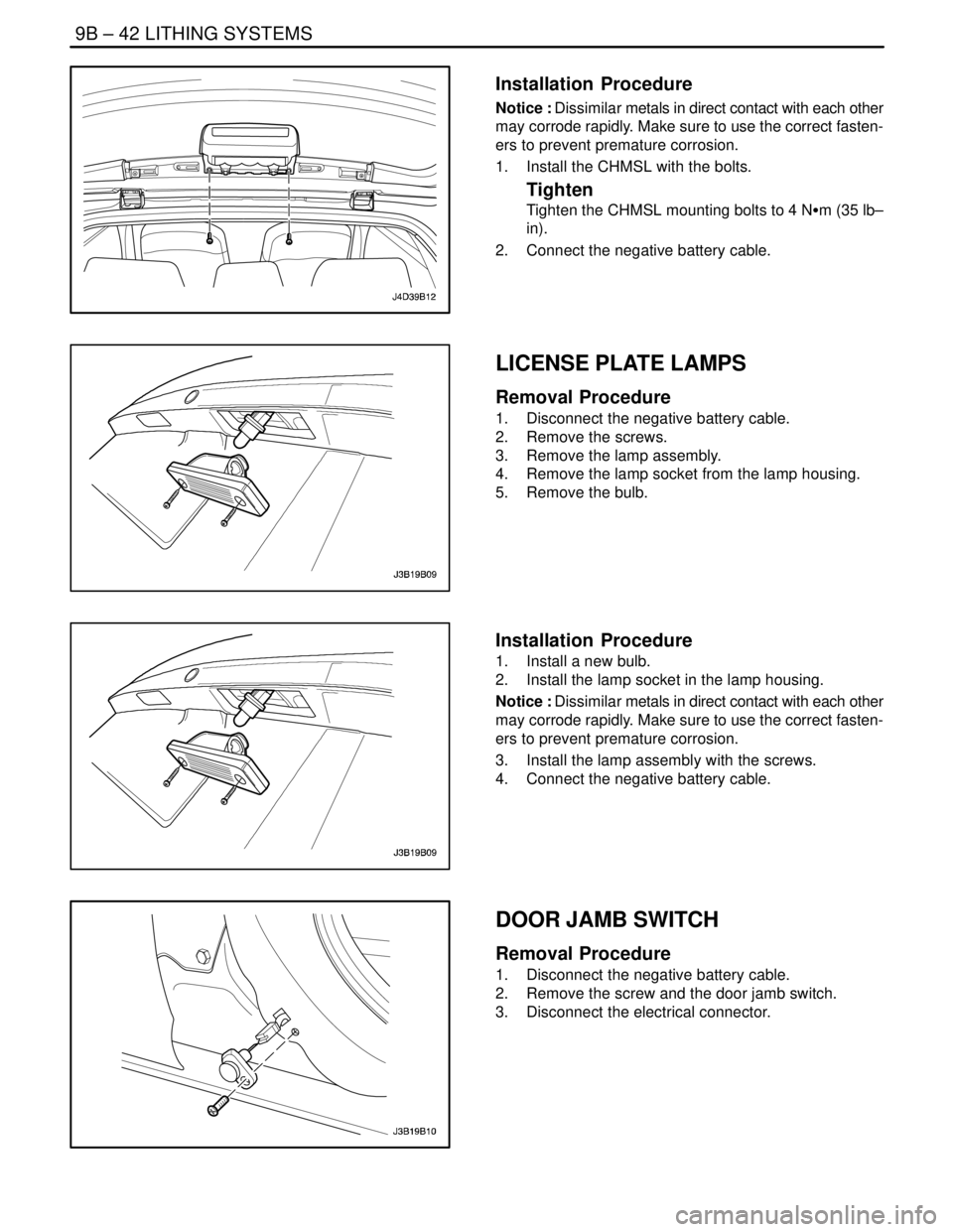
HATCHBACK CENTER HIGH
MOUNTED STOPLAMP
Removal Procedure
1. Disconnect the negative battery cable.
2. Pry off the hatchback door upper garnish molding.
3. Remove the bolts and the CHMSL.
Page 2268 of 2643
9B – 42ILITHING SYSTEMS
DAEWOO V–121 BL4
Installation Procedure
Notice : Dissimilar metals in direct contact with each other
may corrode rapidly. Make sure to use the correct fasten-
ers to prevent premature corrosion.
1. Install the CHMSL with the bolts.
Tighten
Tighten the CHMSL mounting bolts to 4 NSm (35 lb–
in).
2. Connect the negative battery cable.
LICENSE PLATE LAMPS
Removal Procedure
1. Disconnect the negative battery cable.
2. Remove the screws.
3. Remove the lamp assembly.
4. Remove the lamp socket from the lamp housing.
5. Remove the bulb.
Installation Procedure
1. Install a new bulb.
2. Install the lamp socket in the lamp housing.
Notice : Dissimilar metals in direct contact with each other
may corrode rapidly. Make sure to use the correct fasten-
ers to prevent premature corrosion.
3. Install the lamp assembly with the screws.
4. Connect the negative battery cable.
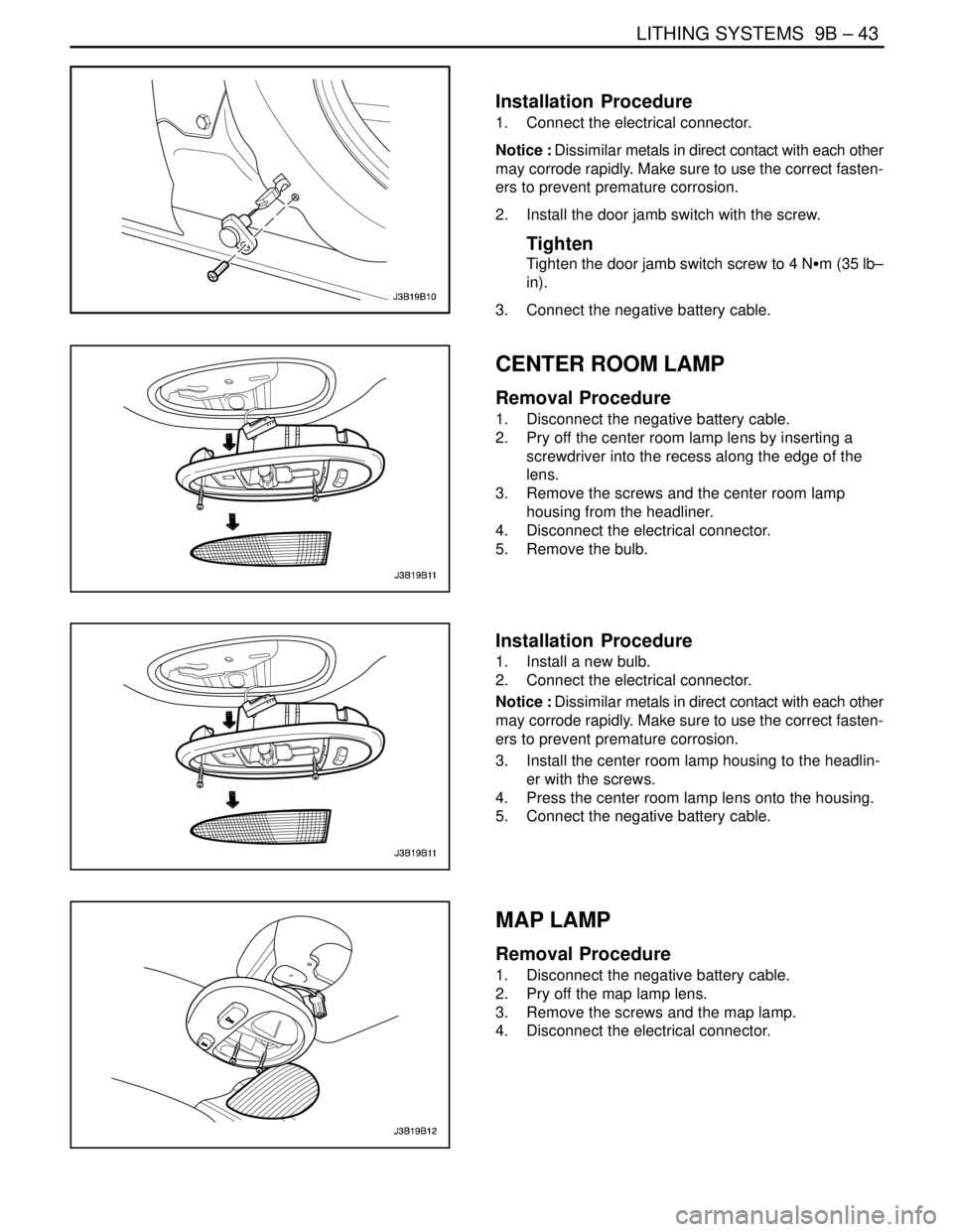
DOOR JAMB SWITCH
Removal Procedure
1. Disconnect the negative battery cable.
2. Remove the screw and the door jamb switch.
3. Disconnect the electrical connector.
Page 2269 of 2643
LITHING SYSTEMS 9B – 43
DAEWOO V–121 BL4
Installation Procedure
1. Connect the electrical connector.
Notice : Dissimilar metals in direct contact with each other
may corrode rapidly. Make sure to use the correct fasten-
ers to prevent premature corrosion.
2. Install the door jamb switch with the screw.
Tighten
Tighten the door jamb switch screw to 4 NSm (35 lb–
in).
3. Connect the negative battery cable.
CENTER ROOM LAMP
Removal Procedure
1. Disconnect the negative battery cable.
2. Pry off the center room lamp lens by inserting a
screwdriver into the recess along the edge of the
lens.
3. Remove the screws and the center room lamp
housing from the headliner.
4. Disconnect the electrical connector.
5. Remove the bulb.
Installation Procedure
1. Install a new bulb.
2. Connect the electrical connector.
Notice : Dissimilar metals in direct contact with each other
may corrode rapidly. Make sure to use the correct fasten-
ers to prevent premature corrosion.
3. Install the center room lamp housing to the headlin-
er with the screws.
4. Press the center room lamp lens onto the housing.
5. Connect the negative battery cable.
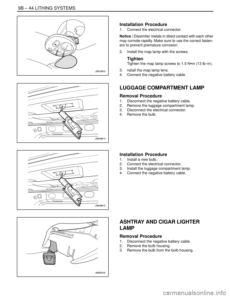
MAP LAMP
Removal Procedure
1. Disconnect the negative battery cable.
2. Pry off the map lamp lens.
3. Remove the screws and the map lamp.
4. Disconnect the electrical connector.
Page 2270 of 2643
9B – 44ILITHING SYSTEMS
DAEWOO V–121 BL4
Installation Procedure
1. Connect the electrical connector.
Notice : Dissimilar metals in direct contact with each other
may corrode rapidly. Make sure to use the correct fasten-
ers to prevent premature corrosion.
2. Install the map lamp with the screws.
Tighten
Tighten the map lamp screws to 1.5 NSm (13 lb–in).
3. nstall the map lamp lens.
4. Connect the negative battery cable.
LUGGAGE COMPARTMENT LAMP
Removal Procedure
1. Disconnect the negative battery cable.
2. Remove the luggage compartment lamp.
3. Disconnect the electrical connector.
4. Remove the bulb.
Installation Procedure
1. Install a new bulb.
2. Connect the electrical connector.
3. Install the luggage compartment lamp.
4. Connect the negative battery cable.
ASHTRAY AND CIGAR LIGHTER
LAMP
Removal Procedure
1. Disconnect the negative battery cable.
2. Remove the bulb housing.
3. Remove the bulb from the bulb housing.