brakes DAEWOO LACETTI 2004 Service Manual Online
[x] Cancel search | Manufacturer: DAEWOO, Model Year: 2004, Model line: LACETTI, Model: DAEWOO LACETTI 2004Pages: 2643, PDF Size: 80.54 MB
Page 1146 of 2643

ANTILOCK BRAKE SYSTEM 4F – 65
DAEWOO V–121 BL4
GENERAL DESCRIPTION AND SYSTEM
OPERATION
BASIC KNOWLEDGE REQUIRED
Before using this section, it is important that you have a ba-
sic knowledge of the following items. Without this knowl-
edge, it will be difficult to use the diagnostic procedures
contained in this section.
S Basic Electrical Circuits : You should understand
the basic theory of electricity and know the mean-
ing of voltage, current (amps), and resistance
(ohms). You should understand what happens in a
circuit with an open or shorted wire. You should be
able to read and understand a wiring diagram.
S Use of Circuit Testing Tools : You should know how
to use a test light and how to bypass components
to test circuits using fused jumper wires. You should
be familiar with a digital multimeter. You should be
able to measure voltage, resistance, and current,
and be familiar with the controls and how to use
them correctly.
ABS SYSTEM COMPONENTS
The ABS 5.3 Antilock Braking System (ABS) consists of
a conventional hydraulic brake system plus antilock com-
ponents. The conventional brake system includes a vacu-
um booster, master cylinder, front disc brakes, rear lead-
ing/trailing drum brakes, interconnecting hydraulic brake
pipes and hoses, brake fluid level sensor and the BRAKE
indicator.
The ABS components include a hydraulic unit, an elec-
tronic brake control module (EBCM), two system fuses,
four wheel speed sensors (one at each wheel), intercon-
necting wiring, the ABS indicator, the EBD indicator (which
is connected to the parking lamp) and the rear disk brakes.
See “ABS Component Locator” in this section for the gen-
eral layout of this system.
The hydraulic unit with the attached EBCM is located be-
tween the surge tank and the fire wall on the left side of the
vehicle.
The basic hydraulic unit configuration consists of hydraulic
check valves, two solenoid valves for each wheel, a hy-
draulic pump, two accumulators, and two damper. The hy-
draulic unit controls hydraulic pressure to the front calipers
and rear wheel cylinders by modulating hydraulic pressure
to prevent wheel lockup.
Nothing in the hydraulic unit or the EBCM is serviceable.
In the event of any failure, the entire ABS unit with at-
tached EBCM must be replaced. For more information, re-
fer to ”Base Braking Mode” and ”Antilock Braking Mode”
in this section.
BASE BRAKING MODE
The baseline braking mode of the ABS 5.3 system used
in this vehicle is a diagonal split system. In this system,
one master cylinder circuit supplies pressure to the right
front and the left rear brakes; the other circuit supplies
pressure to the left front and the right rear brakes. All
valves in the hydraulic modulator are in their normal, non–
energized positions as shown in the drawings found in
”ABS System Components” in this section.
Page 1150 of 2643

ANTILOCK BRAKE SYSTEM 4F – 69
DAEWOO V–121 BL4
EBD (ELECTRONIC BRAKE FORCE
DISTRIBUTION) SYSTEM
As an add–on logic to the ABS base algorithm, EBD works
in a range in which the intervention thresholds for ABS
control are not reached yet.
EBD ensures that the rear wheels are sensitively moni-
tored for slip with respect to the front axle. If slip is de-
tected, the inlet valves for the rear wheels are switched to
pressure hold to prevent a further increase in pressure at
the rear–wheel breaks, thus electronically reproducing a
pressure–reduction function at the rear–wheel brakes.
THE BENEFITS OF EBD
S Elimination of conventional proportioning valve.
S EBD utilizes the existing rear axle wheel speed
sensor to monitor rear wheel slip.
S Based on many variables in algorithm a pressure
hold, increase and/or decrease pulsetrain may be
triggered at the rear wheels insuring vehicle stabil-
ity.
S Vehicle approaches the ideal brake force distribu-
tion. (front to rear)
S Constant brake force distribution during vehicle life-
time.
S EBD function is monitored via ABS safety logic.
(conventional proportioning valves are not monitor-
able)
S ”Keep alive” function.
Page 1153 of 2643

SECTION : 4G
PARKING BRAKE
TABLE OF CONTENTS
SPECIFICATIONS4G–1 . . . . . . . . . . . . . . . . . . . . . . . . . .
Fastener Tightening Specifications 4G–1. . . . . . . . . .
MAINTENANCE AND REPAIR4G–2 . . . . . . . . . . . . . . .
ON–VEHICLE SERVICE 4G–2. . . . . . . . . . . . . . . . . . . . .
Parking Brake Adjustment Rear Drum Brakes 4G–2.
Parking Brake Adjustment Rear Disc Brakes 4G–2. . Parking Brake Lever 4G–3. . . . . . . . . . . . . . . . . . . . . . .
Parking Brake Cable 4G–5. . . . . . . . . . . . . . . . . . . . . . .
Parking Brake Handle 4G–8. . . . . . . . . . . . . . . . . . . . . .
GENERAL DESCRIPTION AND SYSTEM
OPERATION4G–9 . . . . . . . . . . . . . . . . . . . . . . . . . . . . . .
Parking Brake 4G–9. . . . . . . . . . . . . . . . . . . . . . . . . . . .
SPECIFICATIONS
FASTENER TIGHTENING SPECIFICATIONS
ApplicationNSmLb–FtLb–In
Parking Brake Cable–to–Underbody Side
Bracket bolts6–53
Parking Brake Lever Assembly–to–Vehicle
Underbody Bolts2216–
Parking Brake Switch–to–Parking Brake Le-
ver Screw4–35
Rear Brake Drum Detent Screw4–35
Page 1154 of 2643
4G – 2IPARKING BRAKE
DAEWOO V–121 BL4
MAINTENANCE AND REPAIR
ON–VEHICLE SERVICE
PARKING BRAKE ADJUSTMENT
REAR DRUM BRAKES
Adjustment Procedure
1. Adjust the rear brakes. Refer to Section 4E1, Rear
Disc Brakes.
2. Release the parking brake.
3. Raise and suitably support the vehicle.
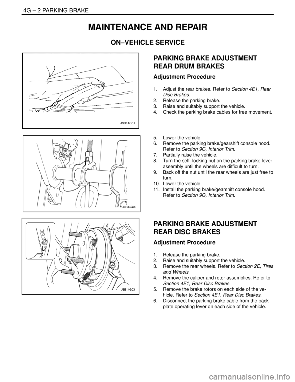
4. Check the parking brake cables for free movement.
5. Lower the vehicle
6. Remove the parking brake/gearshift console hood.
Refer to Section 9G, Interior Trim.
7. Partially raise the vehicle.
8. Turn the self–locking nut on the parking brake lever
assembly until the wheels are difficult to turn.
9. Back off the nut until the rear wheels are just free to
turn.
10. Lower the vehicle
11. Install the parking brake/gearshift console hood.
Refer to Section 9G, Interior Trim.
PARKING BRAKE ADJUSTMENT
REAR DISC BRAKES
Adjustment Procedure
1. Release the parking brake.
2. Raise and suitably support the vehicle.
3. Remove the rear wheels. Refer to Section 2E, Tires
and Wheels.
4. Remove the caliper and rotor assemblies. Refer to
Section 4E1, Rear Disc Brakes.
5. Remove the brake rotors on each side of the ve-
hicle. Refer to Section 4E1, Rear Disc Brakes.
6. Disconnect the parking brake cable from the back-
plate operating lever on each side of the vehicle.
Page 1155 of 2643
PARKING BRAKE 4G – 3
DAEWOO V–121 BL4
7. Inspect and replace any parts of doubtful strength
or quality. This can be shown by discoloration from
heat or stress.
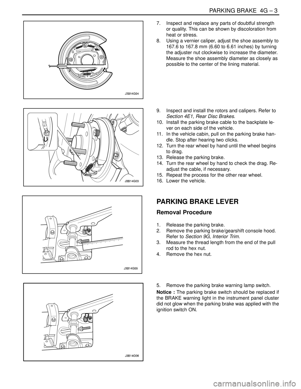
8. Using a vernier caliper, adjust the shoe assembly to
167.6 to 167.8 mm (6.60 to 6.61 inches) by turning
the adjuster nut clockwise to increase the diameter.
Measure the shoe assembly diameter as closely as
possible to the center of the lining material.
9. Inspect and install the rotors and calipers. Refer to
Section 4E1, Rear Disc Brakes.
10. Install the parking brake cable to the backplate le-
ver on each side of the vehicle.
11. In the vehicle cabin, pull on the parking brake han-
dle. Stop after hearing two clicks.
12. Turn the rear wheel by hand until the wheel begins
to drag.
13. Release the parking brake.
14. Turn the rear wheel by hand to check the drag. Re-
adjust the cable, if necessary.
15. Repeat the process for the other rear wheel.
16. Lower the vehicle.
PARKING BRAKE LEVER
Removal Procedure
1. Release the parking brake.
2. Remove the parking brake/gearshift console hood.
Refer to Section 9G, Interior Trim.
3. Measure the thread length from the end of the pull
rod to the hex nut.
4. Remove the hex nut.
5. Remove the parking brake warning lamp switch.
Notice : The parking brake switch should be replaced if
the BRAKE warning light in the instrument panel cluster
did not glow when the parking brake was applied with the
ignition switch ON.
Page 1156 of 2643
4G – 4IPARKING BRAKE
DAEWOO V–121 BL4
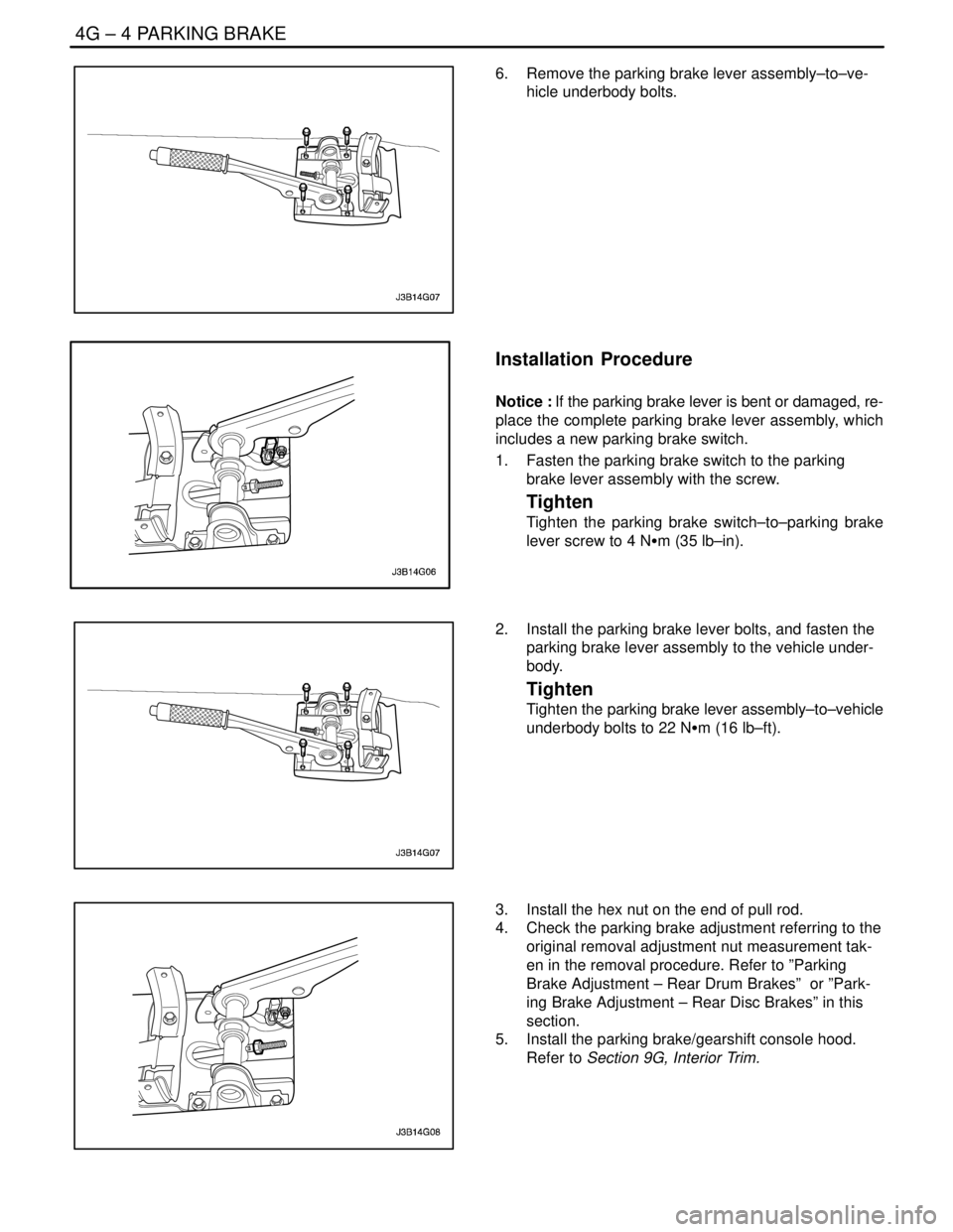
6. Remove the parking brake lever assembly–to–ve-
hicle underbody bolts.
Installation Procedure
Notice : If the parking brake lever is bent or damaged, re-
place the complete parking brake lever assembly, which
includes a new parking brake switch.
1. Fasten the parking brake switch to the parking
brake lever assembly with the screw.
Tighten
Tighten the parking brake switch–to–parking brake
lever screw to 4 NSm (35 lb–in).
2. Install the parking brake lever bolts, and fasten the
parking brake lever assembly to the vehicle under-
body.
Tighten
Tighten the parking brake lever assembly–to–vehicle
underbody bolts to 22 NSm (16 lb–ft).
3. Install the hex nut on the end of pull rod.
4. Check the parking brake adjustment referring to the
original removal adjustment nut measurement tak-
en in the removal procedure. Refer to ”Parking
Brake Adjustment – Rear Drum Brakes” or ”Park-
ing Brake Adjustment – Rear Disc Brakes” in this
section.
5. Install the parking brake/gearshift console hood.
Refer to Section 9G, Interior Trim.
Page 1157 of 2643
PARKING BRAKE 4G – 5
DAEWOO V–121 BL4
PARKING BRAKE CABLE
Removal Procedure
1. Remove the parking brake/gearshift console hood.
Refer to Section 9G, Interior Trim.
2. Release the parking brake lever and the hex nut on
the end of pull rod.
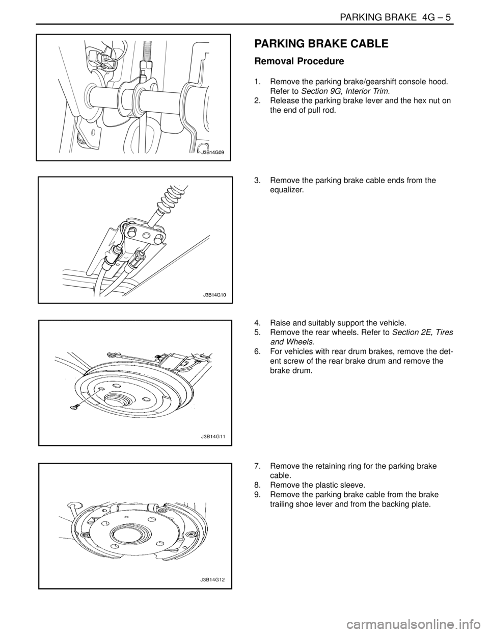
3. Remove the parking brake cable ends from the
equalizer.
4. Raise and suitably support the vehicle.
5. Remove the rear wheels. Refer to Section 2E, Tires
and Wheels.
6. For vehicles with rear drum brakes, remove the det-
ent screw of the rear brake drum and remove the
brake drum.
7. Remove the retaining ring for the parking brake
cable.
8. Remove the plastic sleeve.
9. Remove the parking brake cable from the brake
trailing shoe lever and from the backing plate.
Page 1158 of 2643
4G – 6IPARKING BRAKE
DAEWOO V–121 BL4
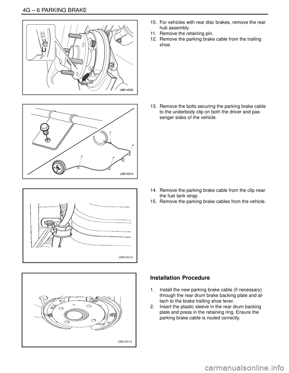
10. For vehicles with rear disc brakes, remove the rear
hub assembly.
11. Remove the retaining pin.
12. Remove the parking brake cable from the trailing
shoe.
13. Remove the bolts securing the parking brake cable
to the underbody clip on both the driver and pas-
senger sides of the vehicle.
14. Remove the parking brake cable from the clip near
the fuel tank strap.
15. Remove the parking brake cables from the vehicle.
Installation Procedure
1. Install the new parking brake cable (if necessary)
through the rear drum brake backing plate and at-
tach to the brake trailing shoe lever.
2. Insert the plastic sleeve in the rear drum backing
plate and press in the retaining ring. Ensure the
parking brake cable is routed correctly.
Page 1159 of 2643
PARKING BRAKE 4G – 7
DAEWOO V–121 BL4
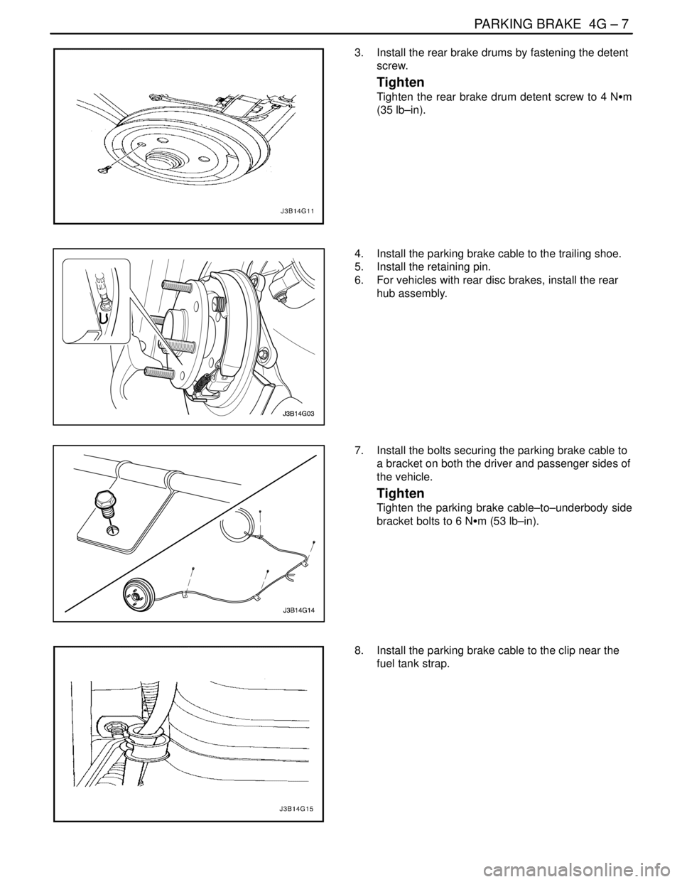
3. Install the rear brake drums by fastening the detent
screw.
Tighten
Tighten the rear brake drum detent screw to 4 NSm
(35 lb–in).
4. Install the parking brake cable to the trailing shoe.
5. Install the retaining pin.
6. For vehicles with rear disc brakes, install the rear
hub assembly.
7. Install the bolts securing the parking brake cable to
a bracket on both the driver and passenger sides of
the vehicle.
Tighten
Tighten the parking brake cable–to–underbody side
bracket bolts to 6 NSm (53 lb–in).
8. Install the parking brake cable to the clip near the
fuel tank strap.
Page 1397 of 2643

5A1 – 48IZF 4 HP 16 AUTOMATIC TRANSAXLE
DAEWOO V–121 BL4
The Lock up clutch should not apply unless the transaxle
has reached a minimum operating temperature of 8°C
(46°F) TRANS TEMP AND engine coolant temp of 50°C
(122°F).
5. Repeat steps 1–4 using several different throttle
angles.
Part Throttle Detent Downshift
At vehicle steeds of 55 to 65km/h (34 to 40mph) in Fourth
gear, quickly increase throttle angle to greater than 50%.
Verify that :
S TCC apply.
S Transaxle downshift to 3rd gear.
S Solenoid 1 turns ON to OFF.
S Solenoid 2 turns OFF.
Full Throttle Detent Downshift
At vehicle speeds of 55 to 65km/h (34 to 40mph)in Fourth
gear, quickly increase throttle angle to its maximum posi-
tion (100%)
Verify that :
S TCC release.
S Transaxle downshift to Second gear immediately.
S Solenoid 1 turns ON to OFF
S Solenoid 2 turns OFF.
Manual Downshifts
1. At vehicle speeds of 60km/h (40mph)in Fourth
gear, release accelerator pedal while moving gear
selector to Manual Third (3). Observe that :
S Transaxle downshift to Third gear immediately.
S Engine slows vehicle down.
2. Move gear selector back to overdrive(D) and accel-
erate to 31mph (50km/h). Release the accelerator
pedal and move the gear selector to Manual
First(1) and observe that :
S Transaxle downshift to second gear immediate-
ly.
S Engine slows vehicle down
Notice : A Manual First––Third Gear Ratio will occur at
high speeds as an upshift safety feature. Do not attempt
to perform this shift.
Coasting Downshifts
1. With the gear selector in Overdrive(D), accelerate
to Fourth gear with TCC applied.
2. Release the accelerator pedal and lightly apply the
brakes, and observe that :
S TCC release.
S Down shifts occur at speeds shown ON the shift
speed chart.
Manual Gear Range Selection
Upshifts in the manual gear ranges are controlled by the
shift solenoids. Perform the following tests by accelerating
at 25 percent TP sensor increments.
Manual Third (3)
S With vehicle stopped, move the gear selector to
Manual third(3) and accelerate to observe :
– 1–2 shift.
– 2–3 shift.
Manual Second (2)
S With vehicle stopped, move the gear selector to
Manual second(2) and accelerate to observe :
– 1–2 shift.
S Accelerate to 40km/h(25mph) and observe :
– 2–3 shift does not occur
– TCC does not apply
Manual First (1)
S With vehicle stopped, move gear selector to Manu-
al First(1). Accelerate to 30km/h(19mph) and ob-
serve :
– No upshifts occur
Reverse (R)
S With vehicle stopped, move gear selector to R(Re-
verse) and observe :
– Solenoid 1 is OFF
– Solenoid 2 is OFF
Use a scan tool to see if any transaxle trouble codes have
been set. Refer to ”Diagnostic Trouble Codes”in this sec-
tion and repair the vehicle as directed. After repairing the
vehicle, perform the hoist test and verify that the code has
not set again.
If the transaxle is not performing well and no trouble codes
have been set, there may be an intermittent condition.
Check all electrical connections for damage or a loose fit.
You also have to perform a snapshot test which can help
catch an intermittent condition that dose not occur long
enough to set a code.
You may want to read ”Electronic Component Diagnosis”
in this section to become familiar with transaxle conditions
caused by transaxle electrical malfunction.
If no trouble codes have been set and the condition is sus-
pected to be hydraulic, take the vehicle on a road test.
TORQUE CONVERTER LOCK–UP
CLUTCH(TCC) DIAGNOSIS
To properly diagnosis the lock–up clutch(TCC) system,
perform all electrical testing first and then the hydraulic
testing.
The TCC is applied by fluid pressure which is controlled by
a solenoid Located inside the valve body. The solenoid is
energized by completing an electrical circuit through a
combination of switches and sensors.