intake manifold DAEWOO NUBIRA 2004 Service Owner's Manual
[x] Cancel search | Manufacturer: DAEWOO, Model Year: 2004, Model line: NUBIRA, Model: DAEWOO NUBIRA 2004Pages: 2643, PDF Size: 80.54 MB
Page 108 of 2643
1.4L/1.6L DOHC ENGINE MECHANICAL 1C1 – 65
DAEWOO V–121 BL4
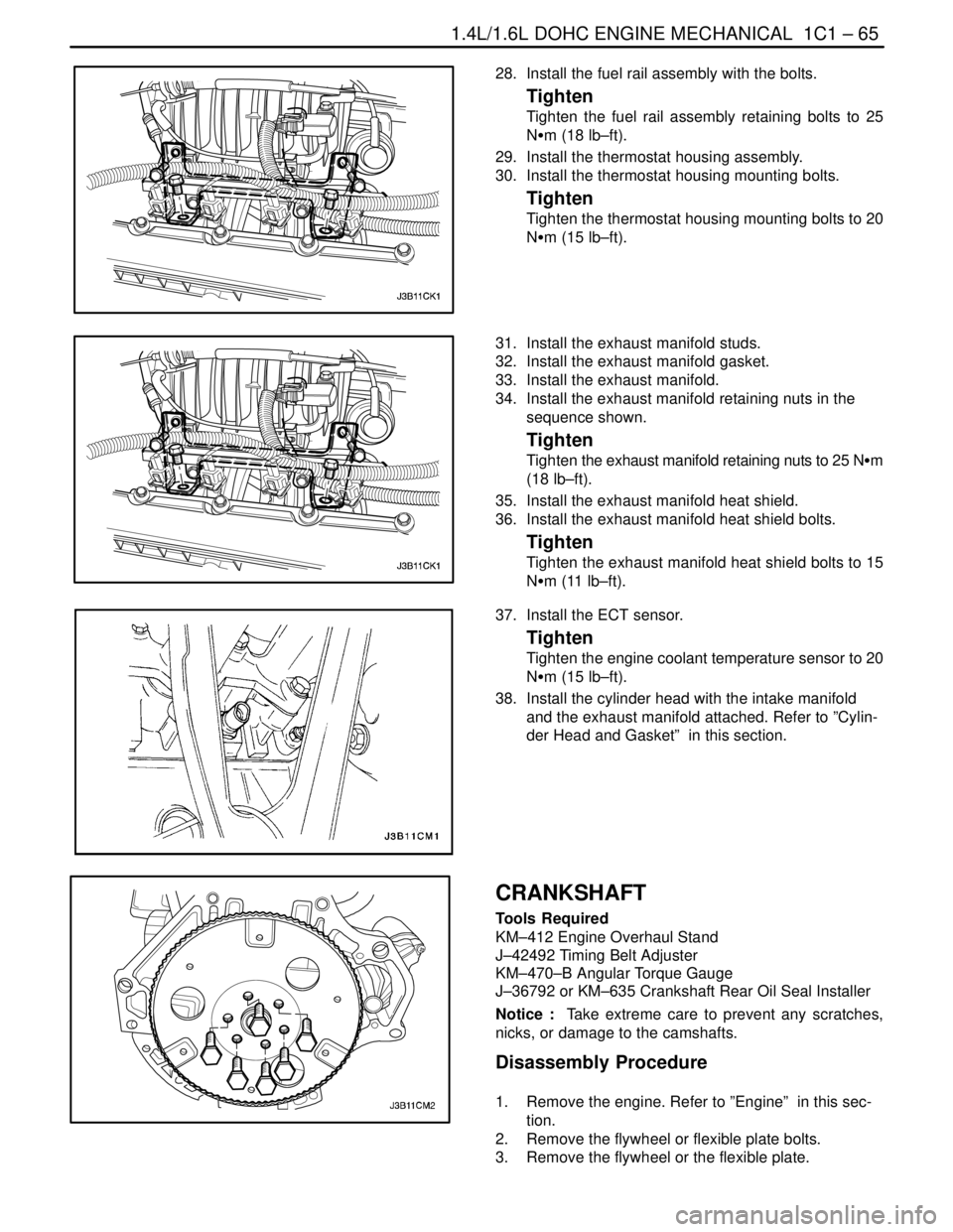
28. Install the fuel rail assembly with the bolts.
Tighten
Tighten the fuel rail assembly retaining bolts to 25
NSm (18 lb–ft).
29. Install the thermostat housing assembly.
30. Install the thermostat housing mounting bolts.
Tighten
Tighten the thermostat housing mounting bolts to 20
NSm (15 lb–ft).
31. Install the exhaust manifold studs.
32. Install the exhaust manifold gasket.
33. Install the exhaust manifold.
34. Install the exhaust manifold retaining nuts in the
sequence shown.
Tighten
Tighten the exhaust manifold retaining nuts to 25 NSm
(18 lb–ft).
35. Install the exhaust manifold heat shield.
36. Install the exhaust manifold heat shield bolts.
Tighten
Tighten the exhaust manifold heat shield bolts to 15
NSm (11 lb–ft).
37. Install the ECT sensor.
Tighten
Tighten the engine coolant temperature sensor to 20
NSm (15 lb–ft).
38. Install the cylinder head with the intake manifold
and the exhaust manifold attached. Refer to ”Cylin-
der Head and Gasket” in this section.
CRANKSHAFT
Tools Required
KM–412 Engine Overhaul Stand
J–42492 Timing Belt Adjuster
KM–470–B Angular Torque Gauge
J–36792 or KM–635 Crankshaft Rear Oil Seal Installer
Notice : Take extreme care to prevent any scratches,
nicks, or damage to the camshafts.
Disassembly Procedure
1. Remove the engine. Refer to ”Engine” in this sec-
tion.
2. Remove the flywheel or flexible plate bolts.
3. Remove the flywheel or the flexible plate.
Page 120 of 2643

1.4L/1.6L DOHC ENGINE MECHANICAL 1C1 – 77
DAEWOO V–121 BL4
GENERAL DESCRIPTION
AND SYSTEM OPERATION
CYLINDER HEAD AND GASKET
The cylinder head is made of an aluminum alloy. The cylin-
der head uses cross–flow intake and exhaust ports. A
spark plug is located in the center of each combustion
chamber. The cylinder head houses the dual camshafts.
CRANKSHAFT
The crankshaft has eight integral weights which are cast
with it for balancing. Oil holes run through the center of the
crankshaft to supply oil to the connecting rods, the bear-
ings, the pistons, and the other components. The end
thrust load is taken by the thrust washers installed at the
center journal.
TIMING BELT
The timing belt coordinates the crankshaft and the dual
overhead camshafts and keeps them synchronized. The
timing belt also turns the water pump. The timing belt and
the pulleys are toothed so that there is no slippage be-
tween them. There are two idler pulleys. An automatic ten-
sioner pulley maintains the timing belt’s correct tension.
The timing belt is made of a tough reinforced rubber similar
to that used on the serpentine accessory drive belt. The
timing belt requires no lubrication.
OIL PUMP
The oil pump draws engine oil from the oil pan and feeds
it under pressure to the various parts of the engine. An oil
strainer is mounted before the inlet of the oil pump to re-
move impurities which could clog or damage the oil pump
or other engine components. When the drive gear rotates,
the driven gear rotates. This causes the space between
the gears to constantly open and narrow, pulling oil in from
the oil pan when the space opens and pumping the oil out
to the engine as it narrows.
At high engine speeds, the oil pump supplies a much high-
er amount of oil than is required for lubrication of the en-
gine. The oil pressure regulator prevents too much oil from
entering the engine lubrication passages. During normal
oil supply, a coil spring and valve keep the bypass closed,
directing all of the oil pumped to the engine. When the
amount of oil being pumped increases, the pressure be-
comes high enough to overcome the force of the spring.This opens the valve of the oil pressure regulator, allowing
the excess oil to flow through the valve and drain back to
the oil pan.
OIL PAN
The engine oil pan is mounted to the bottom of the cylinder
block. The engine oil pan houses the crankcase and is
made of cast metal.
Engine oil is pumped from the oil pan by the oil pump. After
it passes through the oil filter, it is fed through two paths
to lubricate the cylinder block and the cylinder head. In one
path, the oil is pumped through the oil passages in the
crankshaft to the connecting rods, then to the pistons and
the cylinders. It then drains back to the oil pan. In the sec-
ond path, the oil is pumped through the oil passages to the
camshaft. The oil passes through the internal passage-
ways in the camshafts to lubricate the valve assemblies
before draining back to the oil pan.
EXHAUST MANIFOLD
A single four–port, rear–takedown manifold is used with
this engine. The manifold is designed to direct escaping
exhaust gases out of the combustion chambers with a
minimum of back pressure. The oxygen sensor is
mounted to the exhaust manifold.
INTAKE MANIFOLD
The intake manifold has four independent long ports and
uses inertial supercharging to improve engine torque at
low and moderate speeds. The plenum is attached to the
intake manifold.
CAMSHAFTS
This engine is a dual overhead camshaft (DOHC) type,
which means there are two camshafts. One camshaft op-
erates the intake valves, and the other camshaft operates
the exhaust valves. The camshafts sit in journals on the
top of the engine in the cylinder head and are held in place
by camshaft caps. The camshaft journals of the cylinder
head are drilled to create oil passages. Engine oil travels
to the camshafts under pressure where it lubricates each
camshaft journal. The oil returns to the oil pan through
drain holes in the cylinder head. The camshaft lobes are
machined into the solid camshaft to open and close the in-
take and the exhaust valves precisely the correct amount
at the correct time. The camshaft lobes are oiled by splash
action from pressurized oil escaping from the camshaft
journals.
Page 121 of 2643

SECTION : 1C2
1.8L DOHC ENGINE MECHANICAL
CAUTION : Disconnect the negative battery cable before removing or installing any electrical unit or when a tool
or equipment could easily come in contact with exposed electrical terminals. Disconnecting this cable will help
prevent personal injury and damage to the vehicle. The ignition must also be in LOCK unless otherwise noted.
TABLE OF CONTENTS
SPECIFICATIONS1C2–2 . . . . . . . . . . . . . . . . . . . . . . . . .
Engine Specifications 1C2–2. . . . . . . . . . . . . . . . . . . . .
Fastener Tightening Specifcations 1C2–4. . . . . . . . . .
SPECIAL TOOLS1C2–6 . . . . . . . . . . . . . . . . . . . . . . . . . .
Special Tools Table 1C2–6. . . . . . . . . . . . . . . . . . . . . . .
COMPONENT LOCATOR1C2–8 . . . . . . . . . . . . . . . . . . .
Upper End 1C2–8. . . . . . . . . . . . . . . . . . . . . . . . . . . . . . .
Lower End 1C2–10. . . . . . . . . . . . . . . . . . . . . . . . . . . . . .
MAINTENANCE AND REPAIR1C2–12 . . . . . . . . . . . . .
ON–VEHICLE SERVICE 1C2–12. . . . . . . . . . . . . . . . . . .
Camshaft Cover 1C2–12. . . . . . . . . . . . . . . . . . . . . . . . .
Cylinder Head and Gasket 1C2–13. . . . . . . . . . . . . . . .
Camshafts 1C2–22. . . . . . . . . . . . . . . . . . . . . . . . . . . . . .
Timing Belt Check and Adjust 1C2–24. . . . . . . . . . . . .
Timing Belt 1C2–28. . . . . . . . . . . . . . . . . . . . . . . . . . . . .
Oil Pan 1C2–32. . . . . . . . . . . . . . . . . . . . . . . . . . . . . . . . .
Oil Pump 1C2–33. . . . . . . . . . . . . . . . . . . . . . . . . . . . . . .
Engine Mount 1C2–37. . . . . . . . . . . . . . . . . . . . . . . . . . .
Intake Manifold 1C2–38. . . . . . . . . . . . . . . . . . . . . . . . . . Exhaust Manifold 1C2–41. . . . . . . . . . . . . . . . . . . . . . . .
Camshaft Gears 1C2–43. . . . . . . . . . . . . . . . . . . . . . . . .
Rear Timing Belt Cover 1C2–44. . . . . . . . . . . . . . . . . . .
Engine 1C2–46. . . . . . . . . . . . . . . . . . . . . . . . . . . . . . . . .
Pistions and Rods 1C2–51. . . . . . . . . . . . . . . . . . . . . . .
UNIT REPAIR 1C2–56. . . . . . . . . . . . . . . . . . . . . . . . . . . .
Cylinder Head and Valve Train Components 1C2–56.
Crankshaft 1C2–63. . . . . . . . . . . . . . . . . . . . . . . . . . . . . .
Crankshaft Bearing and Connecting Rod
Beadings – Gauging Plastics 1C2–72. . . . . . . . . . . .
GENERAL DESCRIPTION AND SYSTEM
OPERATION1C2–75 . . . . . . . . . . . . . . . . . . . . . . . . . . . .
Cylinder Head and Gasket 1C2–75. . . . . . . . . . . . . . . .
Crankshaft 1C2–75. . . . . . . . . . . . . . . . . . . . . . . . . . . . . .
Timing Belt 1C2–75. . . . . . . . . . . . . . . . . . . . . . . . . . . . .
Oil Pump 1C2–75. . . . . . . . . . . . . . . . . . . . . . . . . . . . . . .
Oil Pan 1C2–75. . . . . . . . . . . . . . . . . . . . . . . . . . . . . . . . .
Exhaust Manifold 1C2–75. . . . . . . . . . . . . . . . . . . . . . . .
Intake Manifold 1C2–75. . . . . . . . . . . . . . . . . . . . . . . . . .
Camshaft 1C2–75. . . . . . . . . . . . . . . . . . . . . . . . . . . . . . .
Page 123 of 2643

1.8L DOHC ENGINE MECHANICAL 1C2 – 3
DAEWOO V–121 BL4
Application Description
Diameter (All)
Out of Round (Maximum)48.970~ 48.988 mm (1.9279~1.9287 in.)
0.004 mm (0.00015 in.)
Cylinder Head:
Valve Stem Protrusion39.2~39.8 mm (1.54~1.56 in.)
Valve Guide Height13.7~14.0 mm (0.54~0.57 in.)
Overall Height134 ± 0.025 mm (5.2755~0.0009 in.)
Minimum Overall Height After Machining133.9 mm (5.27 in.)
Valve System:
Valve Lash CompensatorsHydraulic Tappet
Seat Runout (Maximum, All)0.03 mm (0.00118 in.)
Face Runout (Maximum, All)0.03 mm (0.00118 in.)
Valve Stem Diameter:
Intake
Exhaust5.945~5.960 mm (0.2341~0.2346 in.)
5.945~5.960 mm (0.2341~0.2346 in.)
Valve Diameter:
Intake
Exhaust32 ± 0.1 mm (1.2598 ± 0.0039 in.)
29 ± 0.1 mm (1.1417 ± 0.0039 in.)
Valve Seat Width:
Intake
Exhaust1.0~1.5 mm (0.039~0.059 in.)
1.7~2.2 mm (0.066~0.086 in.)
Valve Face Angle44°
Valve Guide Inside Diameter7.03~7.05 mm (0.276~0.277 in.)
Oil Pump:
Gear Lash0.10~0.20 mm (0.003~0.007 in.)
Outer Gear to Body0.11~0.19 mm (0.004~0.007 in.)
Outer Gear to Crescent0.40~0.50 mm (0.015~0.019 in.)
Inner Gear to Crescent0.35~0.40 mm (0.013~0.015 in.)
End Clearance0.030~0.10 mm (0.001~0.003 in.)
Sealants and Adhesives:
Rear Main Bearing CapGE p/n RTV 159
Camshaft Carrier to Cylinder HeadHN 1581 (Loctite® 515)
Oil Pan BoltsHN 1256 (Loctite® 242)
Oil Pump BoltsHN 1256 (Loctite® 242)
Oil Pan Pickup Tube BoltsHN 1256 (Loctite® 242)
Oil Gallery PlugHN 1256 (Loctite® 242)
Coolant Jacket Caps and Plugs (Freeze Plugs)HN 1756 (Loctite® 176)
Exhaust Manifold Studs/NutsAnti–seize Compound (HMC Spec HN1325)
Page 124 of 2643

1C2 – 4I1.8L DOHC ENGINE MECHANICAL
DAEWOO V–121 BL4
FASTENER TIGHTENING SPECIFCATIONS
ApplicationNSmLb–FtLb–In
Air Cleaner Housing Bolts10–89
Automatic Tensioner Bolt2518–
Camshaft Bearing Bridge and Oil Pan Scraper Bolts20 + 45°15 + 45°–
Camshaft Bearing Cap Bolts8–71
Camshaft Cover Bolts8–71
Charcoal Canister Purge and Exhaust Gas Recirculation Sole-
noid Bracket Bolt5–44
Connecting Rod Bearing Cap Bolts35
+ 45° + 15°26
+ 45° + 15°–
Coolant Bypass Housing and Mounting Bolts1511–
Crankshaft Bearing Cap Bolts50
+ 45° + 15°37
+ 45° + 15°–
Crankshaft Pulley Bolts2015–
Crankshaft Gear Bolt145
+ 30° + 15°107
+ 30° + 15°–
Cylinder Head Bolts25 + 90°
+ 90° + 90°18 + 90°
+ 90° + 90°–
Direct Ignition System Coil and Exhaust Gas Recirculation
Mounting Bracket Bolts2518–
Engine Mount Bracket Retaining Bolts and Nuts5541–
Engine Mount Retaining Bolts4533–
Engine–to–Intake Manifold Support Bracket Bolts2015–
Exhaust Camshaft Gear Bolt50
+ 60° + 15°37
+ 60° + 15°–
Exhaust Flex Pipe–to–Catalytic Converter or Connecting Pipe
Retaining Nuts3526–
Exhaust Flex Pipe–to–Exhaust Manifold Retaining Nuts3526–
Exhaust Manifold Heat Shield Bolts8–71
Exhaust Manifold Retaining Nuts2216–
Flexible Plate Bolts4533–
Flywheel Bolts65
+ 30° + 15°48
+ 30° + 15°–
Front Timing Belt Cover Bolts6–53
Generator–to–Intake Manifold Strap Bracket Bolt2216–
Generator–to–Intake Manifold Support Bracket Bolts3727–
Intake Camshaft Gear Bolt50
+ 60° + 15°37
+ 60° + 15°–
Intake Manifold Retaining Bolt and Nuts2216–
Intake Manifold Support Bracket Lower Bolt2518–
Intake Manifold Support Bracket Upper Bolts2518–
Lower Block Support Bracket and Splash Shield Bolts3526–
Oil Pan Drain Plug3526–
Oil Pan Flange–to–Transaxle Bolts4030–
Page 129 of 2643

1.8L DOHC ENGINE MECHANICAL 1C2 – 9
DAEWOO V–121 BL4
1. Bolt
2. Spark Plug Cover
3. Oil Filler Cap
4. Oil Filler Cap Seal
5. Bolt
6. Camshaft Cover
7. Camshaft Cover Gasket
8. Tappet Adjuster
9. Valve Key
10. Valve Spring Cap
11. Valve Spring
12. Valve Stem Seal
13. Valve Spring Seat
14. Valve Guide
15. Intake Valve Seat Ring
16. Exhaust Valve Seat Ring
17. Intake Valve
18. Exhaust Valve
19. Bolt
20. Front Camshaft Cap
21. Head Bolt
22. Bolt
23. Intermediate Camshaft Cap
24. Exhaust Gas Recirculation Adapter
25. Exhaust Gas Recirculation Adapter Gasket
26. Cylinder Head
27. Exhaust Manifold Gasket28. Exhaust Manifold
29. Nut
30. Exhaust Manifold Heat Shield
31. Cylinder Head Gasket
32. Bolt
33. Thermostat Housing
34. Thermostat Housing Gasket
35. Stud
36. Sleeve
37. Plug
38. Bolt
39. Camshaft Position Sensor
40. Oil Gallery Plug
41. Exhaust Camshaft
42. Seal Ring
43. Camshaft Gear
44. Washer
45. Camshaft Gear Bolt
46. Intake Camshaft
47. Intake Manifold Gasket
48. Intake Manifold
49. Throttle Body Gasket
50. Throttle Body
51. Nut
52. Charcoal Canister Purge Solenoid
53. Exhaust Gas Recirculation Solenoid
Page 137 of 2643
1.8L DOHC ENGINE MECHANICAL 1C2 – 17
DAEWOO V–121 BL4
53. Remove the generator–to–intake manifold support
bracket bolts at the cylinder head and the intake
manifold.
54. Remove the generator support bracket.
55. Remove the intake manifold–to–generator strap
bracket bolt and loosen the bolt on the generator.
56. Move the strap clear of the intake manifold.
57. Remove the charcoal canister purge (CCP) and
EGR solenoid bracket bolt and move the bracket
clear.
58. Disconnect the throttle cable at the throttle body
and the intake manifold.
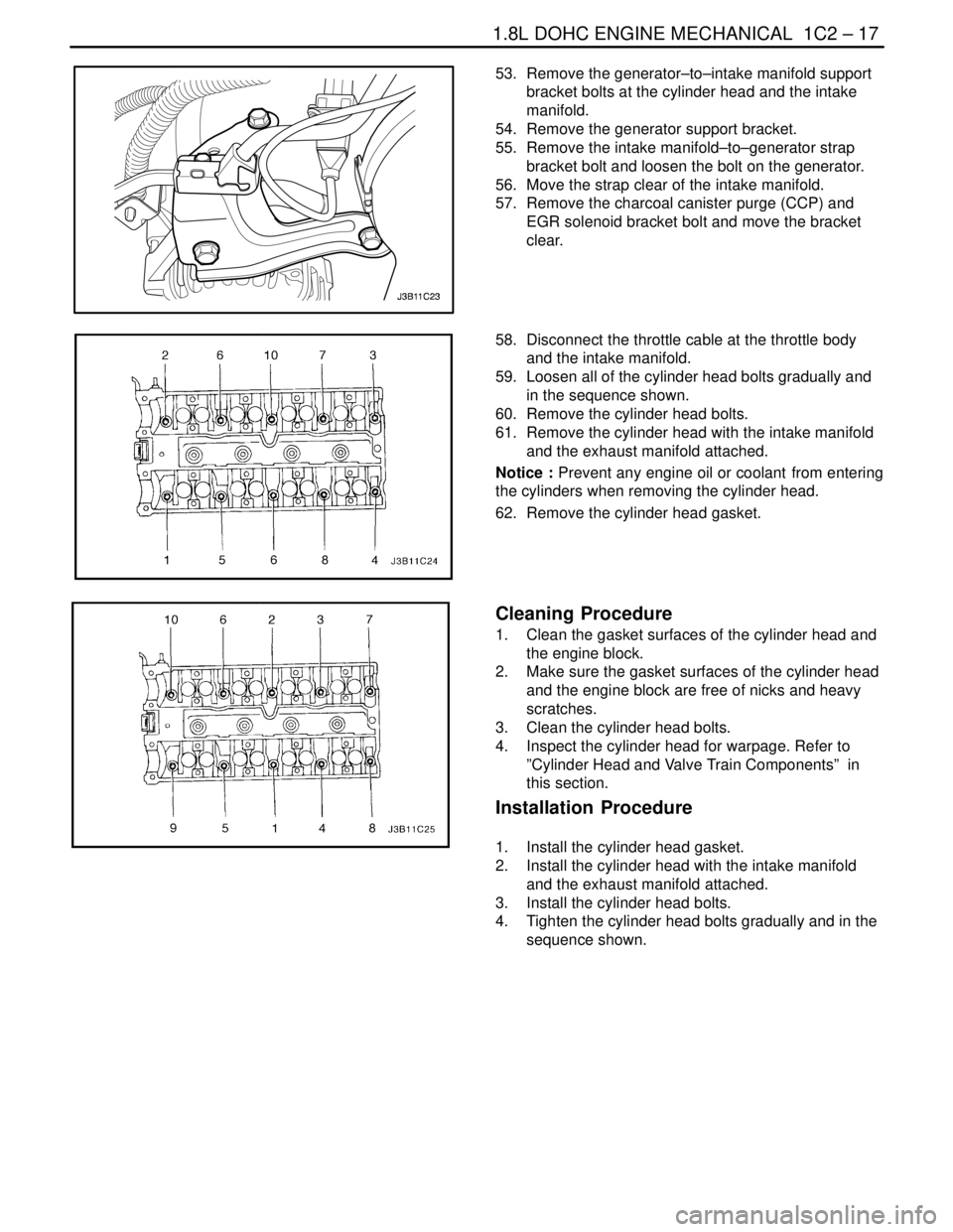
59. Loosen all of the cylinder head bolts gradually and
in the sequence shown.
60. Remove the cylinder head bolts.
61. Remove the cylinder head with the intake manifold
and the exhaust manifold attached.
Notice : Prevent any engine oil or coolant from entering
the cylinders when removing the cylinder head.
62. Remove the cylinder head gasket.
Cleaning Procedure
1. Clean the gasket surfaces of the cylinder head and
the engine block.
2. Make sure the gasket surfaces of the cylinder head
and the engine block are free of nicks and heavy
scratches.
3. Clean the cylinder head bolts.
4. Inspect the cylinder head for warpage. Refer to
”Cylinder Head and Valve Train Components” in
this section.
Installation Procedure
1. Install the cylinder head gasket.
2. Install the cylinder head with the intake manifold
and the exhaust manifold attached.
3. Install the cylinder head bolts.
4. Tighten the cylinder head bolts gradually and in the
sequence shown.
Page 138 of 2643
1C2 – 18I1.8L DOHC ENGINE MECHANICAL
DAEWOO V–121 BL4
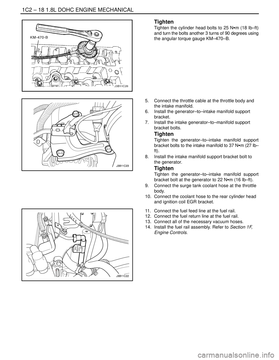
Tighten
Tighten the cylinder head bolts to 25 NSm (18 lb–ft)
and turn the bolts another 3 turns of 90 degrees using
the angular torque gauge KM–470–B.
5. Connect the throttle cable at the throttle body and
the intake manifold.
6. Install the generator–to–intake manifold support
bracket.
7. Install the intake generator–to–manifold support
bracket bolts.
Tighten
Tighten the generator–to–intake manifold support
bracket bolts to the intake manifold to 37 NSm (27 lb–
ft).
8. Install the intake manifold support bracket bolt to
the generator.
Tighten
Tighten the generator–to–intake manifold support
bracket bolt at the generator to 22 NSm (16 lb–ft).
9. Connect the surge tank coolant hose at the throttle
body.
10. Connect the coolant hose to the rear cylinder head
and ignition coil EGR bracket.
11. Connect the fuel feed line at the fuel rail.
12. Connect the fuel return line at the fuel rail.
13. Connect all of the necessary vacuum hoses.
14. Install the fuel rail assembly. Refer to Section 1F,
Engine Controls.
Page 139 of 2643
1.8L DOHC ENGINE MECHANICAL 1C2 – 19
DAEWOO V–121 BL4
15. Install the exhaust flex pipe retaining nuts at the
exhaust manifold studs.
Tighten
Tighten the exhaust flex pipe–to–exhaust manifold
retaining nuts to 35 NSm (26 lb–ft).
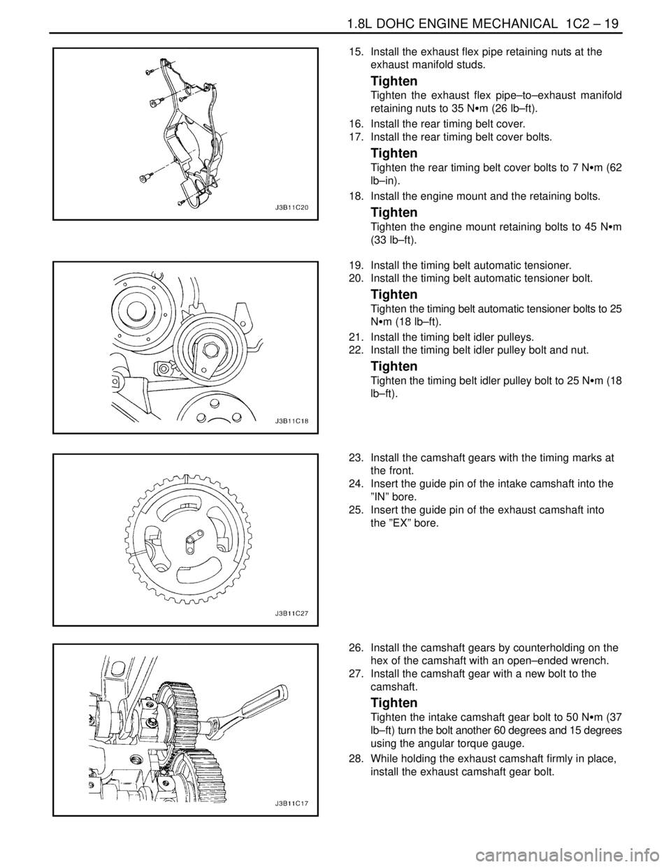
16. Install the rear timing belt cover.
17. Install the rear timing belt cover bolts.
Tighten
Tighten the rear timing belt cover bolts to 7 NSm (62
lb–in).
18. Install the engine mount and the retaining bolts.
Tighten
Tighten the engine mount retaining bolts to 45 NSm
(33 lb–ft).
19. Install the timing belt automatic tensioner.
20. Install the timing belt automatic tensioner bolt.
Tighten
Tighten the timing belt automatic tensioner bolts to 25
NSm (18 lb–ft).
21. Install the timing belt idler pulleys.
22. Install the timing belt idler pulley bolt and nut.
Tighten
Tighten the timing belt idler pulley bolt to 25 NSm (18
lb–ft).
23. Install the camshaft gears with the timing marks at
the front.
24. Insert the guide pin of the intake camshaft into the
”IN” bore.
25. Insert the guide pin of the exhaust camshaft into
the ”EX” bore.
26. Install the camshaft gears by counterholding on the
hex of the camshaft with an open–ended wrench.
27. Install the camshaft gear with a new bolt to the
camshaft.
Tighten
Tighten the intake camshaft gear bolt to 50 NSm (37
lb–ft) turn the bolt another 60 degrees and 15 degrees
using the angular torque gauge.
28. While holding the exhaust camshaft firmly in place,
install the exhaust camshaft gear bolt.
Page 158 of 2643
1C2 – 38I1.8L DOHC ENGINE MECHANICAL
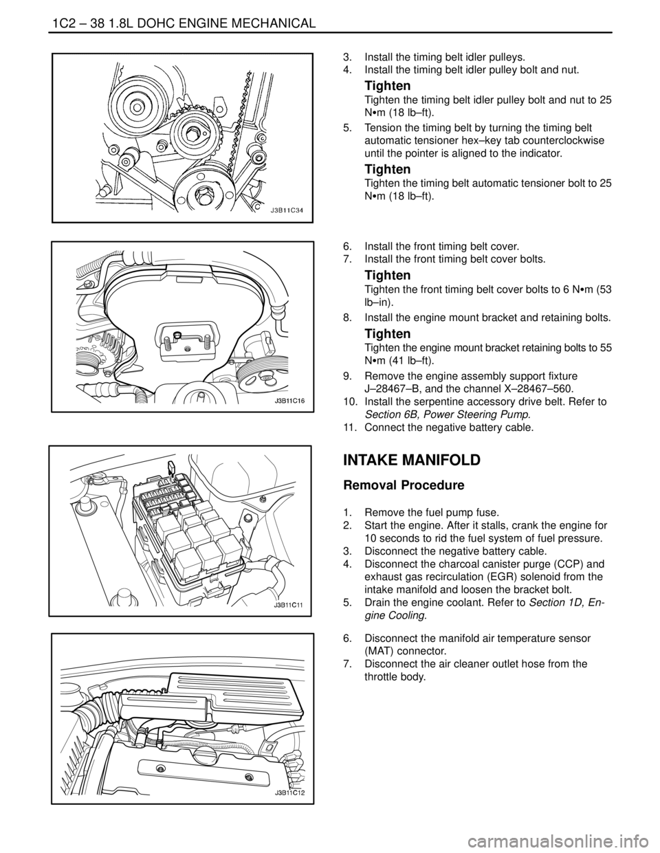
DAEWOO V–121 BL4
3. Install the timing belt idler pulleys.
4. Install the timing belt idler pulley bolt and nut.
Tighten
Tighten the timing belt idler pulley bolt and nut to 25
NSm (18 lb–ft).
5. Tension the timing belt by turning the timing belt
automatic tensioner hex–key tab counterclockwise
until the pointer is aligned to the indicator.
Tighten
Tighten the timing belt automatic tensioner bolt to 25
NSm (18 lb–ft).
6. Install the front timing belt cover.
7. Install the front timing belt cover bolts.
Tighten
Tighten the front timing belt cover bolts to 6 NSm (53
lb–in).
8. Install the engine mount bracket and retaining bolts.
Tighten
Tighten the engine mount bracket retaining bolts to 55
NSm (41 lb–ft).
9. Remove the engine assembly support fixture
J–28467–B, and the channel X–28467–560.
10. Install the serpentine accessory drive belt. Refer to
Section 6B, Power Steering Pump.
11. Connect the negative battery cable.
INTAKE MANIFOLD
Removal Procedure
1. Remove the fuel pump fuse.
2. Start the engine. After it stalls, crank the engine for
10 seconds to rid the fuel system of fuel pressure.
3. Disconnect the negative battery cable.
4. Disconnect the charcoal canister purge (CCP) and
exhaust gas recirculation (EGR) solenoid from the
intake manifold and loosen the bracket bolt.
5. Drain the engine coolant. Refer to Section 1D, En-
gine Cooling.
6. Disconnect the manifold air temperature sensor
(MAT) connector.
7. Disconnect the air cleaner outlet hose from the
throttle body.