torque DATSUN 210 1979 Service Manual
[x] Cancel search | Manufacturer: DATSUN, Model Year: 1979, Model line: 210, Model: DATSUN 210 1979Pages: 548, PDF Size: 28.66 MB
Page 391 of 548
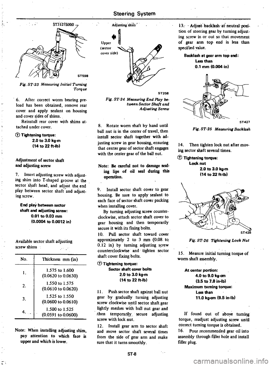
Fig
ST
23
Mea
uring
Initial
Turning
Torque
6
After
correct
worm
bearing
pre
load
has
been
obtained
remove
rear
cover
and
apply
sealant
on
housing
and
cover
sides
of
shims
Reinstall
rear
cover
with
shims
at
tached
under
cover
fJ
Tightening
torque
2
0
to
3
0
kg
m
14
to
22
fHbl
Adjustment
of
sector
shaft
and
adjusting
screw
7
Insert
adjusting
screw
with
adjust
ing
shUn
into
T
shaped
groove
at
the
sector
aft
head
and
adjust
the
end
play
between
sector
shaft
and
adjust
ing
screw
End
play
betwean
sector
shaft
and
IKljusting
screw
0
01
to
0
03
mm
0
0004
to
0
0012
in
Available
sector
shaft
adjusting
screw
shims
No
Thickness
mm
in
2
1
575
to
1
600
0
0620
to
0
0630
1
550
to
1
575
0
0610
to
0
0620
1
525
to
1
550
0
0600
to
0
0610
1
500
to
1
525
0
0591
to
0
0600
3
4
Note
When
installing
adjUsting
shim
pay
attention
to
which
face
is
upper
and
which
is
lower
Steering
System
Adjusting
shilli
Upper
1
sector
l
cover
side
ST258
Fig
ST
24
Measuri
End
l
UJy
tween
Sector
Shaft
and
AeVusting
Screw
8
Rotate
wonn
shaft
by
hand
until
ball
nut
is
in
the
center
of
travel
then
install
sector
shaft
together
with
ad
justing
screw
in
gear
housing
ensuring
that
center
gear
of
sector
shaft
engages
with
the
center
gear
of
the
ball
nut
Note
Be
careful
not
to
damage
seal
ing
lips
of
oil
seal
during
thi5
operation
9
Install
sector
shaft
cover
to
gear
chousing
Be
sure
to
apply
sealant
to
each
face
of
sector
shaft
cover
packing
when
installing
cover
By
turning
adjusting
screw
counter
clockwise
attach
sector
shaft
cover
to
gear
housing
and
then
temporarily
secure
it
with
its
futing
bolts
10
Pull
sector
shaft
toward
cover
approxUnately
2
to
3
mm
0
08
to
0
12
in
by
turning
adjusting
screw
counterclockwise
and
tighten
sector
shaft
cover
fIXing
bolts
fJ
Tightening
torque
Sector
shaft
co
er
bolts
2
0
to
3
0
kg
m
14
to
22
ft
Ib
II
Push
sector
shaft
against
ball
nut
gear
by
gradually
turning
adjusting
screw
clockwise
until
sector
shaft
gear
lightly
meshes
with
ball
nut
gear
and
then
temporarily
secure
adjusting
screw
with
lock
nut
12
Install
gear
arm
to
sector
shaft
and
move
sector
shaft
several
times
from
the
side
of
gear
ann
and
make
sure
that
it
turns
smoothly
SHl
13
Adjust
backIashat
neutral
posic
tion
of
steering
gear
by
turning
adjust
iog
screw
in
or
out
so
that
movement
of
gear
arm
top
end
is
less
than
specified
value
Backlash
at
gear
arm
top
end
Less
than
0
1
mm
0
004
in
ST
427
Fig
ST
25
Measuri
Bocklash
14
Then
tighten
lock
nut
after
mov
ing
sector
shaft
several
tUnes
fJ
Tightening
torqu
Lock
nut
2
0
to
3
0
kg
m
14
to
22
ft
Ibl
ST
428
Fig
ST
26
Tighteni
Loek
Nut
15
Measure
initial
turning
torque
of
wonn
shaft
assembly
At
center
portion
4
0
to
9
0
kt
c
m
3
5
to
7
8
in
lbl
Maximum
turning
torque
Less
than
11
0
kg
c
m
9
5
in
Ib
If
found
out
of
above
turning
torque
readjust
adjusting
screw
uniil
correct
turning
torque
is
obtained
16
Pour
recommended
gear
oil
into
assembly
through
fdler
hole
and
install
filler
plug
Page 392 of 548
Specified
rofill
capaeity
GearcaS8
0
28
liter
US
pt
Imp
ptl
Inatallatlon
Install
steering
gear
in
the
reverse
order
of
removal
Observe
the
following
instructions
e
Position
steering
gear
and
rubber
coupling
in
place
then
install
and
Steering
System
tighten
bolts
securing
steering
gear
housing
to
body
side
member
GJ
Tightening
torque
Steering
gear
hou
ing
to
body
id
member
7
0
to
8
0
ku
m
51
to
58
ft
Ibl
Rubber
coupling
to
worm
haft
4
0
to
5
0
kg
m
29
to
36
ft
Ibl
Note
a
Align
the
groove
in
wonn
haft
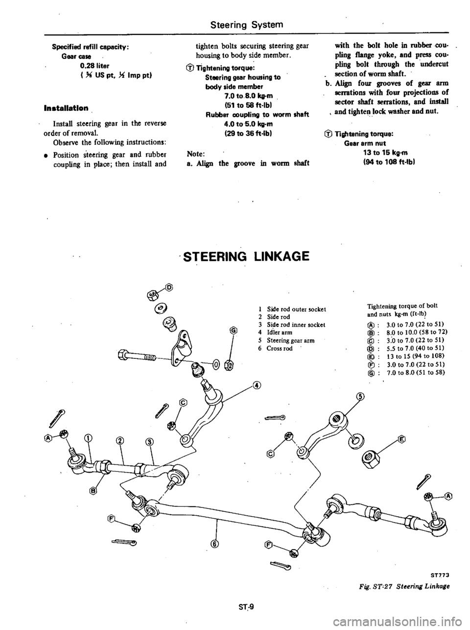
STEERING
LINKAGE
@
@
@
lID
I
O
@
6
1
Side
rod
outer
socket
2
Side
rod
3
Side
rod
inner
socket
4
Id
ler
arm
5
Steering
gear
arm
6
Cross
rod
@
with
the
bolt
hole
in
rubberoou
piing
flange
yoke
and
press
cou
pling
bolt
through
the
undercut
section
of
wonn
sheft
b
Align
four
grooves
of
gear
ann
serrations
with
four
projections
of
sector
haft
serrations
and
install
and
tighten
lock
washer
end
nut
GJ
Tightening
torque
Gelr
arm
nut
13
to
15
kg
m
94
to
108
ft
Ibl
Tightening
torque
afbalt
and
nuts
kg
m
ft
lb
@
3
0
to
7
0
22
to
51
@
8
0
to
10
0
58
to
72
@
3
0
to
7
0
22
to
51
@
5
5
to
7
0
40
to
51
@
13
to
15
94
to
108
Iti
3
0
to
7
0
22
to
51
@
7
0
to
8
0
51
to
58
@
@
@
@
ST
9
ST773
Fig
ST
27
St
ring
Linka
Page 393 of 548
REMOVAL
I
Jack
up
the
front
of
car
and
support
it
on
the
safety
stands
2
Remove
cotter
pins
and
nuts
fastening
side
rod
ball
studs
to
knuckle
arms
3
To
detach
side
rod
ball
studs
from
knuckle
arms
iJuert
Steering
BaII
Joint
Remover
HT72520000
between
them
and
separate
them
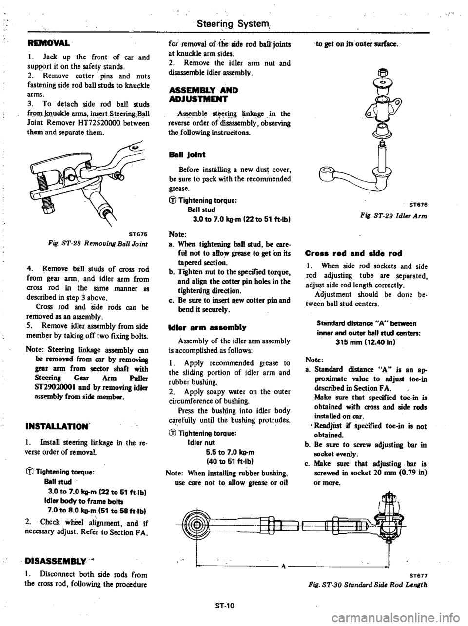
ST675
Fig
ST
28
Remouing
Ball
Joint
4
Remove
ball
studs
of
cross
rod
from
gear
arm
and
idler
arm
from
cross
rod
in
the
same
manner
as
descnbed
in
step
3
above
Cross
rod
and
side
rods
can
be
removed
as
an
assembly
5
Remove
idler
assembly
from
side
member
by
taking
off
two
fixing
bolts
Note
Steering
linkage
assembly
can
be
removed
from
CIC
by
rem
mng
gear
arm
from
sector
shaft
with
Steering
Gear
Arm
Puller
ST2902000
I
and
by
removing
idler
assembly
from
side
member
INSTAllATION
I
Install
steering
linkage
in
the
re
verse
order
of
removal
iJJ
Tightening
torque
Il8l1ltud
3
0
to
7
0
q
m
122
to
51
ft
Ibl
Idler
body
to
frame
bolts
7
0
to
8
0
q
m
151
to
58
ft
Ibl
2
Check
wheel
alignment
and
if
necessary
adjust
Refer
to
SectionF
A
DISASSEMBLY
I
Disconnect
both
side
rods
from
the
cross
rod
following
the
procedure
Steering
System
for
removal
of
the
side
rod
ball
joints
at
knuckle
arm
sides
2
Remove
the
idler
arm
nut
and
disassemble
idler
assembly
ASSEMBLY
AND
ADJUSTMENT
A
mble
st
rwg
linkage
in
the
reverse
order
of
disassembly
observing
the
following
instrucitons
Ban
Joint
Before
installing
a
new
dus
cover
be
sure
to
pack
with
the
recommended
grease
t
J
Tightening
torque
Ballltud
3
0
to
7
0
kg
m
122
to
51
ft
lbl
Note
a
When
tightening
ball
stud
be
care
ful
not
to
aBow
grease
to
get
On
its
tapered
section
b
Tighten
nut
to
the
specified
torque
and
align
the
cotter
pin
holes
in
the
tightening
direction
c
Be
sure
to
insert
new
cotter
pin
and
bend
it
securely
Idl
r
rm
mbl
Assembly
of
the
idler
arm
assembly
is
accomplished
as
follows
I
Apply
recommended
grease
to
the
sliding
portion
of
idler
arm
and
rubber
bushing
2
Apply
soapy
water
on
the
outer
circumference
of
bushing
Pre
ss
the
bushing
into
idler
body
carefully
until
the
bushin
protrudes
iJJ
Tightening
torque
Idler
nut
5
5
to
7
0
q
m
4010
51
ft
Ib
Note
When
installing
rubber
bushing
use
care
not
to
allow
grease
or
oil
Hj1
ST
10
to
get
on
its
onter
surface
ST676
Fig
ST
29
Idler
Arm
Cro
rod
nd
Id
rod
I
When
side
rod
sockets
and
side
rod
adjusting
tube
are
separated
adjust
side
rod
length
correctly
Adjustment
should
be
done
be
tween
ball
stud
centers
Standard
distance
AU
between
inner
and
outer
ballltud
conte
315
mm
12
40
in
Note
a
Standard
distance
A
i
an
ap
proximale
value
to
adjust
toe
in
descnbed
in
Section
FA
Maire
sure
tbat
specified
toe
in
is
obtained
with
O
OSs
and
side
rods
installed
on
car
ReadjUst
if
Specified
toe
in
is
not
obtained
b
Be
sure
to
screw
adjusting
bar
in
clret
evenly
c
Make
sure
that
adjusting
bar
is
screwed
in
socket
20
mm
0
79
in
or
more
I
lf
A
ST
77
Fig
ST
30
Standard
Side
Rod
Length
Page 394 of 548
2
Tighten
adjusting
bar
lock
nut
with
cross
and
side
rods
installed
on
car
Note
Lock
adjusting
bar
lock
nut
so
that
ball
joint
on
outer
socket
knuckle
arm
side
is
86019
with
respect
to
that
on
inner
socket
cross
rod
side
INSPECTION
AND
REPAIR
Ball
Joint
1
When
ball
stud
is
worn
or
axial
play
exists
replace
side
rod
socket
with
a
new
one
2
When
dust
cover
is
broken
or
Steering
System
deformed
be
sure
to
replace
with
a
new
one
Initial
turning
torque
Ball
joint
5
to
25
kg
em
4
3
to
21
7
ft
Ibl
Note
Check
idler
side
joint
grease
at
recommended
intervals
and
renew
if
necessary
To
renew
grease
change
screw
with
grease
nipple
and
apply
recommended
grease
to
joint
through
grease
nipple
until
grease
is
forced
out
between
dust
seal
and
joint
socket
Idler
erm
8ssembly
Check
rubber
bushing
of
idler
arm
ST
11
for
breakage
wear
or
play
and
if
necessary
replace
Note
Apply
grease
to
idler
ann
as
sembly
when
disassembled
Cross
rod
and
side
rod
Check
side
rod
and
cross
rod
for
breakage
bend
or
crack
and
replace
with
a
new
one
if
necessary
Fixing
location
Check
fIxing
location
nuts
and
cotter
pins
for
looseness
play
or
breakage
When
looseness
or
play
is
found
check
for
wear
on
tapered
portion
of
ball
stud
gear
arm
or
idler
arm
Page 395 of 548
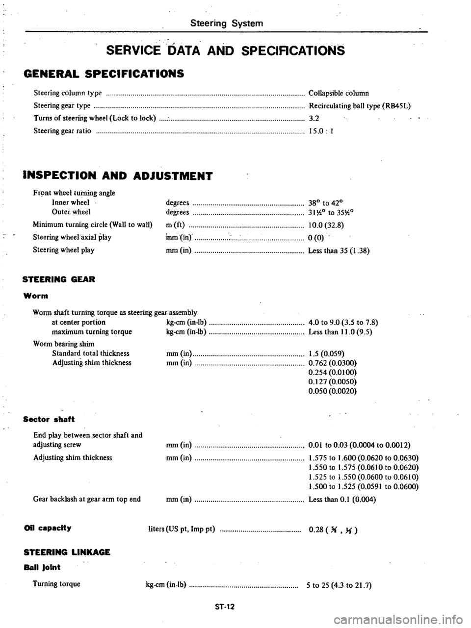
Steering
System
SERVICE
DATA
AND
SPECIRCATIONS
GENERAL
SPECIFICATIONS
Steering
column
type
Steering
gear
type
Turn
of
steering
wheel
Lock
to
lock
Steering
gear
ratio
CollapSIble
column
Recirculating
ball
type
RB45L
3
2
15
0
I
INSPECTION
AND
ADJUSTMENT
Front
wheel
turning
angle
Inner
wheel
Outer
wheel
Minimum
turning
circle
Wall
to
wall
Steering
wheel
axial
play
Steering
wheel
play
STEERING
GEAR
Worm
degrees
degrees
m
ft
nun
in
mm
in
380
to
420
31
i0
to
35
i0
10
0
32
8
0
0
Less
than
35
1
38
Worm
shaft
turning
torque
as
steering
gear
assembly
at
center
portion
kg
em
in
lb
maxUnum
turning
torque
kg
cm
in
lb
Worm
bearing
shUn
Standard
total
thickness
Adjusting
shim
thickness
Sector
ahaft
End
play
between
sector
shaft
and
adjusting
screw
Adjusting
shUn
thickness
Gear
backlash
at
gear
arm
top
end
on
capacity
STEERING
LINKAGE
Ball
Joint
Turning
torque
4
0
to
9
0
3
5
to
7
8
Less
than
11
0
9
5
mm
in
1
5
0
059
mm
in
0
762
0
0300
0
254
0
0100
0
127
0
0050
0
050
0
0020
mm
in
mm
in
om
to
0
Q3
0
0004
to
0
0012
1
575
to
1
600
0
0620
to
0
0630
1
550
to
1
575
0
06
0
to
0
0620
1
525
to
1
550
0
0600
to
0
0610
1
500
to
1
525
0
0591
to
0
0600
Less
than
0
1
0
004
mm
in
liters
US
pt
Imp
pt
0
28
M
kg
cm
in
lb
5
to
25
4
3
to
21
7
ST
12
Page 396 of 548
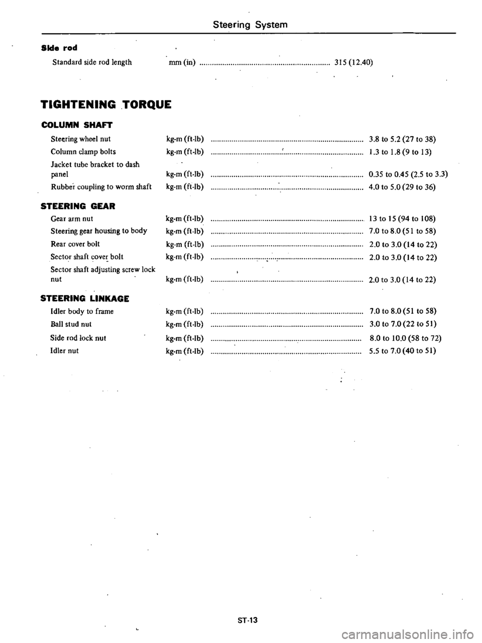
Steering
System
Side
rod
Standard
side
rod
length
mm
in
315
12
40
TIGHTENING
TORQUE
COLUMN
SHAFT
Steering
wheel
nut
kg
m
ft
lb
3
8
to
5
2
27
to
38
Column
clamp
bolts
kg
m
ft
lb
I
3
to
1
8
9
to
13
Jacket
tube
bracket
to
dash
panel
kg
m
ft
lb
0
35
to
0
45
2
5
to
3
3
Rubber
coupling
to
worm
shaft
kg
m
ft
lb
4
0
to
5
0
29
to
36
STEERING
GEAR
Gear
arm
nut
kg
m
ft
lb
13
to
15
94
to
108
Steering
gear
housing
to
body
kg
m
ft
lb
7
0
to
8
0
51
to
58
Rear
cover
bolt
kg
m
ft
lb
2
0
to
3
0
14
to
22
Sector
shaft
cover
bolt
kg
m
ft
lb
2
0
to
3
0
14
to
22
Sector
shaft
adjusting
screw
lock
nut
kg
m
ft
lb
2
0
to
3
0
14
to
22
STEERING
LINKAGE
Idler
body
to
frame
kg
m
ft
lb
7
0
to
8
0
51
to
58
Ball
stud
nut
kg
m
ft
lb
3
0
to
7
0
22
to
51
Side
rod
lock
nut
kg
m
ft
lb
8
0
to
10
0
58
to
72
Idler
nut
kg
m
ft
lb
5
5
to
7
0
40
to
51
ST
13
Page 398 of 548
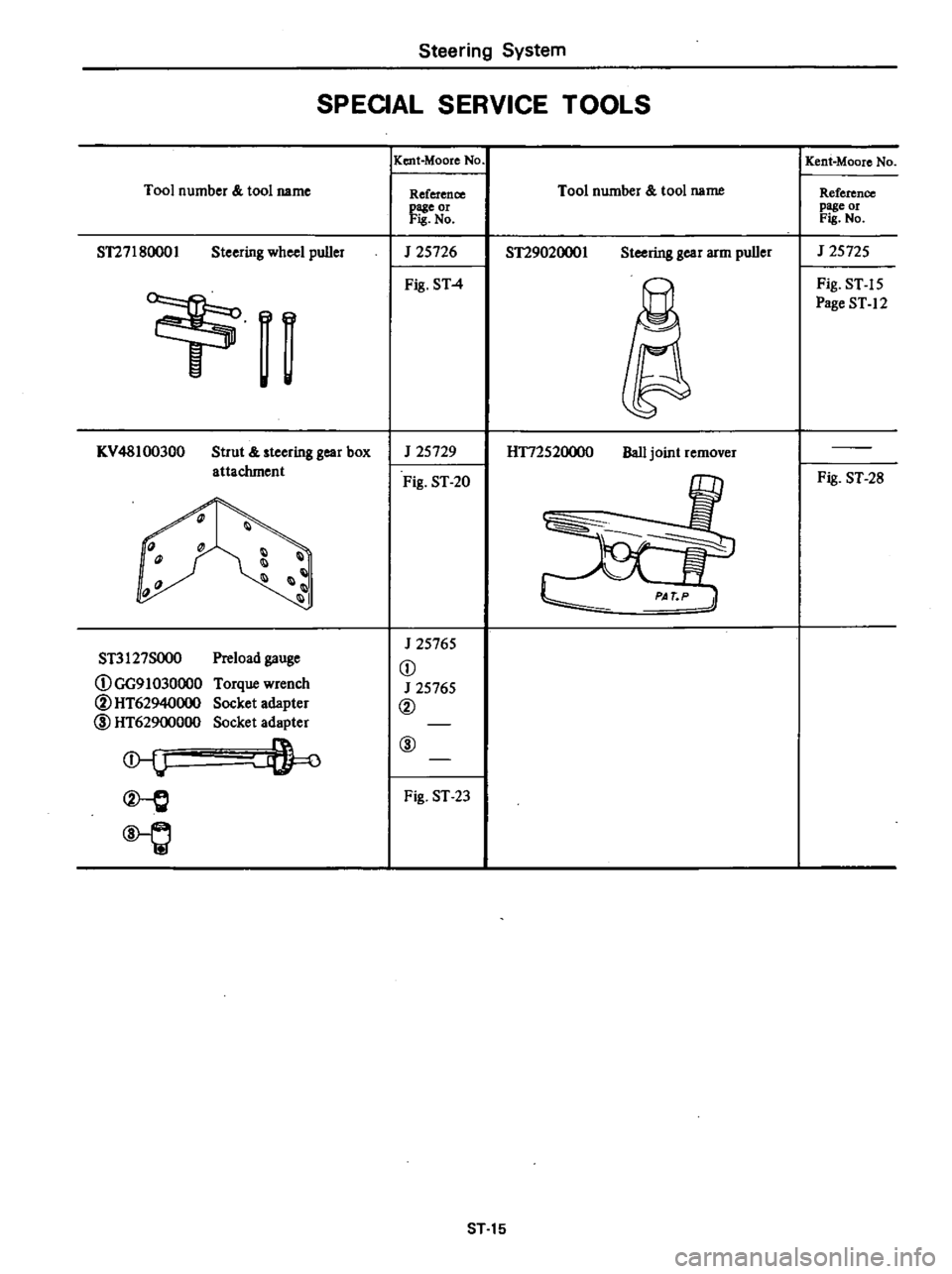
Steering
System
SPEOAL
SERVICE
TOOLS
Tool
number
tool
name
ST27180001
Steering
wheel
puller
n
I
KV
48100300
Strut
steering
gear
box
attachment
1l
1
III
11
Preload
gauge
Torque
wrench
Socket
adapter
Socket
adapter
ST3127SOO0
DGG91030000
@HT62940000
l
HT62900000
l
Q
IKent
Moore
No
Reference
page
or
Fis
No
J
25726
Fig
ST
4
J
25729
Fig
ST
20
J
25765
D
J
25765
@
@
Fig
ST
23
Tool
number
tool
name
ST29020001
Steering
gear
arm
puller
H172520000
Ball
joint
remover
ST
15
Kent
Moore
No
Reference
page
or
Fis
No
J
25725
Fig
ST
15
Page
ST
12
Fig
ST
28
Page 402 of 548

m
A
IlQ
J
i
t
3
Q
it
t
t
m
S
Canilter
pUlse
line
B
tt
c
D
e
D
1
Fuel
tank
2
Drain
plug
3
Filler
hose
4
Ventilation
hose
5
Breather
hose
6
Fuel
tank
gauge
unit
7
Fuel
return
tube
8
Fuel
outlet
tube
9
Evaporative
tubo
10
Fuel
tank
protector
11
Fuel
strainer
12
Carbon
canister
Tightening
torque
kg
m
ft
lb
@
1
6
to
2
4
12
10
17
n
I
O
V
0
3
l
I
c
GO
en
e
C2
m
r0
C
C
t
m
s
m
l
CO
S
C1
C
l
o
l
a
j
1
C1
Q
O
m
r
ll
c
Ul
CIl
Ul
C1
3
VI
Page 404 of 548

Engine
Control
f1lel
Exhaust
Systems
flow
be
directed
toward
atmosphere
side
2
Blow
air
tluough
connector
on
atmosphere
side
Air
flow
should
be
smoothly
directed
toward
fuel
tank
3
If
cbeck
valve
is
suspected
of
not
being
properly
functioning
in
steps
I
and
2
above
replace
To
fuel
tank
FE477
Pressure
valve
Vacuum
valve
Return
spring
Fig
FE
6
Checking
Check
Valve
INSTALLATION
Install
any
parts
of
the
fuel
system
in
the
reverse
order
of
removal
Ob
serve
the
following
notes
Note
a
Install
hose
clamps
securely
Do
not
tighten
excessively
to
avoid
dam
aging
hoses
b
Fasten
clips
holding
fuel
tube
on
underbody
securely
Failure
to
fol
low
this
caution
could
result
in
damage
to
the
surface
of
fuel
tube
c
Do
not
kink
or
twist
hOse
and
tube
when
they
are
routed
d
Run
the
engine
and
check
for
leaks
at
connections
FUEL
TANK
Not
InstaU
fuel
filler
hose
after
fuel
tank
has
been
mounted
in
place
Failure
to
foUow
this
rule
could
result
in
leakage
from
around
hose
connections
Do
not
twist
or
smash
vent
hoses
when
they
are
routed
Be
sure
to
retain
them
with
clips
securely
FE
6
@
Tightening
torque
Drain
plug
1
6
to
2
4
kg
m
112
tn
17
ft
bl
Fuel
tank
0
8
to
1
2
kll
m
15
8
to
8
7
ft
Ibl
FUEL
TANK
GAUGE
UNIT
Note
When
installing
fuel
tank
gauge
unit
aJign
the
projection
of
tank
gauge
unit
with
the
notch
in
fuel
tank
and
tighten
it
securely
Be
sure
to
instaU
tank
gauge
unit
with
O
ring
in
place
CHECK
VALVE
Note
When
installing
check
valve
be
careful
of
its
designated
direction
See
Fig
FE
Page 405 of 548

TI
m
3
S
3
a
3
c
1
3
2
m
N
i
ClI@
@
@
7Jr
iJ
@
Aut
omatic
transmission
equipped
models
@
r
I
5
6
1
Front
exhaust
tube
2
Catalytic
converter
3
Rear
exhaust
tube
4
Exhaust
mounting
insulator
S
Rear
exhaust
tube
shelter
6
Converter
lower
shelter
I
@
7
Converter
upper
shelter
8
Exhaust
mounting
bracket
9
V
bolt
clamp
10
U
bolt
housing
calmp
11
Gusset
12
Exhaust
tail
mounting
bracket
13
Muffler
clamp
ring
rubber
@@
@
@
@
l
@
Tightening
torque
kg
m
ft
lb
@
2
0
to
2
6
14
to
19
@
3
2
t04
3
23
to
31
@
1
6
to
2
t
12
to
15
@
0
8
to
1
2
5
8
to
8
7
@
0
3
to
0
5
2
2
to
3
6
e
a
8
O
6
l
c
a
8
l
m
X
c
en
4
en
en
4
m
s
m
co
i
CD
o
a
21
CD
l2
m
T
c
Ul
CD
3