length DATSUN 210 1979 Service Manual
[x] Cancel search | Manufacturer: DATSUN, Model Year: 1979, Model line: 210, Model: DATSUN 210 1979Pages: 548, PDF Size: 28.66 MB
Page 42 of 548
CYLINDER
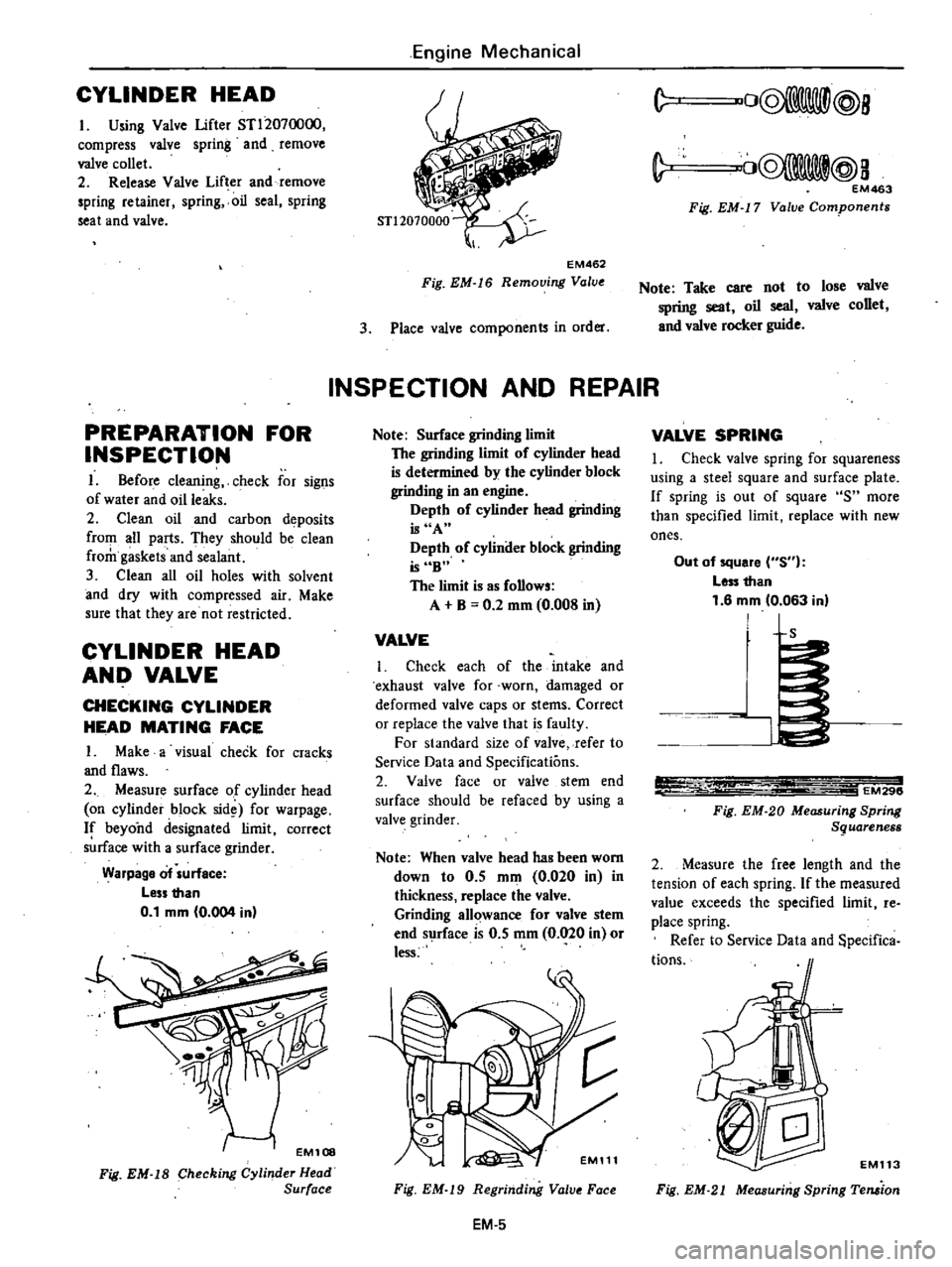
HEAD
I
Using
Valve
lifter
STl2070000
compress
valve
spring
and
remove
valve
collet
2
Release
Valve
Lifter
and
remove
spring
retainer
spring
oil
seal
spring
seat
and
valve
PREPARATION
FOR
INSPECTION
I
8efore
cleaning
check
for
signs
of
water
and
oille
s
2
Clean
oil
and
carbon
deposits
from
all
parts
They
should
be
clean
from
gaskets
and
sealant
3
Clean
all
oil
holes
with
solvent
and
dry
with
compressed
air
Make
sure
that
they
are
not
restricted
CYLINDER
HEAD
AND
VALVE
CHECKING
CYLINDER
HEAD
MATING
FACE
I
Make
a
visual
check
for
cracks
and
flaws
2
Measure
surface
of
cylinder
head
on
cylinder
block
sid
for
warpage
If
beyond
designated
limit
correct
s
rface
with
a
surface
grinder
Warpage
of
urfece
Less
than
0
1
mm
0
004
in
EM108
Fig
EM
IS
Checking
Cylinder
Head
Surface
Engine
Mechanical
EM462
Fig
EM
16
Removing
Value
3
Place
valve
components
in
order
INSPECTION
AND
REPAIR
Note
Surface
grinding
limit
The
grinding
limit
of
cylinder
head
is
determined
by
the
cylinder
block
grinding
in
an
engine
Depth
of
cylinder
head
grinding
is
A
Depth
of
cylinder
block
grinding
is
6B
The
limit
is
as
follows
A
B
0
2
mm
0
008
in
VALVE
i
Check
each
of
the
intake
and
exhaust
valve
for
worn
damaged
or
deformed
valve
caps
or
stems
Correct
or
replace
the
valve
that
is
faulty
For
standard
size
of
valve
refer
to
Service
Data
and
Specifications
2
Valve
face
or
valve
stem
end
surface
should
be
refaced
by
using
a
valve
grinder
Note
When
valve
head
has
been
worn
down
to
0
5
mm
0
020
in
in
thickness
replace
the
valve
Grinding
allowance
for
valve
stem
end
surface
is
0
5
mm
0
020
in
or
less
c
EM111
Fig
EM
19
Regrinding
Valve
Face
EM
5
C
vO@
lll@8
C
CQ8@
a
EM463
Fig
EM
17
Valve
Components
Note
Take
care
not
to
lose
valve
spring
seat
oil
seal
valve
collet
and
valve
rocker
guide
VALVE
SPRING
I
Check
valve
spring
for
squareness
using
a
steel
square
and
surface
plate
If
spring
is
out
of
square
S
more
than
specified
limit
replace
with
new
ones
Out
of
square
S
Less
than
1
6
mm
0
063
inl
L
1
EM296
Fig
EM
20
Measuring
Spring
Sguareness
2
Measure
the
free
length
and
the
tension
of
each
spring
If
the
measured
value
exceeds
the
specified
limit
re
place
spring
Refer
to
Service
Data
and
pecifica
tions
EMl13
Fig
EM
21
Measuring
Spring
Teruion
Page 46 of 548
Note
If
cylinder
bore
has
worn
beyond
the
wear
limit
use
cylinder
liner
Undersize
cylinder
liners
are
avail
able
for
service
Interference
fit
of
cylinder
liner
in
cylinder
block
ahould
be
0
08
to
0
09
mm
0
003
I
to
0
0035
in
PISTON
PISTON
PIN
AND
PISTON
RING
I
Remove
carbon
from
piston
and
ring
grooves
with
a
carbon
scraper
and
a
curved
steel
wire
The
wire
will
be
useful
in
cleaning
bottom
land
of
ring
groove
Clean
out
oil
slots
in
bottom
land
of
oil
ring
groove
2
Check
for
damage
scratches
and
wear
Replace
if
fault
is
detected
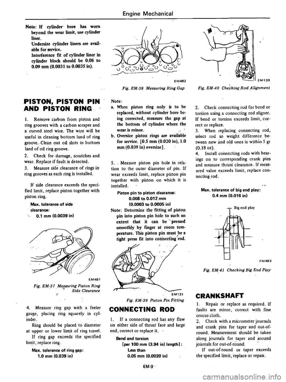
3
Measure
side
clearance
of
rings
in
ring
grooves
as
each
ring
is
installed
If
side
clearance
exceeds
the
speci
fied
limit
replace
piston
together
with
piston
ring
Max
tolerance
of
side
clearance
0
1
mm
0
0039
in
Engine
Mechanical
u
EM482
Fig
EM
38
Measuring
Ring
Gap
Note
a
When
piston
ring
only
is
to
be
replaced
without
cylinder
bore
be
ing
corrected
measure
the
gap
at
the
bottom
of
cylinder
where
the
wear
is
minor
b
Oversize
piston
rings
are
available
for
service
0
5
mm
0
020
in
1
0
mm
0
039
in
oversize
5
Measure
piston
pin
hole
in
rela
tion
to
the
outer
diameter
of
pin
If
wear
exceeds
limit
replace
piston
pin
together
with
piston
on
which
it
is
installed
Piston
pin
to
piston
clearance
O
OOS
to
0
012
mm
0
0003
to
0
0005
in
Note
Determine
the
fitting
of
piston
pin
into
piston
pin
hole
to
such
an
extent
that
it
can
be
pressed
smoothly
by
fmger
at
room
tem
perature
This
piston
pin
must
be
a
tight
press
fit
into
connecting
rod
EM481
Fig
EM
37
Me
suring
Piston
Ring
Side
Clearance
4
Measure
ring
gap
with
a
feeler
gauge
placing
ring
squarely
in
cyl
inder
Ring
should
be
placed
to
diameter
at
upper
or
lower
limit
of
ring
travel
If
ring
gap
exceeds
the
specified
limit
replace
ring
Max
tolerance
of
ring
gap
1
0
mm
0
039
in
EM131
Fig
EM
39
Piston
Pin
Fitting
CONNECTING
ROD
1
If
a
connecting
rod
has
any
flaw
on
either
side
of
thrust
face
and
large
end
correct
or
replace
it
Bend
and
torsion
per
100
mm
3
94
in
length
Less
than
0
05
mm
0
0020
in
EM
9
EM133
Fig
EM
40
Checking
Rod
Alignment
2
Check
connecting
rod
for
bend
or
torsion
using
a
connecting
rod
aligner
If
bend
or
torsion
exceeds
limit
cor
rect
or
replace
3
When
replacing
connecting
rod
select
rod
so
weight
difference
be
tween
new
and
old
ones
is
within
5
gr
0
180z
4
Install
connecting
rods
with
bear
iogs
on
to
corresponding
crank
pins
and
measure
thrust
clearance
If
meas
ured
value
exceeds
limit
replace
con
necting
rod
Max
tolerance
of
big
end
play
0
4
mm
0
016
in
l
Big
end
play
l
t
t
EM483
Fig
EM
41
Checking
Big
End
Pwy
CRANKSHAFT
I
Repair
or
replace
as
required
If
faults
are
minor
correct
with
fine
crocus
cloth
2
Check
with
a
micrometer
journals
and
crank
pins
for
taper
and
out
of
round
Measurement
should
be
taken
along
journals
for
taper
and
around
journals
for
out
of
round
If
out
of
round
or
taper
exceeds
the
specified
limit
replace
or
repair
Page 56 of 548
Engine
Mechanical
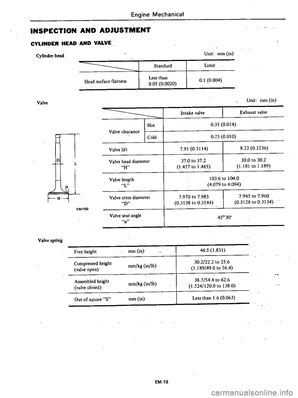
INSPECTION
AND
ADJUSTMENT
CYLINDER
HEAD
AND
VALVE
Cylinder
head
Unit
mm
in
Standard
Limit
Head
surface
flatness
Less
than
0
05
0
0020
0
1
0
004
Valve
Unit
mm
in
j
I
Hot
Valve
clearance
I
Cold
Intake
valve
Exhaust
valve
0
35
0
014
0
25
0
010
Valve
lift
7
91
0
3114
8
22
0
3236
H
37
0
to
37
2
1
457
to
1
465
30
0
to
30
2
1
181
to
1
189
D
L
Valve
head
diameter
a
H
Valve
length
L
103
6
to
104
0
4
079
to
4
094
D
7
970
to
7
985
0
3138
to
0
3144
7
945
to
7
960
0
3128
to
0
3134
Valve
stem
diameter
EM769
Valve
seat
angle
a
45030
Valve
spring
Free
height
mm
in
46
5
1
831
Compressed
height
mm
kg
in
lb
30
2
22
2
to
25
6
valve
open
1
189
49
0
to
56
4
Assembled
height
mm
kg
in
lh
38
7
544
to
62
6
valve
closed
1
524
120
0
to
138
0
Out
of
square
S
mm
in
Less
than
1
6
0
063
EM
19
Page 57 of 548
Valve
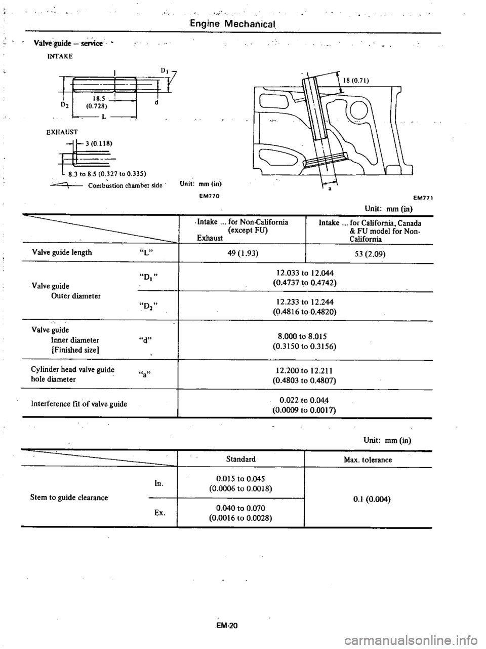
guide
senice
INTAKE
f
D21
Dl
I
r
I
I
I
d
18
5
0
728
L
EXHAUST
II
3
0
118
t
81
o
8
5
327
to
0
335
Combustion
chamber
ide
Valve
guide
length
L
D
Valve
guide
Outer
diameter
D2
Valve
guide
Inner
diameter
Finished
size
d
Cylinder
head
valve
guide
hole
diameter
a
Interference
fit
of
valve
guide
In
Stem
to
guide
clearance
Ex
Engine
Mechanical
1
Unit
mm
in
EM770
Intake
for
Non
California
except
FU
Exhaust
49
1
93
EM171
Unit
mm
in
Intake
for
California
Canada
FU
model
for
Non
California
53
2
09
12
0331012
044
0
4737
to
0
4742
12
233
to
12
244
0
4816
to
0
4820
8
000
to
8
015
0
3150
to
0
3156
12
200
to
12
211
0
4803
to
0
4807
0
022
to
0
044
0
0009
to
0
0017
Standard
0
Q15
to
0
045
0
0006
to
0
0018
0
040
to
0
070
0
0016
to
0
0028
EM
20
Unit
mm
in
Max
tolerance
0
1
0
004
Page 64 of 548
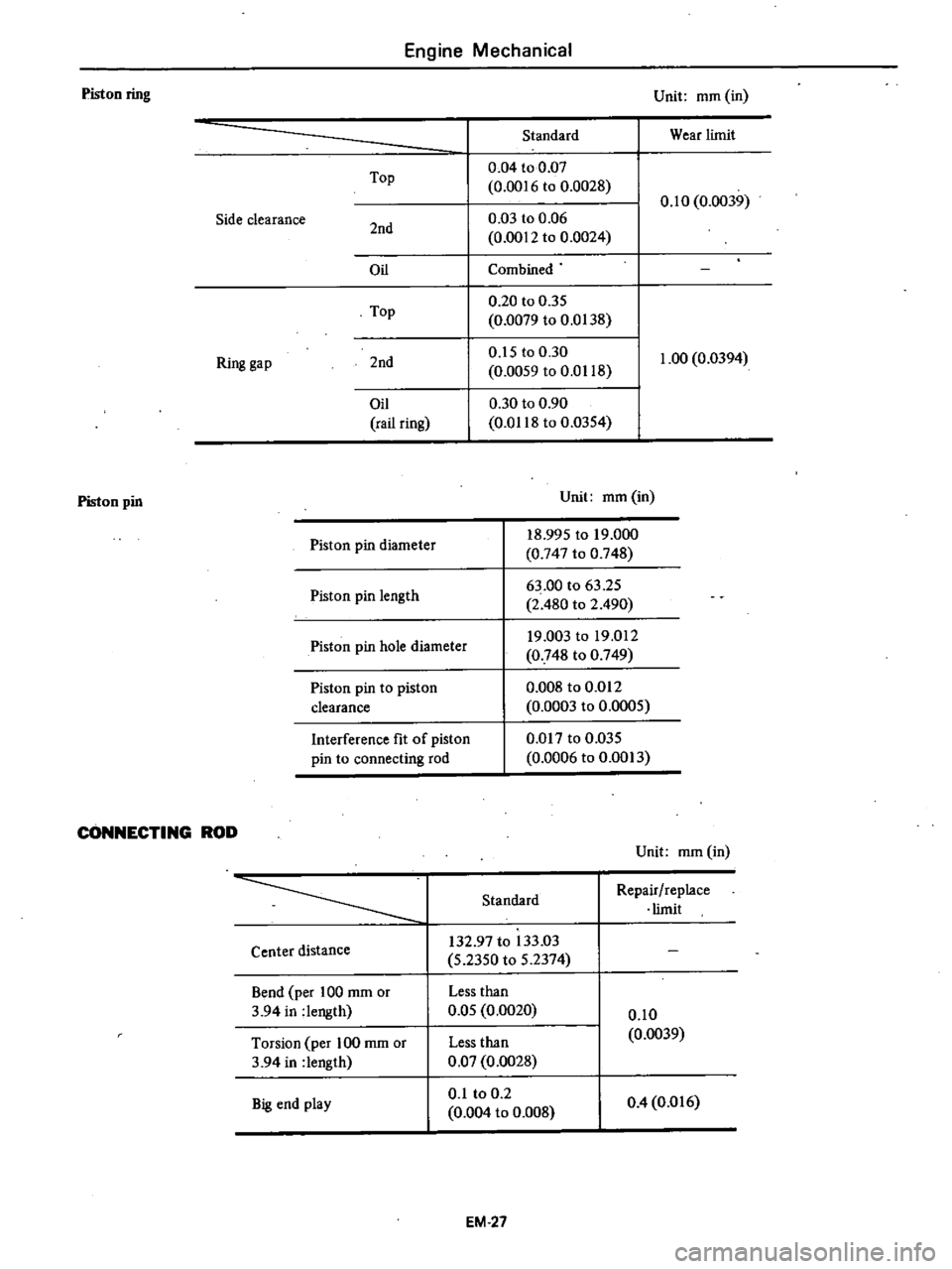
Engine
Mechanical
Piston
ring
Unit
mm
in
Standard
Wear
limit
Top
0
04
to
0
07
0
0016
to
0
0028
0
10
0
0039
Side
clearance
2nd
0
03
to
0
06
0
0012
to
0
0024
Oil
Combined
Top
0
20
to
0
35
0
0079
to
0
0138
Ring
gap
2nd
0
15
to
0
30
1
00
0
0394
0
0059
to
0
0118
Oil
0
30
to
0
90
rail
ring
0
0118
to
0
0354
Piston
pin
Unit
mm
in
Interference
fit
of
piston
pin
to
connecting
rod
18
995
to
19
000
0
747
to
0
748
63
00
to
63
25
2
480
to
2
490
19
003
to
19
012
0
748
to
0
749
0
008
to
0
012
0
0003
to
0
0005
0
017
to
0
035
0
0006
to
0
0013
Piston
pin
diameter
Piston
pin
length
Piston
pin
hole
diameter
Piston
pin
to
piston
clearance
CONNECTING
ROD
Unit
mm
in
Standard
Repair
replace
limit
Center
distance
132
97
to
133
03
5
2350
to
5
2374
Bend
per
100
mm
or
3
94
in
length
Less
than
0
05
0
0020
0
10
0
0039
Torsion
per
100
mm
or
3
94
in
length
Big
end
play
Less
than
0
07
0
0028
0
1
to
0
2
0
004
to
0
008
0
4
0
016
EM
27
Page 76 of 548
Not
Pump
rotors
and
body
are
not
serv
iced
separatdy
If
pump
rotors
or
body
are
damaged
or
worn
replace
ment
of
the
entire
oil
pump
assembly
isnecessary
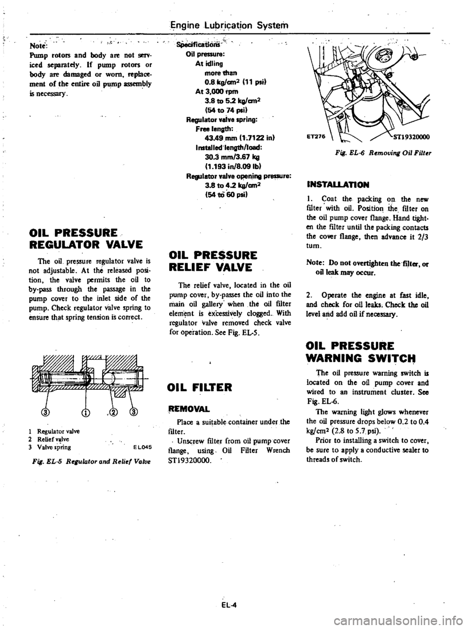
OIL
PRESSURE
REGULATOR
VALVE
The
oil
pressure
regulator
valve
is
not
adjustable
At
the
released
posi
tion
the
valve
permits
the
oil
to
by
pass
through
the
passage
in
the
pump
cover
to
the
inlet
side
of
the
pump
Check
regulator
valve
spring
to
ensure
that
spring
tension
is
correct
no
1
Regulator
valve
2
Relief
valve
3
Valve
spring
E
L045
Fig
EL
5
Regulator
and
Reli
Vatv
Engine
Lubrication
System
8Peciflcatlons
Oil
pressure
At
idling
more
than
O
Blrg
an2
11
psi
At
3
000
rpm
3
B
to
5
2lrg
an2
54
to
74
psi
Regulator
ai
spring
Free
length
43
49
rom
1
7122
in
InstoJlod
l
ngth
load
30
3
mm
3
67
kg
1
193
inJB
09lbl
Regulator
val
o
ning
pressur
3
8
to
4
2
lrg
an2
54
1060
psi
OIL
PRESSURE
RELIEF
VALVE
The
relief
valve
located
in
the
oil
pump
cover
by
passes
the
oil
into
the
main
oil
gallery
when
the
oil
filter
elem
nt
is
exCessively
clogged
With
regula
tor
valve
removed
check
valve
for
operation
See
Fig
EL
5
OIL
FILTER
tEMOVAL
Place
a
suitable
container
under
the
f1lter
Unscrew
f1lter
from
oil
pump
cover
flange
using
Oil
Filter
Wrench
STl9320000
EL
4
Fig
EL
6
Removing
Oil
Filter
INSTALLAnON
I
Coat
the
packing
on
the
new
f1lter
with
oil
Position
the
f1lter
on
the
oil
pump
cover
flange
Hand
tight
en
the
f11ter
until
the
packing
contacts
the
cover
flange
then
advance
it
2
3
tum
Note
Do
not
overtighten
the
fiIter
or
oil
leak
may
occur
2
Operate
the
engine
at
fast
idle
and
check
for
oil
leaks
Check
the
oil
level
and
add
oil
if
necessary
OIL
PRESSURE
WARNING
SWITCIt
The
oil
pressure
warning
switch
is
located
on
the
oil
pump
cover
and
wired
to
an
instrument
cluster
See
Fig
EL
6
The
warning
light
glows
whenever
the
oil
pressure
drops
below
0
2
to
0
4
kg
cm1
2
8
to
5
7
psi
Prior
to
installing
a
switch
to
cover
I
be
sure
to
apply
a
conductive
sealer
to
threads
of
switch
Page 77 of 548

Engine
Lubrication
System
SERVICE
DATA
AND
SPECIFICATIONS
Oil
pump
Standard
Wear
limit
Rotor
side
clearance
nun
in
0
04
to
0
08
0
20
0
0079
Rotor
to
bottom
cover
0
0016
to
0
0031
Rotor
tip
clearance
mm
in
less
than
0
20
0
0079
0
12
0
0047
Outer
rotor
to
body
clearance
nun
in
0
15
to
0
21
0
50
0
0197
0
0059
to
0
0083
Oil
pressure
regulator
valve
Oil
pressure
a
t
idling
Oil
pressure
at
3
000
rpm
Regulator
valve
spring
Free
length
Installed
length
load
kg
cm2
psi
kg
cm2
psi
more
than
0
8
II
3
8
to
5
2
54
to
74
nun
in
nun
kg
in
lb
43
49
I
7122
30
3
3
67
1
193
8
09
Tightening
torque
Oil
pump
securing
bolts
Oil
pump
cover
bolt
Regulator
valve
cap
nut
kg
m
ft
lb
kg
m
ft
lb
kg
m
ft
lb
0
9
to
I
4
6
5
to
10
1
0
39
to
0
52
2
8
to
3
8
4
0
to
5
0
29
to
36
TROUBLE
DIAGNOSES
AND
CORRECTIONS
Condition
Probable
cause
Corrective
action
Oil
leakage
Damaged
or
cracked
body
cover
Oil
leakage
from
gasket
Oil
leakage
from
regulator
valve
Oil
leakage
from
blind
plug
Replace
Replace
Tighten
or
replace
Replace
Decreased
oil
pressure
Leak
of
oil
in
engine
oil
pan
Dirty
oil
strainer
Damaged
or
worn
pump
rotors
Faulty
regulator
Used
of
poor
quality
engine
oil
Correct
Clean
or
replace
Replace
Adjust
or
replace
Replace
Noise
Excessive
backlash
in
pump
rotors
Replace
EL
5
Page 165 of 548
TERMINAL
Check
terminal
for
damage
and
wear
and
replace
magnetic
switch
assembly
if
necessary
FIELD
COIL
Check
field
coil
for
insulation
If
the
insulation
of
oil
is
damaged
or
worn
it
should
be
replaced
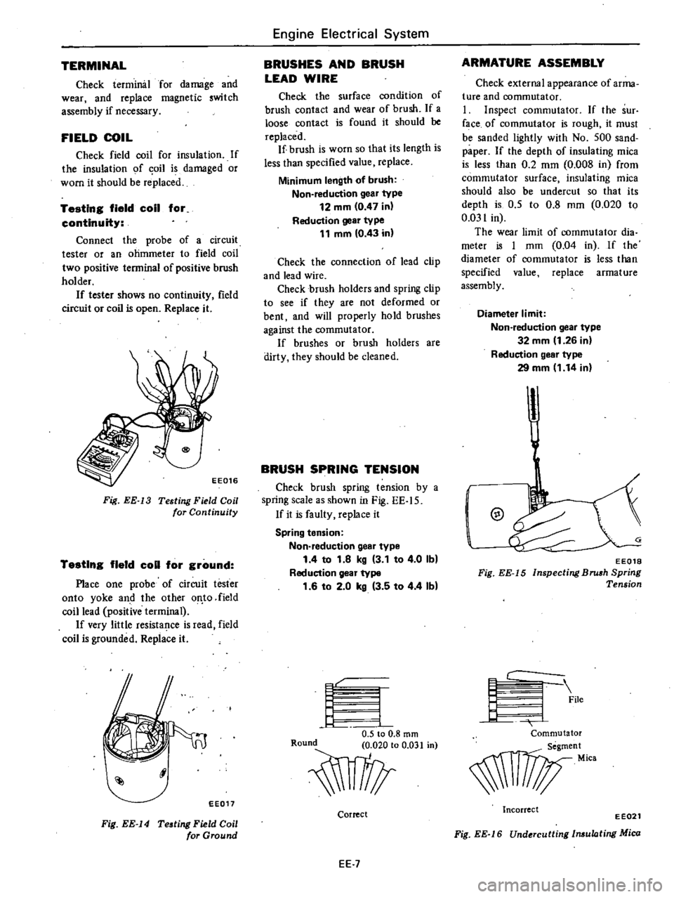
Testing
field
coil
for
continuity
Connect
the
probe
of
a
circuit
tester
or
an
ohmmeter
to
field
coil
two
positive
terminal
of
positive
brush
holder
If
tester
shows
no
continuity
field
circuit
or
coil
is
open
Replace
it
Fig
EE
13
Testing
Field
Coil
for
Continuity
Testing
field
coli
for
ground
Place
one
probe
of
circuit
tester
onto
yoke
and
the
other
of
to
field
coil
lead
positive
terminal
If
very
little
resistance
is
read
field
coil
is
grounded
Replace
it
I
EE017
Fig
EE
14
Testing
Field
Coil
for
Ground
Engine
Electrical
System
BRUSHES
AND
BRUSH
LEAD
WIRE
Check
the
surface
condition
of
brush
contact
and
wear
of
brush
If
a
loose
contact
is
found
it
should
be
replaced
If
brush
is
worn
so
that
its
length
is
less
than
specified
value
replace
Minimum
length
of
brush
Non
reduction
gear
type
12
mm
0
47
in
Reduction
gear
type
11
mm
0
43
in
Check
the
connection
of
lead
clip
and
lead
wire
Check
brush
holders
and
spring
clip
to
see
if
they
are
not
deformed
or
bent
and
will
properly
hold
brushes
against
the
commutator
If
brushes
or
brush
holders
are
dirty
they
should
be
cleaned
BRUSH
SPRING
TENSION
Check
brush
spring
tension
by
a
spring
scale
as
shown
in
Fig
EE
l
5
If
it
is
faulty
replace
it
Spring
tension
Non
reduction
geaf
type
1
4
to
1
8
kg
3
1
to
4
0
Ib
Reduction
gear
type
1
6
to
2
0
kg
3
5
to
4
4
Ib
I
r
4
1
0
5
to
0
8
rom
O
iO
Correct
EE
7
ARMATURE
ASSEMBLY
Check
external
appearance
of
arma
ture
and
oommutator
I
Inspect
commutator
If
the
sur
face
of
commutator
is
rough
it
must
be
sanded
lightly
with
No
500
sand
paper
If
the
depth
of
insulating
mica
is
less
than
0
2
mm
0
008
in
from
commutator
surface
insulating
mica
should
also
be
undercut
so
that
its
depth
is
0
5
to
0
8
mm
0
020
to
0
031
in
The
wear
limit
of
commutator
dia
meter
is
I
mm
0
04
in
If
the
diameter
of
commutator
is
less
than
specified
value
replace
armature
assembly
Diameter
limit
Non
reduction
gear
type
32
mm
1
26
in
Reduction
gear
type
29
mm
1
14
in
I
@
EE018
Fig
EE
15
Inspecting
Bnah
Spring
Tension
c
I
File
Commutator
nt
I
1
11
Mica
Incorrect
EE021
Fig
EE
16
Undercutting
Imulating
Mica
Page 190 of 548

Engine
Electrical
System
STARTING
MOTOR
Type
S1I4
160B
I
Sl14
163E
S114
253
Outer
diameter
of
commutator
mm
in
More
than
32
1
26
More
than
29
L14
Minimum
length
of
brush
mm
in
12
0
47
II
0
43
Brush
spring
tension
kg
Ib
1
4
to
1
8
3
1
to
4
0
1
6to
2
0
3
5
to
4
4
Clearance
between
bearing
metal
and
armature
shaft
mm
in
Less
than
0
2
0
008
Clearance
R
between
pinion
front
edge
and
pinioIl
stopper
mm
in
0
3
to
2
5
0
012
to
0
098
Difference
T
in
height
of
pinion
nun
in
0
3
to
1
5
0
012
to
0
059
ALTERNATOR
Type
LRI5049
Minimum
length
of
brush
mm
in
More
than
7
5
0
295
Brush
spring
pressure
gr
oz
255
to
345
8
99
to
12
17
Slip
ring
outer
diameter
nun
in
More
than
30
1
18
DISTRIBUTOR
Air
gap
mm
in
D4K8
19
I
D4K8
l3
I
D4K8
18
I
D4K8
02
D4K8
15
I
D4K8
16
0
3
to
0
5
0
012
to
0
020
Type
Cap
il1s
ation
resistance
M
1
More
than
50
Rotor
head
insulation
resistance
Mil
More
than
50
Cap
carbon
point
length
mm
in
10
0
39
Vacuum
advance
0
105
4
13
0
170
6
69
0
80
3
15
0
105
4
13
0
70
2
76
0
170
6
69
Distributor
degree
distributor
9
250
3
225
12
265
9
300
15
300
6
5
300
mmHg
inHg
9
84
8
86
10
43
11
81
11
81
11
81
Centrifugal
advance
0
550
6
550
0
550
0
550
0
750
0
750
Distributor
degree
distributor
14
2
300
14
2
300
13
5
2
400
13
5
2
400
10
2
400
10
2
400
rpm
EE
32
Page 195 of 548

Engine
Electrical
System
IV
IGNITION
CIRCUIT
When
engine
does
not
start
If
there
is
no
problem
in
fuel
system
ignition
system
should
be
checked
This
can
be
easily
done
by
detaching
a
high
tension
cable
from
distributor
starting
engine
and
ob
serving
oondition
of
spark
that
occurs
between
high
tension
cable
and
engine
block
After
checking
this
repair
as
necessary
tery
and
anti
dieseliilg
wlenoid
valve
connector
to
cuI
off
supply
of
fuel
10
engine
Then
observe
the
condition
of
sparks
while
starter
motor
is
in
operation
Note
Turn
ignilion
switch
off
and
disconnect
ground
cable
from
bat
Condition
Location
Probable
cause
Corrective
action
No
spark
at
all
Distributor
Breakage
of
lead
wire
on
low
tension
side
Repair
Poor
insulation
of
cap
and
rotor
head
Replace
Open
pick
up
coil
Replace
Air
gap
wider
than
specification
Adjust
Ignition
coil
Wire
breakage
or
short
circuit
of
coil
Replace
with
new
one
High
tension
cable
Wire
coming
off
Repair
Faulty
insulation
Replace
IC
ignition
unit
Faulty
IC
ignition
unit
Replace
Breakage
of
circuit
Replace
Detached
connection
Repair
Spark
length
Spark
plugs
Spark
plug
gap
too
wide
Correct
or
replace
More
than
6
mm
Too
much
carbon
Clean
or
replace
0
24
in
Broken
neck
of
insulator
Replace
Expiration
of
plug
life
Replace
Distributor
Air
gap
too
wide
Correct
IC
ignition
unit
Faulty
IC
ignition
unit
Replace
Breakage
of
circuit
Replace
Detached
connection
Repair
EE
37