lock DATSUN 210 1979 Service Manual
[x] Cancel search | Manufacturer: DATSUN, Model Year: 1979, Model line: 210, Model: DATSUN 210 1979Pages: 548, PDF Size: 28.66 MB
Page 489 of 548
cIo
CD
m
t
tl
3
Cl
4
Ii
ii
C
l
I
i
I
ll
g
toom
a
ll
CALIFORNIA
ANO
BATTERY
FU
MOOELS
R
G
ff
w
G
M
wr
N
Q
WR
ALTERNATOR
ANO
IC
NON
cALIFOR
IA
VOLTAGE
REGULATOR
ANO
CANAOA
MO
S
I
fh
WR
B
i
W
i
C
@
J
W
l
9
i
j
@
Q
B
LB
OIL
PRESSURE
SWITCH
0
I
I
l
lOCI
OfflACC
OH
SI
Ys
j
D
01
mQ
IS
i
I
l
I
s
II
10
J
J
SWITCH
IGNITION
iji
BY
wr
1
I
1
IW
BRAKE
FLUIO
LEVEL
SWITCH
Ot
o
BJ
JO
0
Y
l
I
AUTO
cHOKE
RELAY
V
I
r
I
MAIN
HARNESS
FUSE
BLOCK
0
0
lOA
cr
L
lOA
cr
G
1
r
L
BL
HANO
BRAKE
SWITCH
G
J
i
INSTRUMENT
HARN
ESS
fG
YG
10
OMB
N
AT
qN
ETER
o
BRAKE
0
WARNING
LAMP
100
G
O
00
3
YB
f
G
WR
J
I
0
1
Fo
o
e
i
1
z
YB
OIL
PRESSURE
WARNING
LAMP
J
lI
a
Ill
z
11
1
III
Z
G
Ill
11
1
Ut
0
iUt
Ill
alii
11
1
I
a
i
l
i
Ill
Z
i
a
X
OJ
o
Cl
m
CD
o
CIl
l
3
Page 490 of 548

m
l
U1
ii
I
ll
cio
i
t
s
a
Cl
t
m
l
e
BATTERY
8
GtG
ug
ew
FUSIBLE
LINK
BELT
TIMER
I
i
DD
l
J
G
if
I
lOCI
OffIACCI
aNI
Sf
I
0
0
8
i
i
16
I
S
IGNITION
SWITCH
FUSE
BLOCK
B
0
lOA
G
L
BL
ORIVER
S
BELT
SWITCH
tl
WARNING
LAMP
iP
aB
ij
II
VB
L
I
81
WB
I
t
OI
00
00
0
0
B
B
B
B
feB
WARNING
BUZZER
III
e
IIll
a
I
III
Z
i
C
OJ
o
Cl
m
CD
n
o
Q
CIl
en
l
3
Page 493 of 548

m
J
Co
5
oil
tl
Cl
s
5
Q
0
0
WAS
ER
MOTOR
t
l
I
o
BATTERY
A
G
ll
J
wr
FUSIB
E
LINK
Off
UN
HI
WASH
11
J
BY
9
n
13
4d
1
o
14
J
I
Q
I
16
m
LW
2
0
u
J
WIPER
ANO
WASHER
SWITCH
I
lGCK
OfF
ACe
OM
Sf
2
0
OnOOB
m
iL
IG
i
I
0
S
00
A
II
WR
LB
IGNITION
SWITCH
Off
ON
WASHV
iW
REAR
WIPER
0
0
11
l
R
SWITCH
I
0
Q
I
2
I
B
HATCHBACK
0
I
I
3
o
II
LR
n
I
I
III
I
I
1
I
1
iI
Y
WIPER
MOTOR
LR
ti
BY
B
R
r
REAR
WASHER
MOTOR
IHATCHBACK
ANO
i
WAGON
Em
I
m
IIIn
zoot
a
11
1
I
a
E
lI
11
1
a
n
Jon
ZII
aen
i
III
a
io
OJ
a
It
8
0
It
m
l
l
In
l
CIl
l
3
HATCHBACK
LR
BOOYHARNESS
z
I
L
I
OO
B
iOl
c
TO
REAR
OEFOGGER
I
LR
rLB
1
I
3
0
i
BW
R
LRh
ftn
WAGON
0
0
r
o
REAR
WIPER
MOTOR
CRWl
T1
c
l
Rlif
1
I
mC
BilW
lJ
I
g
LR
Jj
i
1
FUSE
BLOCK
Page 494 of 548
Body
Electrical
System
HORN
CIGARETTE
LIGHTER
AND
CLOCK
SYSTEM
I
I
0
W
l
I
fD
CCI
MAIN
HARNESS
I
I
0
en
srb
J
I
U
h
E
0
0
z
t
LL
Z
U
J
w
z
on
QlJ
J
w
0
Y
X
o
I
CIGARETTE
LIGHTER
Itt
9
J
J
I
Z
w
en
l
o
z
1
0
en
Zrl
I
O
tEl
g
r
J
i
I
J
al
I
J
ti
J
ti
1
1
J
J
8ho
f
J1
tf
J
P
II
J
J
1
I
I
e
o
TURN
SIGNAL
SWITCH
CLOCK
01
0
I
J
u
o
J
W
en
u
9W
tutJ
I
j
I
6
I
r
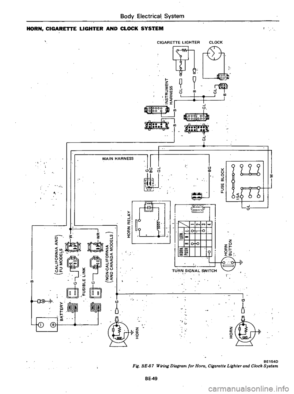
BE154D
Fig
BE
87
Wiring
Diagram
for
Horn
Cigarette
Lighter
and
Clock
System
BE49
Page 495 of 548

m
ii
lil
cIo
00
tl
i
3
Cl
0
m
0
g
fB
Jo
0
0
Ef1
CALIFORNIA
ANO
FU
MOOELS
t
f
G
W
g
dG
I
WR
FUSIBLE
LINK
8
G
uQ
t
WR
NON
cALIFORNIA
AND
CANAOA
MOOELS
J
TORQUE
CONVERTER
C
ao
GY
INOICATOR
LAMP
5
l
1
00
GW
I
BATTERY
CCOHST7
i
lOCK
Off
A
B
OO
C
I
ti
II
v
u
1
WITCH
IGNITION
S
2ND
Oil
lS1
B
C
C
AI8
C
I
5
A
8
I
QIQ
Q
Q
J1
0
0
I
0
6
B
6
0
7
Q
QIQIQ
8
0
0
0
9
O
I
LIGHTING
SWITCH
Z
1
D
Z
m
en
WR
LB
1lRG
GW
INSTRUMENT
HARNESS
j
lO
GW
I
oGW
GY
00
GY
LW
LW
I@o
00
og
B
0
u
B
LW
LB
I
I
0
0
J8
RG
w
1
0
r
O
FUSE
BLOCK
LW
ClO
LW
W
t
WB
1
r
GY
GW
RAOIO
ffi
i
n
In
U
L
J
UJ
J
U
WB
O
W
SPEAKER
OJ
o
Cl
m
CD
C
e
CIl
en
3
Page 496 of 548

m
ii
Co
0
i
tl
c
Cl
0
c
o
E
0
Cl
l
l
n
m
iO
t
B
i
BATTERY
A
G
FUSIBLE
LINK
I
I
lOCK
OfF
ACC
ON
S17
o
O
6
16
0
s
l
O
J
IA
IGN
ITION
SWITCH
FUSE
BLOCK
0
3
C
rT
l
WR
Q
BW
WR
I
BL
Z
J
Z
m
en
en
LG
l
LG
BOOY
HARNESS
6
J
1
nUl
I
OEFOGGER
l
C
ISEOAN
M
1R2
106
00
n
03
INSTRUMENT
B
I
II
8
HARNESS
f
i
G
0rF
to
LB
1
2
6
0
3
0
0
0
gg
REAR
WINOOW
OEFOGGER
SWITCH
l
0
II
11
1
Jo
II
E
z
a
11
1
II
o
8
11
1
II
OJ
o
Cl
m
CD
c
Ql
CIl
en
l
3
Page 497 of 548
Body
Electrical
System
THEFT
CTlON
SYSTEM
t
o
CALIFORNIA
ANO
BATTERY
FU
MOOELS
G
t
WT
FUSIBGLE
LINK
I
at
L
Q
Q
WRJ
NON
cALlFORNIA
ANO
CANAOA
MOOELS
WARNING
BUZZER
STEERING
n
LOCK
u
SWITCH
U
D
7
RC
JQ
RL
2
2
00
i
r
B
Le
r
RljG
8
RG
FUSE
BLOCK
0
RLel
L
OOOR
ITCH
R
CJ
E
W
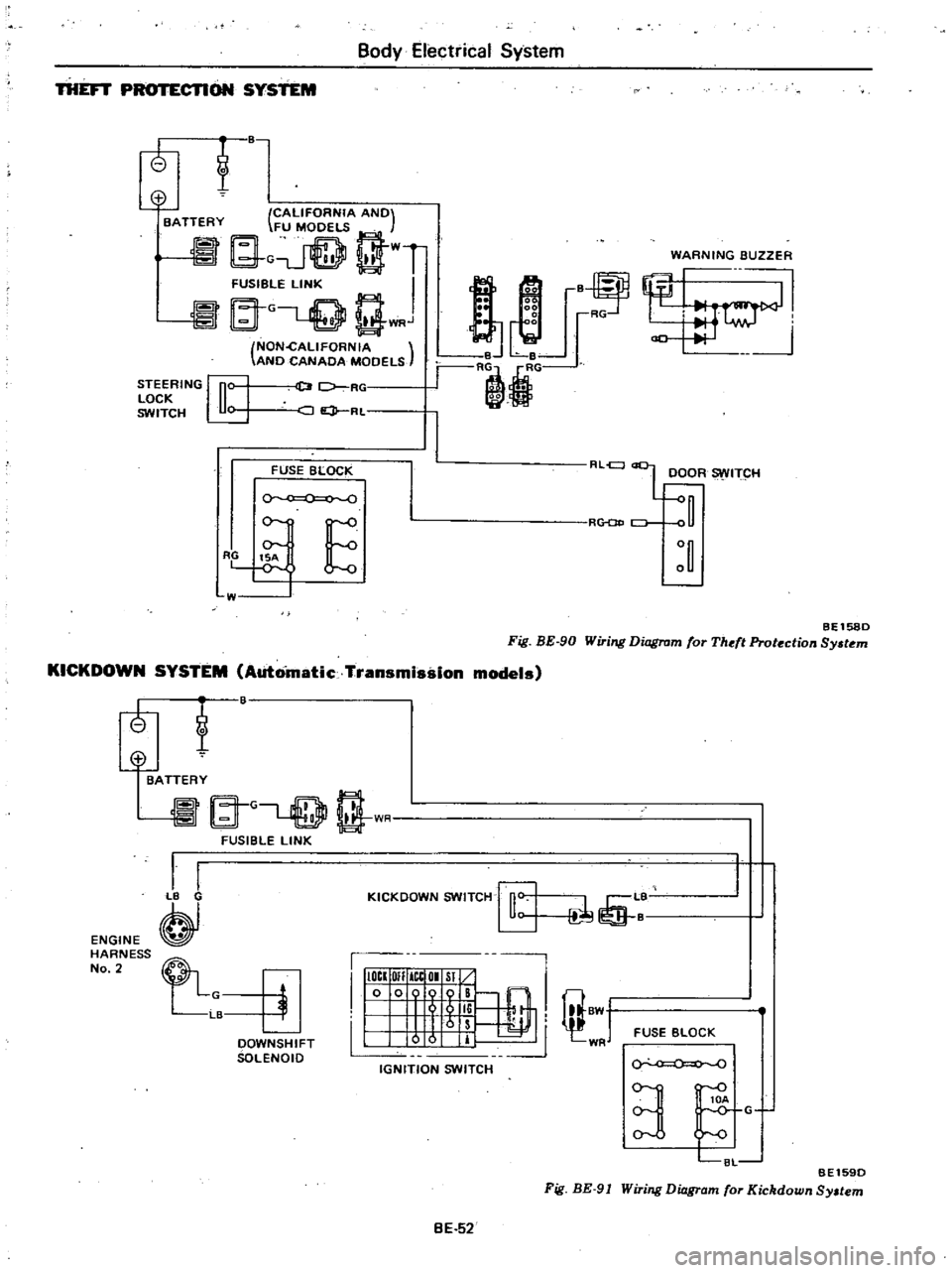
BEl580
Fig
BE
90
Wiring
Diagram
for
Theft
Protection
Sy
tem
KICKDOWN
SYSTEM
Automatic
Transmission
models
tf
ENGINE
HARNESS
No
2
@
BATTERY
A
G
rT
l
t
1
I
FUSIBLE
LINK
I
I
B
KICKOOWN
SWITCH
rfi
L
1
I
IIIOCI
OIl
ICtOI
Sl
10
009
B
@
I
I
5
li
I
8W
1
Irs
I
0
0
IT
WR
IGNITION
SWITCH
FUSE
BLOCK
OOWNSHIFT
SOLENOIO
0
0
BE1590
Fig
BE
91
Wiring
Diagram
for
Kickdown
Sy
tem
3
C8L
G
BE
52
Page 500 of 548

m
ii
I
ll
ic
i
tl
Cl
Ul
0
is
B
w
ii
W
oa
LW
L
CALIFORNIA
ANO
I
d
S
R
FUSIBLE
LINK
o
BATTERY
S
JSt
wGLQ
gWR
NON
GALIFORNIA
ANO
CANAOA
MOOELS
LOC
Off
Ace
ON
Sf
o
0
i
IGNITION
SWITCH
L
B
LN
I
15A
0
0
0
0
o
v
E
FUSE
BLOCK
M
F
i
L
11L1
u
R
1
i
ri
1
w
RESISTOR
BW
Il
BLj
L
lljlj
U6
1
BWY
W
B
8
HEAVY
OUTY
TYPE
Standard
for
Canada
and
option
for
U
S
A
LW
HEATER
MOtOR
IOffl
I
2
3
Kro
lli
H
FAN
SWITCH
ST
ANOARO
TYPE
Z
II
II
a
OJ
o
Cl
m
CD
n
n
Ql
CIl
CJ
l
3
Page 507 of 548
VACUUM
SYSTEM
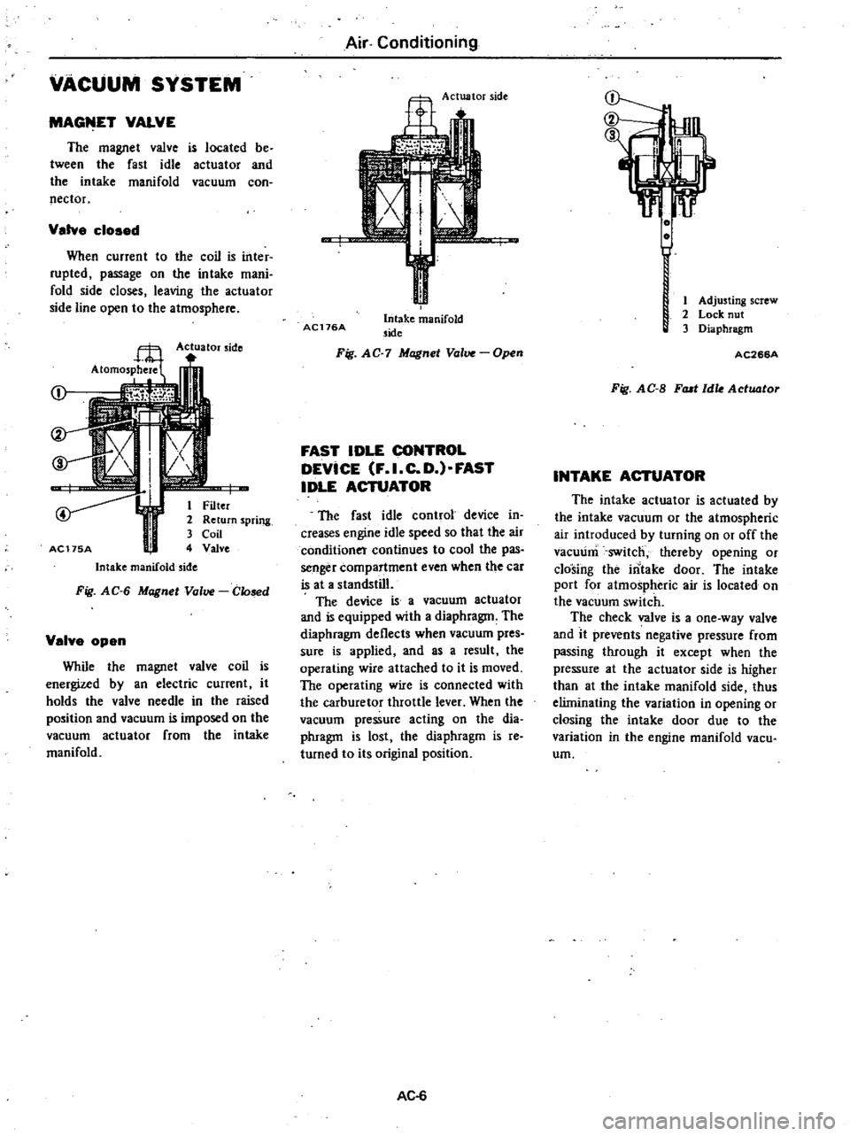
MAGfilET
VALVE
The
magnet
valve
is
located
be
tween
the
fast
idle
actuator
and
the
intake
manifold
vacuum
con
nector
Valve
cloaed
When
current
to
the
coil
is
inter
rupted
passage
on
the
intake
mani
fold
side
closes
leaving
the
actuator
side
line
open
to
the
atmosphere
Actuator
side
j
I
i
r
1
Filter
2
Return
spring
3
Coil
AC175A
4
Valve
Intake
manifold
side
Fig
AG
6
Magnet
Valve
Glosed
Velve
open
While
the
magnet
valve
coil
is
energized
by
an
electric
current
it
holds
the
valve
needle
in
the
raised
position
and
vacuum
is
imposed
on
the
vacuum
actuator
from
the
intake
manifold
Air
Conditioning
Actuator
side
AC176A
Intake
manifold
side
Fig
AG
7
Magnet
Valve
Open
FAST
IDLE
CONTROL
DEVICE
F
I
C
D
FAST
IDLE
ACTUATOR
The
fast
idle
control
device
in
creases
engine
idle
speed
so
that
the
air
conditioner
continues
to
cool
the
pas
senger
compartment
even
when
the
car
is
at
a
standstill
The
device
is
a
vacuum
actuator
and
is
equipped
with
a
diaphragm
The
diaphragm
deflects
when
vacuum
pres
sure
is
applied
and
as
a
result
the
operating
wire
attached
to
it
is
moved
The
operating
wire
is
connected
with
the
carburetor
throttle
lever
When
the
vacuum
pressure
acting
on
the
dia
phragm
is
lost
the
diaphragm
is
reo
turned
to
its
original
position
AC
6
1
Adjusting
screw
2
Lock
nut
3
Diaphragm
AC266A
Fig
AG
B
FlUI
Idle
Actuator
INTAKE
ACTUATOR
The
intake
actuator
is
actuated
by
the
intake
vacuum
or
the
atmospheric
air
introduced
by
turning
on
or
off
the
vacuum
switch
thereby
opening
or
closing
the
intake
door
The
intake
port
for
atmospheric
air
is
located
on
the
vacuum
switch
The
check
valve
is
a
one
way
valve
and
it
prevents
negative
pressure
from
passing
through
it
except
when
the
pressure
at
the
actuator
side
is
higher
than
at
the
intake
manifold
side
thus
eliminating
the
variation
in
opening
or
closing
the
intake
door
due
to
the
variation
in
the
engine
manifold
vacu
urn
Page 511 of 548
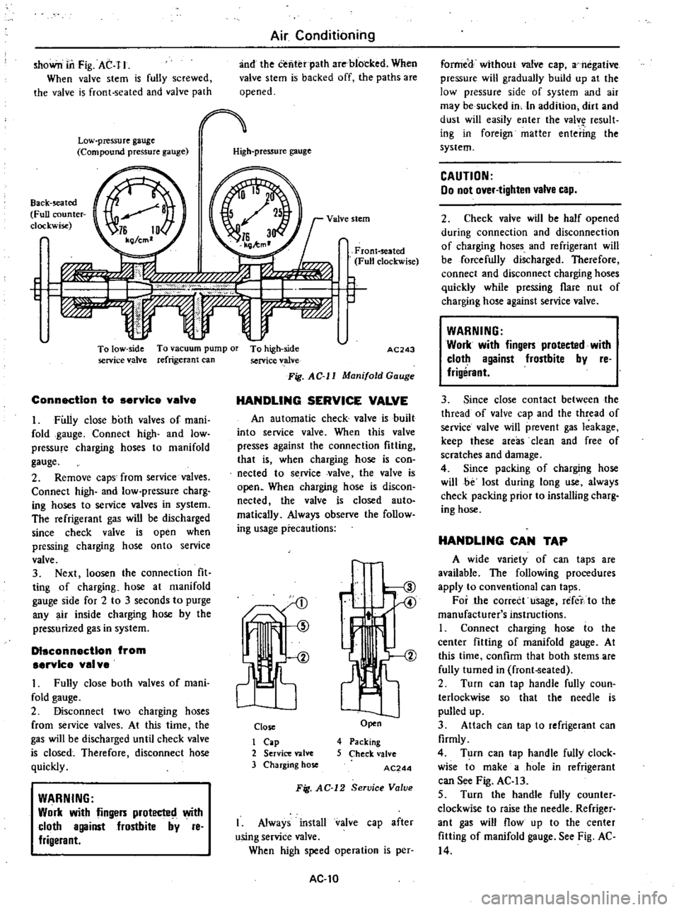
shoWn
in
Fig
AC
I
I
When
valve
stem
is
fully
screwed
the
valve
is
front
seated
and
valve
path
Low
pressure
gauge
Compound
pressure
gauge
Air
Conditioning
and
the
tenter
path
are
blocked
When
valve
stem
is
backed
off
the
paths
are
opened
High
pressure
gauge
Back
seated
Full
counter
clockwise
I
VA
l
C
f
f
f
J
l
r
To
low
side
To
vacuum
pump
01
To
high
side
service
valve
refrigerant
can
service
valve
Fig
AC
II
Manifold
Gauge
ConnectIon
to
service
valve
I
Fully
close
both
valves
of
mani
fold
gauge
Connect
high
and
low
pressure
charging
hoses
to
manifold
gauge
2
Remove
caps
from
service
valves
Connect
high
and
low
pressure
charg
ing
hoses
to
service
valves
in
system
The
refrigerant
gas
will
be
discharged
since
check
valve
is
open
when
pressing
charging
hose
onto
service
valve
3
Next
loosen
the
connection
fit
ting
of
charging
hose
at
manifold
gauge
side
for
2
to
3
seconds
to
purge
any
air
inside
charging
hose
by
the
pressurized
gas
in
system
DIsconnection
from
servIce
val
ve
I
Fully
close
both
valves
of
mani
fold
gauge
2
Disconnect
two
charging
hoses
from
service
valves
At
this
time
the
gas
will
be
discharged
until
check
valve
is
closed
Therefore
disconnect
hose
quickly
WARNING
Work
with
fingers
protecte
with
cloth
against
frostbite
by
reo
frigerant
FronHeated
Fun
clockwise
r
AC243
HANDLING
SERVICE
VALVE
An
automatic
check
valve
is
built
into
service
valve
When
this
valve
presses
against
the
connection
fiUing
that
is
when
charging
hose
is
con
nected
to
service
valve
the
valve
is
open
When
charging
hose
is
discon
nected
the
valve
is
closed
auto
matically
Always
observe
the
follow
ing
usage
precautions
1ts
Close
I
Cap
2
Service
valve
3
Charging
hose
ir
Open
4
Packing
5
Check
valve
AC244
Fig
AC
12
Service
Valve
I
Always
install
valve
cap
after
using
service
valve
When
high
speed
operation
is
per
AC
I0
formed
without
valve
cap
a
negative
pressure
will
gradually
build
up
at
the
low
pressure
side
of
system
and
air
may
be
sucked
in
In
addition
dirt
and
dust
will
easily
enter
the
valv
result
ing
in
foreign
matter
entering
the
system
CAUTION
00
not
over
tighten
valve
cap
2
Check
valve
wiJI
be
half
opened
during
connection
and
disconnection
of
charging
hoses
and
refrigerant
will
be
forcefully
discharged
Therefore
connect
and
disconnect
charging
hoses
quickly
while
pressing
flare
nut
of
charging
hose
against
service
valve
WARNING
Work
with
fingers
protected
with
cloth
against
frostbite
by
reo
frigerant
3
Since
close
contact
between
the
thread
of
valve
cap
and
the
thread
of
service
valve
will
prevent
gas
leakage
keep
these
areas
clean
and
free
of
scratches
and
damage
4
Since
packing
of
charging
hose
will
be
lost
during
long
use
always
check
packing
prior
to
installing
charg
ing
hose
HANDLING
CAN
TAP
A
wide
variety
of
can
taps
are
available
The
following
procedures
apply
to
conventional
can
taps
For
the
correct
usage
refet
to
the
manufacturer
s
instructions
I
Connect
charging
hose
to
the
center
fitting
of
manifold
gauge
At
this
time
confirm
that
both
stems
are
fully
turned
in
frontoSeated
2
Turn
can
tap
handle
fully
coun
terlockwise
so
that
the
needle
is
pulled
up
3
Attach
can
tap
to
refrigerant
can
firmly
4
Turn
can
tap
handle
fully
clock
wise
to
make
a
hole
in
refrigerant
can
See
Fig
AC
13
5
Turn
the
handle
fully
counter
clockwise
to
raise
the
needle
Refriger
ant
gas
will
flow
up
to
the
center
fitting
of
manifold
gauge
See
Fig
AC
14