lock DATSUN 210 1979 Service Manual
[x] Cancel search | Manufacturer: DATSUN, Model Year: 1979, Model line: 210, Model: DATSUN 210 1979Pages: 548, PDF Size: 28.66 MB
Page 392 of 548
Specified
rofill
capaeity
GearcaS8
0
28
liter
US
pt
Imp
ptl
Inatallatlon
Install
steering
gear
in
the
reverse
order
of
removal
Observe
the
following
instructions
e
Position
steering
gear
and
rubber
coupling
in
place
then
install
and
Steering
System
tighten
bolts
securing
steering
gear
housing
to
body
side
member
GJ
Tightening
torque
Steering
gear
hou
ing
to
body
id
member
7
0
to
8
0
ku
m
51
to
58
ft
Ibl
Rubber
coupling
to
worm
haft
4
0
to
5
0
kg
m
29
to
36
ft
Ibl
Note
a
Align
the
groove
in
wonn
haft
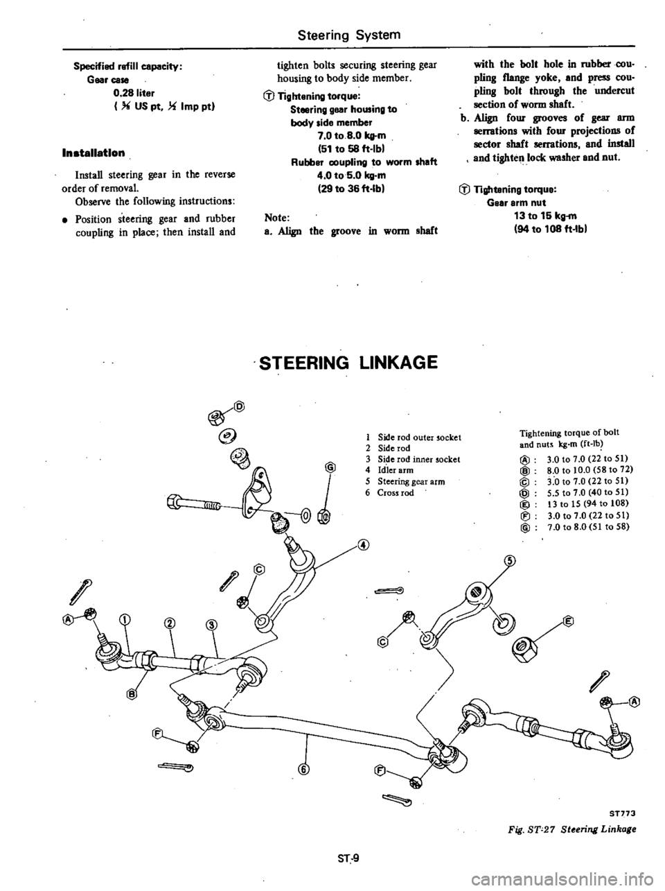
STEERING
LINKAGE
@
@
@
lID
I
O
@
6
1
Side
rod
outer
socket
2
Side
rod
3
Side
rod
inner
socket
4
Id
ler
arm
5
Steering
gear
arm
6
Cross
rod
@
with
the
bolt
hole
in
rubberoou
piing
flange
yoke
and
press
cou
pling
bolt
through
the
undercut
section
of
wonn
sheft
b
Align
four
grooves
of
gear
ann
serrations
with
four
projections
of
sector
haft
serrations
and
install
and
tighten
lock
washer
end
nut
GJ
Tightening
torque
Gelr
arm
nut
13
to
15
kg
m
94
to
108
ft
Ibl
Tightening
torque
afbalt
and
nuts
kg
m
ft
lb
@
3
0
to
7
0
22
to
51
@
8
0
to
10
0
58
to
72
@
3
0
to
7
0
22
to
51
@
5
5
to
7
0
40
to
51
@
13
to
15
94
to
108
Iti
3
0
to
7
0
22
to
51
@
7
0
to
8
0
51
to
58
@
@
@
@
ST
9
ST773
Fig
ST
27
St
ring
Linka
Page 394 of 548
2
Tighten
adjusting
bar
lock
nut
with
cross
and
side
rods
installed
on
car
Note
Lock
adjusting
bar
lock
nut
so
that
ball
joint
on
outer
socket
knuckle
arm
side
is
86019
with
respect
to
that
on
inner
socket
cross
rod
side
INSPECTION
AND
REPAIR
Ball
Joint
1
When
ball
stud
is
worn
or
axial
play
exists
replace
side
rod
socket
with
a
new
one
2
When
dust
cover
is
broken
or
Steering
System
deformed
be
sure
to
replace
with
a
new
one
Initial
turning
torque
Ball
joint
5
to
25
kg
em
4
3
to
21
7
ft
Ibl
Note
Check
idler
side
joint
grease
at
recommended
intervals
and
renew
if
necessary
To
renew
grease
change
screw
with
grease
nipple
and
apply
recommended
grease
to
joint
through
grease
nipple
until
grease
is
forced
out
between
dust
seal
and
joint
socket
Idler
erm
8ssembly
Check
rubber
bushing
of
idler
arm
ST
11
for
breakage
wear
or
play
and
if
necessary
replace
Note
Apply
grease
to
idler
ann
as
sembly
when
disassembled
Cross
rod
and
side
rod
Check
side
rod
and
cross
rod
for
breakage
bend
or
crack
and
replace
with
a
new
one
if
necessary
Fixing
location
Check
fIxing
location
nuts
and
cotter
pins
for
looseness
play
or
breakage
When
looseness
or
play
is
found
check
for
wear
on
tapered
portion
of
ball
stud
gear
arm
or
idler
arm
Page 395 of 548
Steering
System
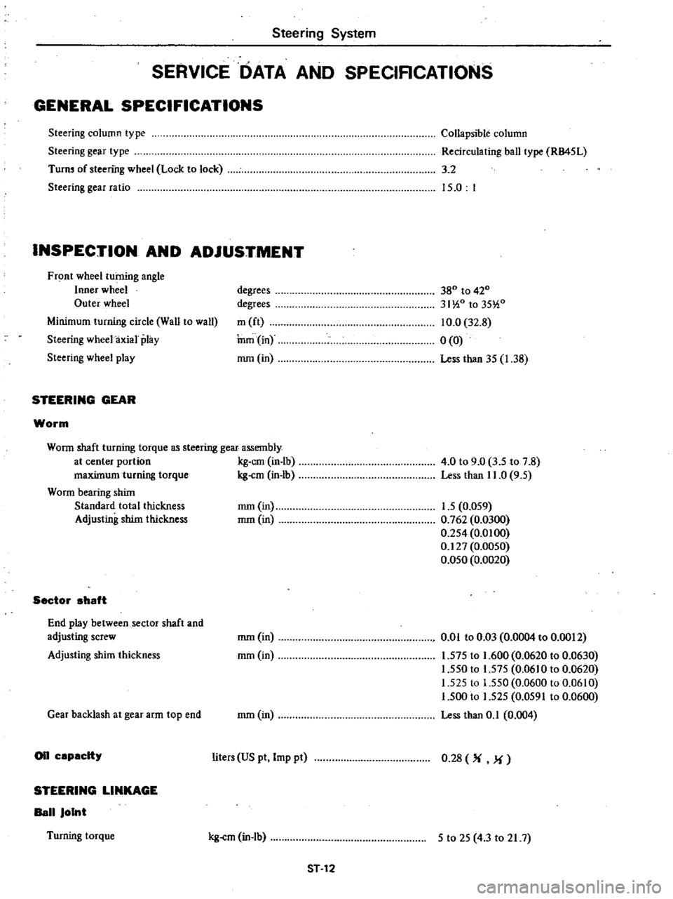
SERVICE
DATA
AND
SPECIRCATIONS
GENERAL
SPECIFICATIONS
Steering
column
type
Steering
gear
type
Turn
of
steering
wheel
Lock
to
lock
Steering
gear
ratio
CollapSIble
column
Recirculating
ball
type
RB45L
3
2
15
0
I
INSPECTION
AND
ADJUSTMENT
Front
wheel
turning
angle
Inner
wheel
Outer
wheel
Minimum
turning
circle
Wall
to
wall
Steering
wheel
axial
play
Steering
wheel
play
STEERING
GEAR
Worm
degrees
degrees
m
ft
nun
in
mm
in
380
to
420
31
i0
to
35
i0
10
0
32
8
0
0
Less
than
35
1
38
Worm
shaft
turning
torque
as
steering
gear
assembly
at
center
portion
kg
em
in
lb
maxUnum
turning
torque
kg
cm
in
lb
Worm
bearing
shUn
Standard
total
thickness
Adjusting
shim
thickness
Sector
ahaft
End
play
between
sector
shaft
and
adjusting
screw
Adjusting
shUn
thickness
Gear
backlash
at
gear
arm
top
end
on
capacity
STEERING
LINKAGE
Ball
Joint
Turning
torque
4
0
to
9
0
3
5
to
7
8
Less
than
11
0
9
5
mm
in
1
5
0
059
mm
in
0
762
0
0300
0
254
0
0100
0
127
0
0050
0
050
0
0020
mm
in
mm
in
om
to
0
Q3
0
0004
to
0
0012
1
575
to
1
600
0
0620
to
0
0630
1
550
to
1
575
0
06
0
to
0
0620
1
525
to
1
550
0
0600
to
0
0610
1
500
to
1
525
0
0591
to
0
0600
Less
than
0
1
0
004
mm
in
liters
US
pt
Imp
pt
0
28
M
kg
cm
in
lb
5
to
25
4
3
to
21
7
ST
12
Page 396 of 548
Steering
System
Side
rod
Standard
side
rod
length
mm
in
315
12
40
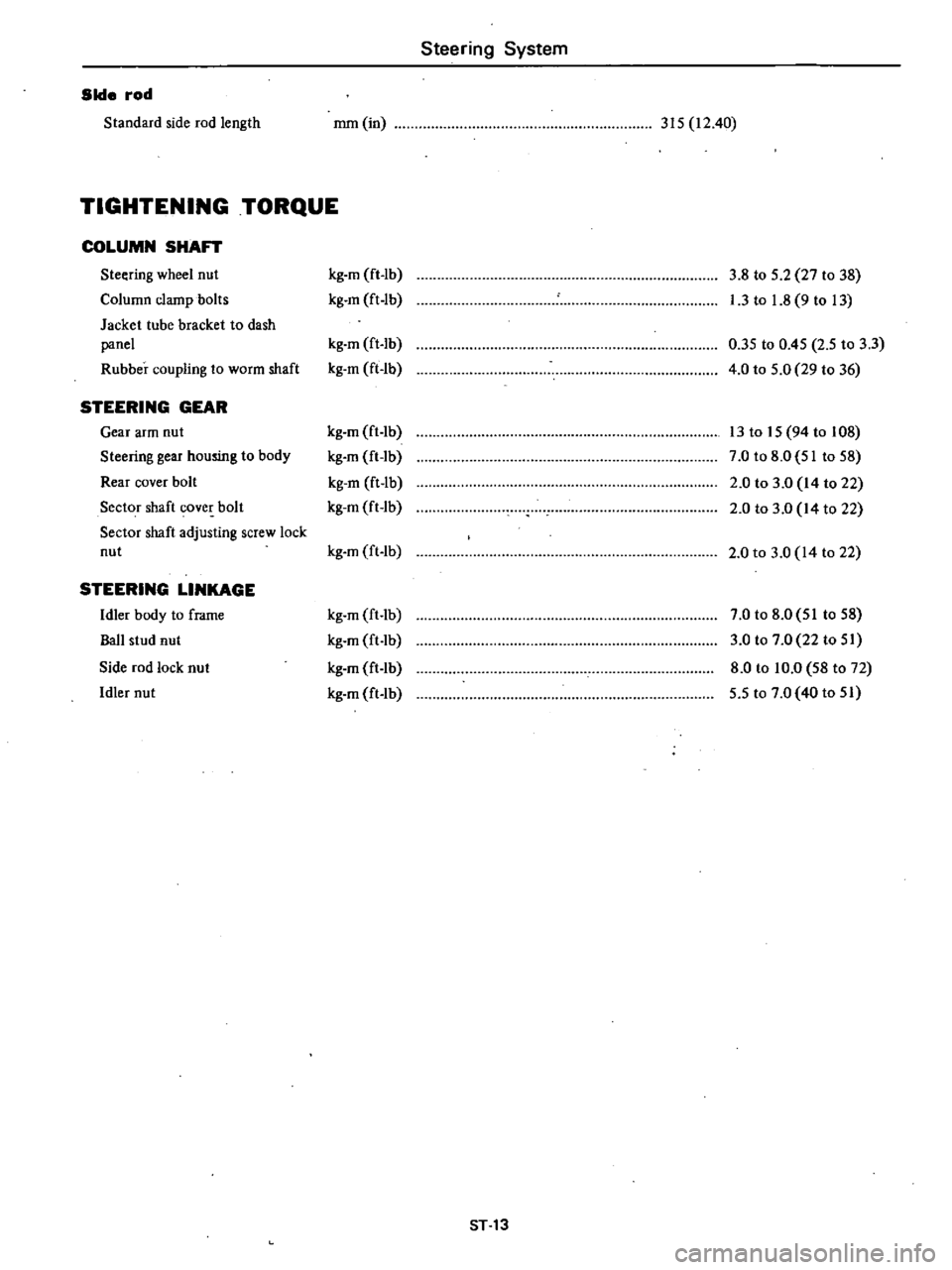
TIGHTENING
TORQUE
COLUMN
SHAFT
Steering
wheel
nut
kg
m
ft
lb
3
8
to
5
2
27
to
38
Column
clamp
bolts
kg
m
ft
lb
I
3
to
1
8
9
to
13
Jacket
tube
bracket
to
dash
panel
kg
m
ft
lb
0
35
to
0
45
2
5
to
3
3
Rubber
coupling
to
worm
shaft
kg
m
ft
lb
4
0
to
5
0
29
to
36
STEERING
GEAR
Gear
arm
nut
kg
m
ft
lb
13
to
15
94
to
108
Steering
gear
housing
to
body
kg
m
ft
lb
7
0
to
8
0
51
to
58
Rear
cover
bolt
kg
m
ft
lb
2
0
to
3
0
14
to
22
Sector
shaft
cover
bolt
kg
m
ft
lb
2
0
to
3
0
14
to
22
Sector
shaft
adjusting
screw
lock
nut
kg
m
ft
lb
2
0
to
3
0
14
to
22
STEERING
LINKAGE
Idler
body
to
frame
kg
m
ft
lb
7
0
to
8
0
51
to
58
Ball
stud
nut
kg
m
ft
lb
3
0
to
7
0
22
to
51
Side
rod
lock
nut
kg
m
ft
lb
8
0
to
10
0
58
to
72
Idler
nut
kg
m
ft
lb
5
5
to
7
0
40
to
51
ST
13
Page 400 of 548
Engine
Control
Fuel
Exhaust
SYlltems
ENGINE
CONTROL
SYSTEM
ACCELERATOR
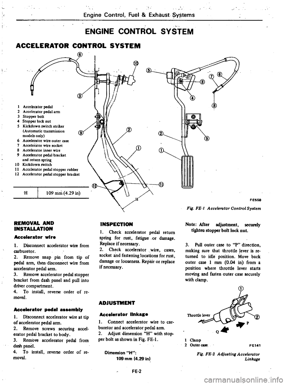
CONTROL
SYSTEM
@
s
1
Acce
i
ator
pedal
2
Accelerator
pedal
arm
3
Stopper
bolt
4
Stopper
lock
nut
S
Kickdown
switch
striker
Automatic
transmission
models
only
6
Accelerator
wire
outer
case
1
Accelerator
wire
socket
8
Accelerator
inner
wire
9
Accelerator
pedal
bracket
and
return
spring
10
Kickdown
switch
11
Accelerator
pedal
stopper
rubber
12
Accelerator
pedal
stopper
bracket
H
109
mm
4
29
in
REMOVAL
AND
INSTALLATION
Accelerator
wI
e
I
Disconnect
accelerator
wire
from
carburetor
2
Remove
snap
pin
from
tip
of
pedal
arm
then
disconnect
wire
from
accelerator
pedal
arm
3
Remove
accelerator
pedal
stopper
bracket
from
dash
panel
and
pull
into
driver
compartment
4
To
install
reverse
order
of
Ie
moval
Accelerator
pedal
a
embly
I
Disconnect
accelerator
wire
at
tip
of
accelerator
pedal
arm
2
Remove
screws
securing
accel
erator
pedal
bracket
to
body
3
Remove
accelerator
pedal
from
dash
panel
4
To
install
reverse
order
of
re
moval
I
IJ
1
II
I
V
J
v
I
@
INSPECTION
I
Check
accelerator
pedal
return
spring
for
rust
fatigue
or
damage
Replace
if
necessary
2
Check
accelerator
wire
cases
socket
and
fastening
locations
for
rust
damage
or
looseness
Repair
or
replace
if
necessary
ADJUSTMENT
Accelerator
IInka
e
I
Connect
accelerator
wire
to
car
buretor
and
accelerator
pedal
arm
2
Adjust
dilnension
H
with
stop
per
bolt
as
shown
in
Fig
FE
I
Dimension
H
109mm
4
29
in
FE
2
F
E558
Fig
FE
I
Accelerator
Control
System
Note
After
adjustment
securely
tighten
stopper
bolt
lock
nut
3
Pull
outer
case
to
uP
direction
making
sure
that
throttle
lever
is
re
turned
to
idle
position
Move
back
outer
case
I
mm
0
04
in
from
a
position
where
throttle
lever
starts
moving
and
fasten
outer
case
securely
with
clamp
Q4t
1
Clamp
2
Outer
case
FE1
1
Fig
FE
2
Adju
ting
Accolerator
Linkage
Page 401 of 548

Engine
Control
Fuel
Exhaust
Systems
4
When
accelerator
pedal
is
fully
depressed
make
sure
that
throttle
valve
opens
fuUy
5
After
above
adjustments
have
been
made
make
sure
that
accelerator
linkage
operates
smoothly
without
dragging
Make
sure
that
throttle
lever
returns
securely
to
idle
position
as
soon
as
accelerator
pedal
is
released
K1ckdown
switch
On
the
automatic
transmission
models
it
is
also
necessary
to
adjust
kickdown
switch
The
kickdown
FE
3
switch
adjustment
is
correct
if
kick
down
switch
is
actuated
by
the
stop
per
located
on
the
tip
end
of
pedal
arm
when
accelerator
pedal
is
de
pressed
fuUy
Always
tighten
lock
nut
securely
when
proper
adjustment
is
obtained
Page 406 of 548
Engine
Control
fuel
Exhaust
Systems
Non
California
models
except
FU
model
Automatic
transmission
equipped
models
@
REMOVAL
CALIFORNIA
MODELS
AND
FU
MODEL
I
Remove
catalytic
converter
shel
ter
and
rear
exhaust
tube
shelter
2
Temporarily
loosen
bolts
securing
exhaust
mounting
insulator
to
body
and
remove
bolts
securing
muffler
lower
clamp
imd
muffler
to
muffler
upper
clamp
Note
Take
care
Dot
to
drop
muffler
heat
insulator
3
Remove
rear
exhaust
tube
from
catalytic
converter
and
remove
it
from
car
as
follows
I
Remove
bolts
securing
exhaust
mounting
insulator
to
body
and
put
rear
exhaust
tube
on
rear
axle
case
as
shown
in
Fig
FE
9
1
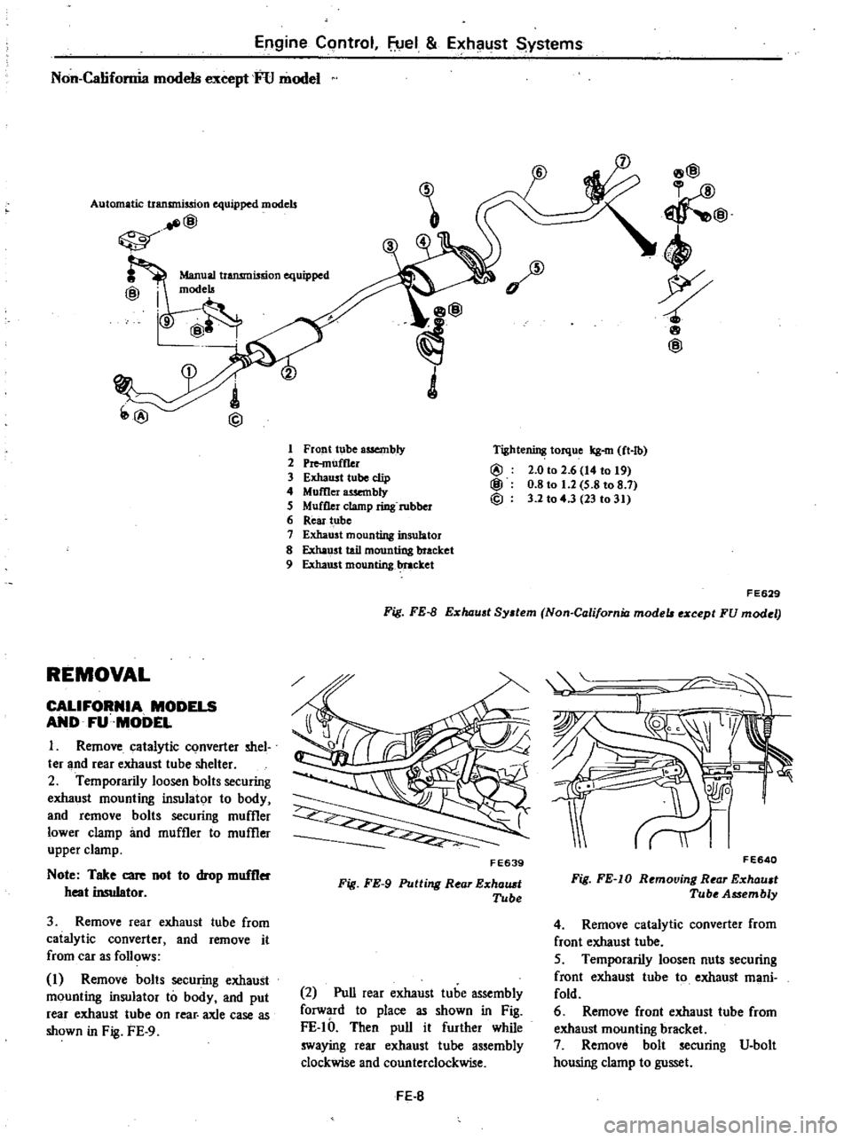
Front
tube
assembly
2
Pre
muff1er
3
Exhaust
tube
clip
4
Momer
wembly
5
Muffler
clamp
ring
rubber
6
Rear
tube
7
Exhaust
mounting
insulator
8
Exha
st
tail
mounting
bracket
9
Exhaust
mounting
1
ttacket
8@
@
4
wp
8
@
Tightening
torque
kg
m
ft
lb
@
2
0
to
2
6
14
to
t9
@
0
8
to
1
2
5
8
to
8
7
@
3
2
to
4
3
23
to
31
FE629
Fig
FE
B
E
haust
System
Non
California
mode
e
cept
FU
modet
FE639
Fig
FE
9
Putting
Rear
E
halUt
Tube
2
Pull
rear
exhaust
tube
assembly
forward
to
place
as
shown
in
Fig
FE
IO
Then
pull
it
further
while
swaying
rear
exhaust
tube
assembly
clockwise
and
counterclockwise
FE
B
II
F
E640
Fig
FE
IO
Removing
Rear
E
xhault
Tube
Assembly
4
Remove
catalytic
converter
from
front
exhaust
tube
5
Temporarily
loosen
nuts
securing
f
root
exhaust
tube
to
exhaust
mani
fold
6
Remove
front
exhaust
tube
from
exhaust
mounting
bracket
7
Remove
bolt
securing
V
bolt
housing
clamp
to
gusset
Page 412 of 548
DATSUN
210
Model
8310
Series
F
BODY
CONSTRUCTION
BODY
ALIGNMENT
BUMPER
DESCRIPTION
INSPECTION
FRONT
BUMPER
REAR
BUMPER
BODY
FRONT
END
RADIATOR
GRILLE
FRONT
APRON
COWL
TOP
GRILLE
FRONT
FENDER
FENDER
PROTECTOR
HOOD
HOOD
LOCK
CONTROL
DOORS
FRONT
DOOR
REAR
DOOR
4
door
Sedan
and
Wagon
BODY
REAR
END
TRUNK
LID
Sedan
SAC
K
000
R
Hatchabck
BODY
CONTENTS
BF
2
BF
4
BF
5
BF
5
BF
6
BF
8
SF
8
BF
9
BF
9
BF
9
BF
10
BF
10
BF
10
BF
11
BF
11
BF
12
BF
12
BF
15
BF
16
BF
16
BF
18
TAILGATE
Wagon
WINDSHIELD
AND
WINDOW
GLASS
WINDSHIELD
GLASS
REAR
WINDOW
GLASS
Sedan
and
Hatchback
REAR
WINDOW
GLASS
Wagon
SIDE
WINDOW
GLASS
2
Door
Sedan
and
Hatchback
REAR
QUARTER
WINDOW
GLASS
Hatchback
REAR
SIDE
WINDOW
GLASS
Wagon
INTERIOR
INSTRUMENT
PANEL
CONSOLE
BOX
SEAT
SEAT
BELT
TRIM
AND
MOLDING
ROOF
TRIMMING
BODY
SIDE
TRIM
AND
MOLDING
SPECIAL
SERVICE
TOOLS
BF
20
8F
21
SF
21
BF
22
SF
23
BF
26
BF
26
BF
27
SF
29
BF
29
SF
30
BF
30
BF
31
SF
32
BF
32
BF
32
BF
34
Page 420 of 548

RADIATOR
GRILLE
REMOVAL
AND
INSTALLATION
I
Open
hood
2
Remove
radiator
grille
attaching
screws
3
Detach
radiator
grille
from
front
end
of
car
4
Disconnect
front
combination
lamp
connectors
Then
remove
radia
tor
grille
S
Installation
is
in
the
reverse
order
of
removal
Note
a
Radiator
grille
is
made
of
plastic
so
do
not
use
excessive
force
b
Take
care
to
keep
any
oil
away
from
radiator
grille
FRONT
APRON
REMOVAL
AND
INSTALLATION
1
Remove
screws
attaching
front
apron
to
front
fender
2
Remove
screws
attaching
front
apron
to
hood
lock
stay
3
Remove
screws
attaching
front
apron
to
radiator
core
support
4
Remove
screws
attaching
front
apron
to
bracket
S
Installation
is
in
the
reverse
order
of
removal
Body
BODY
FRONT
END
8F7448
Fig
BF
11
Removing
RadiIJtor
Grille
S
1
i
oo
1
0
ole
I
Q
I
f
J
0
0
i
I
g
nl
o
A
BF
9
4
1
J
n
Jf
rf
BF745B
Fig
BF
12
Remouing
Front
Apron
Page 422 of 548

HOOD
ADJUSTMENT
Hood
can
be
adjusted
with
bolts
attaching
hood
to
hood
hinges
hood
lock
mechanism
and
hood
bumpers
Adjust
hood
for
an
even
fit
between
front
fenders
Adjust
hood
according
to
the
following
procedures
I
Adjust
hood
fore
and
aft
by
loosening
bolts
attaching
hood
to
hinge
and
repositioning
hood
2
Loosen
hood
bumper
lock
nuts
and
lower
bumpers
until
they
do
not
contact
front
of
hood
when
hood
is
closed
3
Set
striker
at
center
of
hood
lock
and
tighten
hood
lock
securing
bolts
temporarily
4
Raise
two
hood
bumpers
until
hood
is
flush
with
fenders
5
Tighten
hood
lock
securing
bolts
after
the
proper
adjustment
has
been
obtained
REMOVAL
AND
INSTALLATION
I
Open
hood
and
protect
body
with
covers
to
prevent
scratching
painted
surface
2
Mark
hood
hinge
locations
on
hood
for
proper
reinstallation
3
Holding
both
sides
of
hood
unscrew
bolts
securing
hinge
to
hood
and
remove
hood
This
operation
re
quires
two
men
4
Installation
is
in
the
reverse
order
of
removal
HOOD
LOCK
CONTROL
REMOVAL
AND
INSTALLATION
1
Disconnect
control
cable
from
hood
lock
2
Remove
hood
lock
3
Remove
control
cable
retaining
clamp
from
engine
compartment
4
Remove
hood
lock
release
handle
attaching
bolts
and
remove
hood
lock
release
handle
and
control
cable
from
dash
side
panel
5
Installation
is
in
the
reverse
order
of
removal
referring
to
Hood
Adjust
Body
@
C
ZiIfii
1
Striker
2
Hinge
3
Hood
bumper
4
Hood
lock
BF526B
Fig
BF
16
Adju
ting
Hood
1
Cable
bracket
2
Cable
clip
3
Hood
lock
4
Safety
catth
lever
5
Striker
3
II
5
1
LeS5
than
rJ
3
5
mm
O
l
BF746B
Fig
BF
17
Hood
Lock
Control
ment
6
Open
and
close
hood
several
times
to
check
operation
7
Make
sure
safety
catch
lever
re
tains
hood
properly
when
hood
lock
is
disengaged
Note
a
Lubricate
pivot
safety
catch
lever
and
return
spring
b
Inspect
safety
catch
lever
and
re
turn
spring
for
defonnation
fatigue
or
rusting
BF
ll