lock DATSUN 210 1979 Service Manual
[x] Cancel search | Manufacturer: DATSUN, Model Year: 1979, Model line: 210, Model: DATSUN 210 1979Pages: 548, PDF Size: 28.66 MB
Page 512 of 548

Air
Conditioning
6
Loosen
the
connection
at
the
center
fitting
of
manifold
gauge
for
a
Clockwise
few
seconds
to
purge
air
inside
charg
ing
hose
See
Fig
AC
14
Counterclockwise
j
3
@
I
Can
tap
handle
2
ChlcginS
hose
3
Needle
4
Refrigerant
can
AC246
Fig
AC
13
Can
Top
Purging
air
R
12
To
L9w
pressure
service
valve
AC247
Fig
AC
14
Purging
Air
Ta
High
pressure
service
valve
f
r
AC181A
Fig
AC
15
Discharging
System
AC
ll
DISCHARGING
SYSTEM
The
pressurized
refrigerant
gas
in
side
system
must
be
discharged
to
a
pressure
approaching
atmospheric
pressure
prior
to
evacuating
refrigerant
inside
system
This
operation
should
be
also
made
to
pennit
safe
removal
when
replacing
system
components
A
Close
high
and
low
pressure
valves
of
manifold
gauge
fully
2
Connect
two
charging
hoses
of
manifold
gauge
to
their
respective
service
valves
WARNING
Securely
connect
high
pressure
dis
charge
service
valve
to
that
of
manifold
gauge
with
a
hose
also
connect
low
pressure
suction
serv
ice
valve
to
that
of
manifold
gauge
For
locations
of
high
and
low
pres
sure
discharge
and
suction
service
valves
see
Fig
AC
29
3
Open
both
manifold
gauge
valves
slightly
and
slowly
discharge
refriger
ant
from
system
See
Fig
AC
15
WARNING
Protect
fingers
with
cloth
against
frostbite
by
refrigerant
when
con
necting
the
charging
hose
to
the
service
valve
or
disconnecting
it
therefrom
Nole
Do
not
allow
refrigerant
to
rush
out
Otherwise
compressor
oil
will
be
discharged
along
with
refriger
ant
EVACUATING
SYSTEM
I
Connect
high
and
low
pressure
charging
hoses
of
manifold
gauge
to
their
respective
service
valves
of
sys
tem
and
discharge
refrigerant
from
system
Refer
to
Discharging
System
WARNING
Securely
connect
high
pressure
dis
charge
service
valve
to
that
of
manifold
gauge
with
a
hose
also
connect
low
pressure
suction
servo
ice
valve
to
that
of
manifold
gauge
For
locations
of
high
and
low
pres
sure
discharge
and
wction
service
valves
see
Fig
AC
29
Page 519 of 548
for
Leaks
Here
is
how
leaks
are
stopped
I
Check
torque
on
the
connection
fitting
and
if
too
loose
tighten
to
the
proper
lorque
Check
for
gas
leakage
with
a
leak
detector
Air
Conditioning
2
If
leakage
continues
ven
after
the
fitting
has
been
retightened
dis
charge
refrigerant
from
system
disc
on
net
the
fittings
and
check
its
seating
face
for
damage
Always
replace
even
if
damage
is
slight
J
Check
compressor
6il
and
add
oil
if
required
4
Charge
refrigerant
and
recheck
for
gas
leaks
If
no
leaks
are
found
evacuate
and
charge
system
SERVICE
PROCEDURES
FAST
IDLE
ACTUATOR
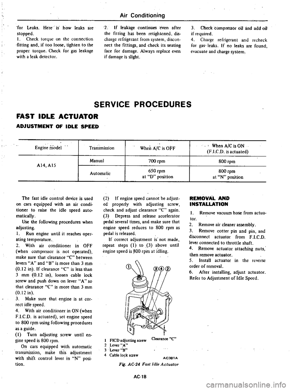
ADJUSTMENT
OF
IDLE
SPEED
Engine
model
Transmission
When
A
C
is
OFF
When
A
C
is
ON
F
LCD
is
actuated
Manual
700
rpm
800
rpm
A14
A15
Automatic
650
rpm
800
rpm
at
D
position
at
N
position
The
fast
idle
control
device
is
used
on
cars
equipped
with
an
air
condi
tioner
to
raise
the
idle
speed
auto
matically
Use
the
following
procedures
when
adjusting
1
Run
engine
until
it
reaches
oper
ating
temperature
2
With
air
conditioner
in
OFF
when
compressor
is
not
operated
make
sure
that
clearance
e
between
levers
A
and
8
is
more
than
J
mm
0
12
in
If
clearance
C
is
less
than
J
mm
0
12
in
loosen
cable
lock
screw
and
push
down
on
lever
A
so
that
clearance
C
is
more
than
J
mm
0
12
in
3
Make
sure
that
engine
is
at
cor
rect
idle
speed
4
With
air
conditioner
in
ON
when
F
LC
D
is
actuated
set
engine
speed
to
800
rpm
using
following
procedures
as
a
guide
I
Turn
adjusting
screw
until
en
gine
speed
is
800
rpm
On
cars
equipped
with
automatic
transmission
make
this
adjustment
with
shift
control
lever
in
N
posi
tion
2
If
engine
speed
cannot
be
adjust
ed
properly
with
adjusting
screw
check
and
adjust
clearance
e
again
3
Depress
and
release
accelerator
pedal
several
times
and
make
sure
that
engine
speed
reduces
to
800
rpm
as
pedal
is
released
If
correct
adjustment
is
not
made
repeat
steps
I
to
3
above
until
engine
speed
is
800
rpm
at
idling
1
FlCD
adjusting
screw
2
Lever
A
3
Lever
B
4
Cable
lo
k
screw
Clearance
e
AC381
A
Fig
AC
24
Fast
Idle
Actuotor
AC
18
REMOVAL
AND
INSTALLATION
Remove
vacuum
hose
from
actua
tor
2
Remove
air
cleaner
assembly
3
Remove
cotter
pin
and
pin
and
disconnect
actuator
from
F
LC
D
lever
connected
to
throttle
shaft
4
Remove
actuator
attaching
nuts
then
remove
actuator
5
Install
actuator
in
the
reverse
order
of
removal
6
After
installing
adjust
actuator
Refer
to
Adjustment
of
Idle
Speed
Page 520 of 548

Air
Conditioning
IDLER
PULLEY
AND
COMPRESSOR
DRIVE
BELT
ADJ
USTMENT
OF
BELT
TENSION
Idler
pulley
Alternator
Crankshaft
pulley
Unit
mm
in
Idler
pulley
Fig
AC
25
Belt
Tension
Specified
compressor
belt
tension
is
8
to
12
mm
0
31
to
0
47
in
when
thumb
pressure
of
10
kg
22
Ib
is
applied
midway
between
idler
pulley
and
compressor
pulley
1
Loosen
idler
pulley
lock
nut
and
then
adjust
pulley
by
turning
adjusting
bolt
2
After
adjustment
tighten
idler
pulley
lock
nut
bolt
3
Remove
idler
pulley
4
Install
pulley
in
the
reverse
order
of
removal
5
Adjust
compressor
belt
tension
REMOVAL
AND
INSTALLATION
1
Jack
up
front
of
car
and
remove
under
cover
2
Remove
idler
pulley
lock
nut
and
loosen
belt
tension
adjusting
Fig
AC26
AC382A
Idler
Pulley
TIghtening
torque
@
3
7
to
5
1
kg
m
27
to
37
ft
lb
AC383A
Fig
AC
27
Compressor
and
Bracket
AC
19
REMOVAL
I
Operate
compressor
if
possible
at
engine
idling
speed
with
air
condi
tioner
controls
set
for
maximum
cool
ing
and
high
blower
speed
for20
to
30
minutes
with
all
windows
open
to
return
oil
into
compressor
2
Disconnect
battery
ground
cables
and
compressor
lead
wire
at
con
nector
3
Discharge
refrigerant
from
cool
ing
system
Refer
to
Discharging
Sys
tem
4
Jack
up
front
of
car
and
remove
under
cover
5
Loosen
idler
pulley
lock
nut
and
loosen
tension
adjusting
bolt
fully
Remove
compressor
drive
belt
See
Fig
AC
26
6
Remove
high
and
low
flexible
hoses
from
compressor
WARNING
Gradually
loosen
discharge
side
hose
fitting
and
remove
it
after
remaining
pressure
has
been
re
leased
CAUTION
Be
sure
to
immediately
put
plug
in
flexible
hose
and
compressor
open
ings
7
Remove
bolts
securing
lower
part
of
compressor
8
Remove
bolts
securing
upper
part
of
compressor
Hold
compressor
with
one
hand
when
removing
bolts
and
then
remove
compressor
With
compressor
clutch
up
lift
compressor
out
with
both
hands
CAUTION
00
not
attempt
to
leave
the
com
pressor
on
its
side
or
upside
down
for
more
than
10
minutes
as
the
compressor
oil
will
enter
the
low
pressure
chambers
If
under
that
condition
compressor
should
be
oper
ated
suddenly
internal
damage
would
result
To
expel
oil
from
chambers
hand
crank
compressor
several
times
in
its
installed
condition
Page 523 of 548
to
DISASSEMBLY
AND
ASSEMBLY
y
1
7
1
r
II
l
1
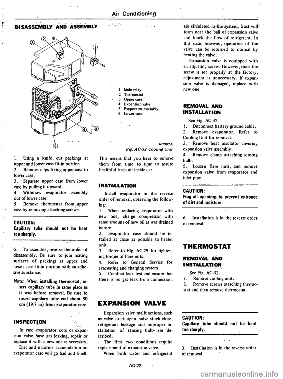
Using
a
knife
cut
packings
at
upper
and
lower
case
fit
in
portion
2
Remove
clips
fixing
upper
case
to
lower
case
3
Separate
upper
case
from
lower
case
by
pulling
it
upward
4
Withdraw
evaporator
assembly
out
oflower
case
5
Remove
thermostat
from
upper
case
by
removing
attaching
screWs
CAUTION
Capillary
tube
should
not
be
bent
too
sharply
6
To
assemble
reverse
the
order
of
disassembly
Be
sure
to
join
mating
surfaces
of
packings
at
upper
and
lower
case
fit
in
portion
with
an
adhe
sive
substance
Note
When
installing
thermostat
in
sert
capillary
tube
in
same
place
as
it
was
before
removal
Be
sure
to
insert
capillary
tube
end
about
50
em
19
7
in
from
evaporator
core
INSPECT
ON
In
case
evaporator
core
or
expan
sion
valve
have
gas
leaking
repair
or
replace
it
with
a
new
one
as
necessary
Dirt
and
nicotine
accumulation
on
evaporator
case
will
go
b
d
and
smell
Air
Conditioning
1
Mainrelay
2
Thermostat
3
Upper
case
4
Expansion
valve
5
Evaporator
assembly
6
Lower
case
ID
AC387A
Fig
AC
32
Cooling
Unit
This
means
that
you
have
to
remove
them
from
time
to
time
to
assure
healthful
fresh
air
inside
car
INSTAllATION
Install
evaporator
in
the
reverse
order
of
removal
observing
the
follow
ing
I
When
replacing
evaporator
with
new
one
charge
compressor
with
same
amount
of
new
oil
as
was
drained
before
2
Evaporator
case
should
be
in
stalled
as
close
s
possible
to
heater
unit
3
Refer
to
Fig
AC
29
for
tighten
ing
torque
of
flare
nuts
4
Refer
to
General
Service
for
evacuating
and
charging
system
5
Conduct
leak
test
and
ensu
e
that
there
is
no
gas
leak
from
conne
tion
EXPANSION
VALVE
Expansion
valve
malfunctions
such
as
valve
stuck
open
valve
stuck
close
refrigerant
leakage
and
improper
in
stall
tion
of
sensing
bulb
are
de
scribed
The
first
two
conditions
require
replacement
of
expansion
valve
When
both
water
and
refrigerant
AC
22
are
circulated
in
the
system
frost
cwill
form
near
the
ball
of
expansion
alve
and
block
the
flow
of
refrigerant
In
this
case
however
operation
of
the
valve
can
be
returned
to
normal
by
heating
the
valve
Expansion
valve
is
equipped
with
an
adjusting
screw
However
since
the
screw
is
set
properly
at
the
factory
adjustment
is
unnecessary
If
expan
sion
valve
is
damaged
replace
with
new
one
RIEMOV
L
AND
INSTALlATION
See
Fig
AC
32
Disconnect
baltery
ground
cable
2
Remove
ev
porator
Refer
to
Cooling
Unit
for
removal
3
Remove
heat
insulator
covering
expansion
valve
assembly
4
Remove
clamp
attaching
sensing
bulb
5
Loosen
flare
nuts
and
remove
expansion
valve
from
evaporator
and
inlet
pipe
CAUTION
Plug
all
openings
to
prevent
entrance
of
dirt
and
moisture
6
Installation
is
ill
the
reverse
order
of
removal
THERMOSTAT
REMOVAL
AND
INSTALlATION
See
Fig
AC
32
Remove
cooling
unit
2
Remove
screws
attaching
thenno
stat
and
then
remove
thermostat
CAUTION
Capillary
tube
should
not
be
bent
too
sharply
3
Installation
is
in
the
reverse
order
of
removal
Page 526 of 548
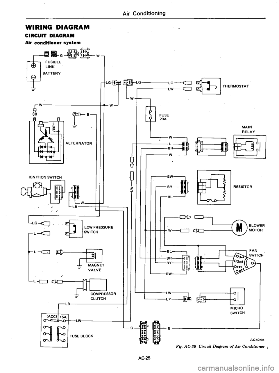
WIRING
DIAGRAM
CIRCUIT
DIAGRAM
Air
conditioner
system
G
DD
w
FUSIBLE
LINK
I
BATTERY
LG
Lr
LG
c
J
LW
J
I
THERMOSTAT
W
W
r
B
B
8
ALTERNATOR
IGNITION
SWITCH
il
W
LB
LLG
J
LOW
PRESSURE
SWITCH
L
c
J
L
c
J
l
J
MAGNET
VALVE
L
c
J
CJ
C
COMPRE
SOR
CLUTCH
LIT
IACC
15A
L1
3
E
FUSE
BLOCK
Air
Conditioning
W
1
8
t
FUSE
20A
MAIN
RELAY
J
rn
W
I
fJ
RESISTOR
Dt
J
M
BLOWER
MOTOR
W
c
J
c
J
C
r
BvM
LW
LY
I
MICRO
SWITCH
B
AC404A
Fig
AC
39
Circuit
Diagram
of
Air
Conditioner
I
AC
25
Page 540 of 548

Condition
I
FAULTY
CONDENSER
I
I
@
@
AC215A
I
HIGH
PRESSURE
liNE
BLOCKED
I
r
@
@
AC216A
I
FAULTY
COMPRESSOR
I
r
j
@
rg
AC217A
Air
Conditioning
o
cooling
action
engine
may
overheat
Bubbles
appear
in
sight
glass
of
drier
Suction
line
is
very
hot
Insufficient
cooling
Frosted
high
pressure
liquid
line
Insufficient
cooling
AC
39
Probable
cause
Condenser
is
often
found
not
functioning
well
Drier
clogged
or
restric
tion
in
high
pressure
line
Internal
problem
in
com
pressor
or
damaged
gasket
and
valve
Corrective
action
Check
fan
belt
and
fluid
coupling
Check
condenser
for
dirt
accumulation
Check
engine
coqling
system
for
overheat
Check
for
refrigerant
overcharge
Note
If
pressure
remains
high
in
spite
of
aU
above
actions
taken
re
move
and
inspect
the
condenser
for
possible
oil
clogging
I
Discharge
system
2
Remove
receiver
drier
or
strainer
and
replace
it
3
Evacuate
and
charge
system
I
Discharge
system
2
Remove
and
check
compressor
3
Repair
or
replace
com
pressor
4
Check
oil
level
5
Replace
receiver
drier
6
Evacuate
and
charge
system
Page 543 of 548
r
Air
Conditioning
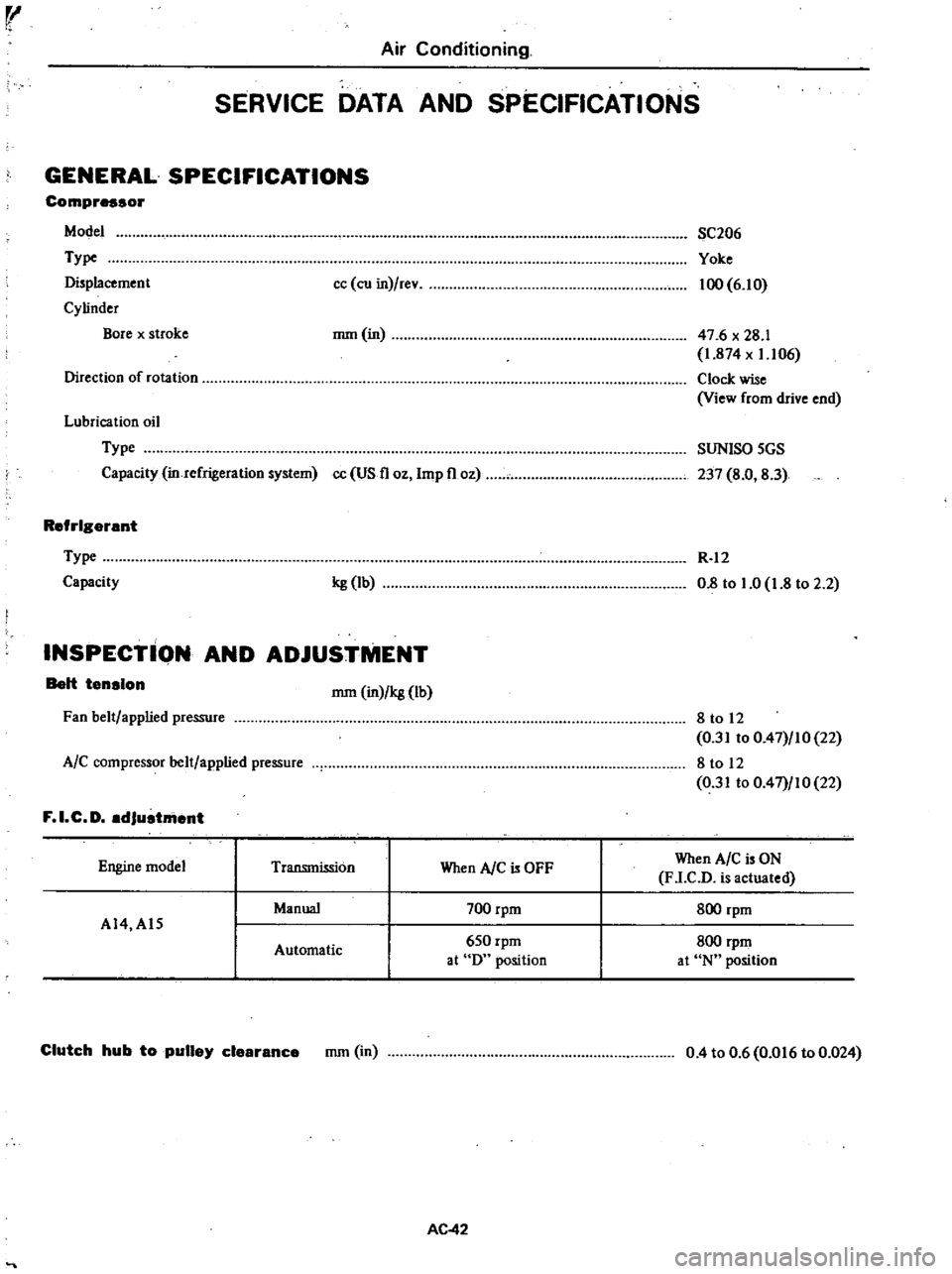
SERVICE
DATA
AND
SPECIFICATIONS
GENERAL
SPECIFICATIONS
Compressor
Model
Type
Displacement
Cylinder
Bore
x
stroke
cc
ell
in
rev
SC206
Yoke
100
6
10
mm
in
47
6
x
28
1
1
874
x
1
106
Clock
wise
View
from
drive
end
Direction
of
rotation
Lubrication
oil
Type
Capacity
in
refrigeration
system
cc
US
11
OZ
Imp
11
oz
SUNISO
5GS
237
8
0
8
3
Refrigerant
Type
Capacity
kg
lb
R
12
0
8
to
1
0
1
8
to
2
2
INSPECTION
AND
ADJUSTMENT
Belt
tension
mm
in
kg
lb
Fan
belt
applied
pressure
8
to
12
0
31
to
0
47
10
22
8
to
12
0
31
to
0
47
10
22
A
C
compressor
belt
applied
pressure
F
I
C
D
adJustment
Automatic
700
rpm
650
rpm
at
Du
position
When
AlC
is
ON
F
LC
D
is
actuated
800
rpm
800
rpm
at
Nu
position
Engine
model
Transmission
When
AlC
OFF
Manual
AI4
AI5
Clutch
hub
to
pulley
clearance
mm
in
0
4
to
0
6
0
016
to
0
024
AC
42
Page 544 of 548
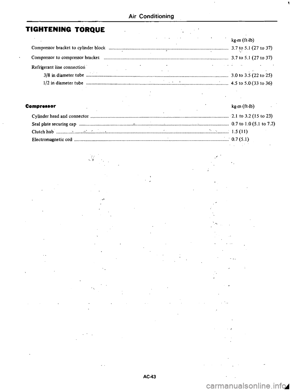
Air
Conditioning
TIGHTENING
TORQUE
Compressor
bracket
to
cylinder
block
kg
m
ft
lb
3
7
to
5
1
27
to
37
37
to
5
1
27
to
37
Compressor
to
compressor
bracket
Refrigerant
line
connection
3
8
in
diameter
tube
1
2
in
diameter
tube
3
0
to
3
5
22
to
25
4
5
to
5
0
33
to
36
Compre
or
Electromagnetic
coil
kg
m
ft
lb
2
1
to
3
2
15
to
23
0
7
to
1
0
5
1
to
7
2
1
5
11
0
7
5
1
Cylinder
head
and
connector
Seal
plate
securing
cap
Clutch
hub
AC
43
olIIl