manual transmission DATSUN 210 1979 User Guide
[x] Cancel search | Manufacturer: DATSUN, Model Year: 1979, Model line: 210, Model: DATSUN 210 1979Pages: 548, PDF Size: 28.66 MB
Page 84 of 548

u
V
O
I
MAX
Ii
1i
i
iT
1
I
I
11
1
i
MINij
o
f
G
p
rl
MAX
ii
i
p
It
ot
MINi
II
L
Cooling
System
l
CQ074
Pressure
relief
valve
opens
f
C007S
Vacuum
valve
opens
INSPECTION
1
Check
the
amount
of
coolant
in
the
reservoir
tank
If
the
coolant
level
is
below
the
MIN
level
remove
the
re
servoirtank
ruler
cap
and
add
enough
oolant
to
reach
MAX
level
If
the
reservoir
tank
is
empty
check
the
coolantlevel
in
the
radiator
If
the
coolant
in
the
radiator
is
insuf
ficient
pour
it
into
radiator
up
to
the
radiator
cap
and
also
pour
it
into
the
reservoir
tank
until
MAX
level
If
the
coolant
in
the
reservoir
tank
d
ecreases
abnormally
rapid
check
for
a
leak
in
the
cooling
system
REMOVAL
AND
INSTALLATION
1
Reservoir
tank
is
only
inserted
to
reservoir
tank
bracket
and
can
be
easily
removed
To
install
reservoir
tank
reverse
the
order
of
remova
Fig
CO
12
Opefation
of
ReserVoir
Tank
SERVICE
DATA
AND
SPECIFICATIONS
Thermostat
Valve
opening
temperature
Oc
OF
Maximum
valve
lift
mmjOC
in
oF
Radiator
Type
Manual
transmission
Automatic
tralUJ1lission
Cap
relief
pressure
kg
cm2
psi
Testing
pressure
kg
cm
2
psi
Fan
Fan
belt
deflection
mm
in
cO
6
Temperate
type
Frigid
type
Tropical
type
82
180
88
190
76
5
I
70
8
95
8
loo
8
90
0
3
I
203
0
31j2
i
2
0
31
194
Corrugated
fm
type
Corrugated
fm
type
equipped
with
oil
cooler
0
9
I
3
1
6
23
8
to
12
0
31
to
0
47
Page 95 of 548
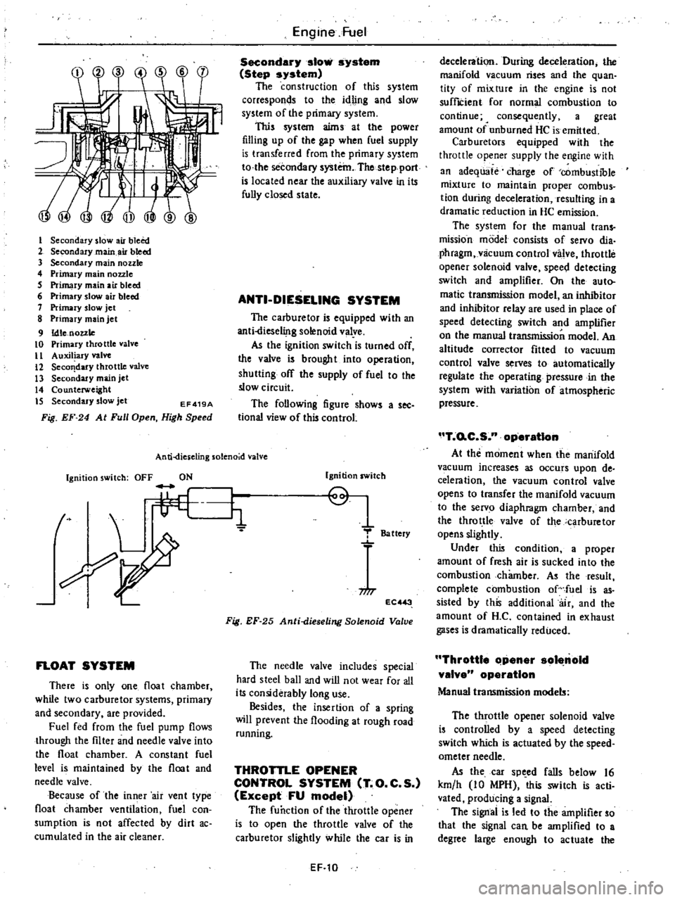
I
Secondary
slow
air
bleed
2
Secondary
main
air
bleed
3
Secondary
main
nozzle
4
Primary
main
nozzle
5
Primary
main
air
bleed
6
Primary
slow
air
bleed
7
Primary
slow
jet
8
Primary
main
jet
9
Idle
nozzle
10
Primary
throttle
valve
II
Auxiliary
valve
12
Seco
dary
throttle
valve
13
Secondary
main
jet
14
Counterweight
IS
Secondary
slow
jet
EF419A
Fig
EF
24
At
Full
Open
High
Speed
Engine
Fuel
Secondary
slow
system
Step
system
The
construction
of
this
system
corresponds
to
the
idling
and
slow
system
of
the
primary
system
This
system
aims
at
the
power
filling
up
of
the
gap
when
fuel
supply
is
transferred
from
the
primary
system
to
the
secondary
system
The
stepport
is
located
near
the
auxiliary
valve
in
its
fully
closed
state
ANTI
DIESELING
SYSTEM
The
carburetor
is
equipped
with
an
anti
liese1i
lg
solenoid
valye
As
the
ignition
switch
is
turned
off
the
valve
is
brought
into
operation
shutting
off
the
supply
of
fuel
to
the
slow
circuit
The
following
figure
shows
a
see
tional
view
of
this
control
An
ti
dies
eling
solenoid
valve
Ignition
switch
OFF
ON
t
L
li
FLOAT
SYSTEM
There
is
only
one
float
chamber
while
two
carburetor
systems
primary
and
secondary
are
provided
Fuel
fed
from
the
fuel
pump
flows
through
the
filter
and
needle
valve
into
the
float
chamber
A
constant
fuel
level
is
maintained
by
the
float
and
needle
valve
Because
of
the
inner
air
vent
type
float
chamber
ventilation
fuel
con
sumption
is
not
affected
by
dirt
ac
cumulated
in
the
air
cleaner
Ignition
switch
Q
1
T
Battery
niT
EC
3
Fig
EF
25
Anti
dieseling
Solenoid
Valve
The
needle
valve
includes
special
hard
steel
ball
and
wiD
not
wear
for
all
its
considerably
long
use
Besides
the
insertion
of
a
spring
will
prevent
the
flooding
at
rough
road
running
THROTTLE
OPENER
CONTROL
SYSTEM
T
O
C
S
Except
FU
model
The
function
of
the
throttle
opener
is
to
open
the
throttle
valve
of
the
carburetor
slightly
while
the
car
is
in
EF
10
deceleration
During
deceleration
the
manifold
vacuum
rises
and
the
quan
tity
of
mixture
in
the
engine
is
not
suffICient
for
normal
combustion
to
continue
4
consequently
a
great
amount
of
unburned
HC
is
emitted
Carburetors
equipped
with
the
throttle
opener
supply
the
engine
with
an
adequate
charge
of
combustible
mixture
to
maintain
proper
combus
tion
during
deceleration
resulting
in
a
dramatic
reduction
in
HC
emission
The
system
for
the
manual
trans
mission
model
consists
of
servo
dia
phragm
vlicuum
control
valve
throttle
opener
solenoid
valve
spee
l
detecting
switch
and
amplifier
On
the
auto
matic
transmission
model
an
inhibitor
and
inhibitor
relay
are
used
in
place
of
speed
detecting
switch
and
amplifier
on
the
manual
transmission
model
An
altitude
corrector
fitted
to
vacuum
control
valve
serves
to
automatically
regulate
the
operating
pressure
in
the
system
with
variation
of
atmospheric
pressure
T
o
C
S
n
operatIon
At
the
moment
when
the
manifold
vacuum
increases
as
occurs
upon
de
celeration
the
vacuum
control
valve
opens
to
transfer
the
manifold
vacuum
to
the
servo
diaphragm
chamber
and
the
throttle
valve
of
the
carburetor
opens
slightly
Under
this
condition
a
proper
amount
of
fresh
air
is
sucked
into
the
combustion
chamber
As
the
result
complete
combustion
of
fuel
is
as
sisted
by
this
additional
air
and
the
amount
of
H
C
contained
in
exhaust
gases
is
dramatically
reduced
Throttle
Clpener
sol
nold
valve
operation
Manual
transmission
models
The
throttle
opener
solenoid
valve
is
controlled
by
a
speed
detecting
switch
which
is
actuated
by
the
speed
ometer
needle
As
the
car
sp
ed
falls
below
16
km
h
10
MPH
this
switch
is
acti
vated
producing
a
signal
The
signal
is
led
to
the
amplifier
so
that
the
signal
can
be
amplified
to
a
degree
large
enough
to
actuate
the
Page 96 of 548
throttle
opener
solenoid
valve
The
throttle
opener
solenoid
valve
is
actuated
and
the
servo
diaphragm
chamber
is
opened
to
the
atmosphere
In
this
case
the
seIVo
diaphragm
does
not
opera
te
Engine
Fuel
Automatic
transmission
models
As
long
as
the
shift
lever
is
in
the
N
or
p
position
the
inhibitor
switch
on
the
transmission
is
turned
on
and
the
throttle
opener
solenoid
valve
is
actuated
Under
this
condition
the
seIVo
diaphragm
does
not
operate
because
of
the
same
reason
as
men
tioned
for
the
manual
transmission
model
ON
Car
peed
betow
t6
km
h
to
mph
OFF
Car
peed
above
16
km
h
to
mph
To
intake
manifold
j
lJl
11
1
ti
i
ljn
L
o
1
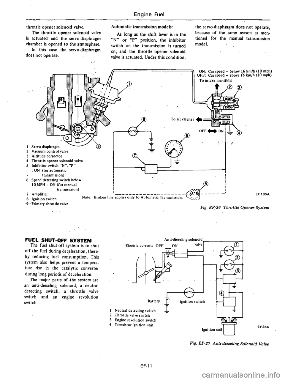
Servo
diaphragm
2
Vacuum
control
valve
3
Altitude
corrector
4
Throttle
opener
solenoid
valve
5
Inhibitor
switch
N
p
ON
for
automatic
transmission
6
Speed
detecting
switch
below
10
MPH
ON
for
manual
transmission
7
Amplifier
8
Ignition
switch
9
Primary
throttle
valve
Note
FUEL
SHUT
OFF
SYSTEM
The
fuel
shut
off
system
is
to
shut
off
the
fuel
during
deceleration
there
by
reducing
fuel
consumption
This
system
also
helps
prevent
a
tempera
ture
rise
in
the
catalytic
converter
during
long
periods
of
deceleration
The
major
parts
of
the
system
are
an
anti
dieseling
solenoid
a
neutral
detecting
switch
a
throttle
valve
switch
and
an
engine
revolution
switch
e
1
l
6
I
I
I
I
I
I
I
I
I
l
L
I
Broken
tine
applies
only
to
Automatic
Transmission
7
Anti
dieseling
solenoid
Electric
current
OFF
ON
valve
I
I
h
L
Battery
I
Neutral
detecting
switch
l
2
Throttle
valve
switch
3
Engine
revolution
switch
4
Transistor
ignition
unit
o
Ignition
switch
EF105A
Fig
EF
26
Throttle
Opener
System
ill
Ignition
coil
U
EF846
Fig
EF
27
Anti
dieseling
Solenoid
Valve
EF
11
Page 100 of 548
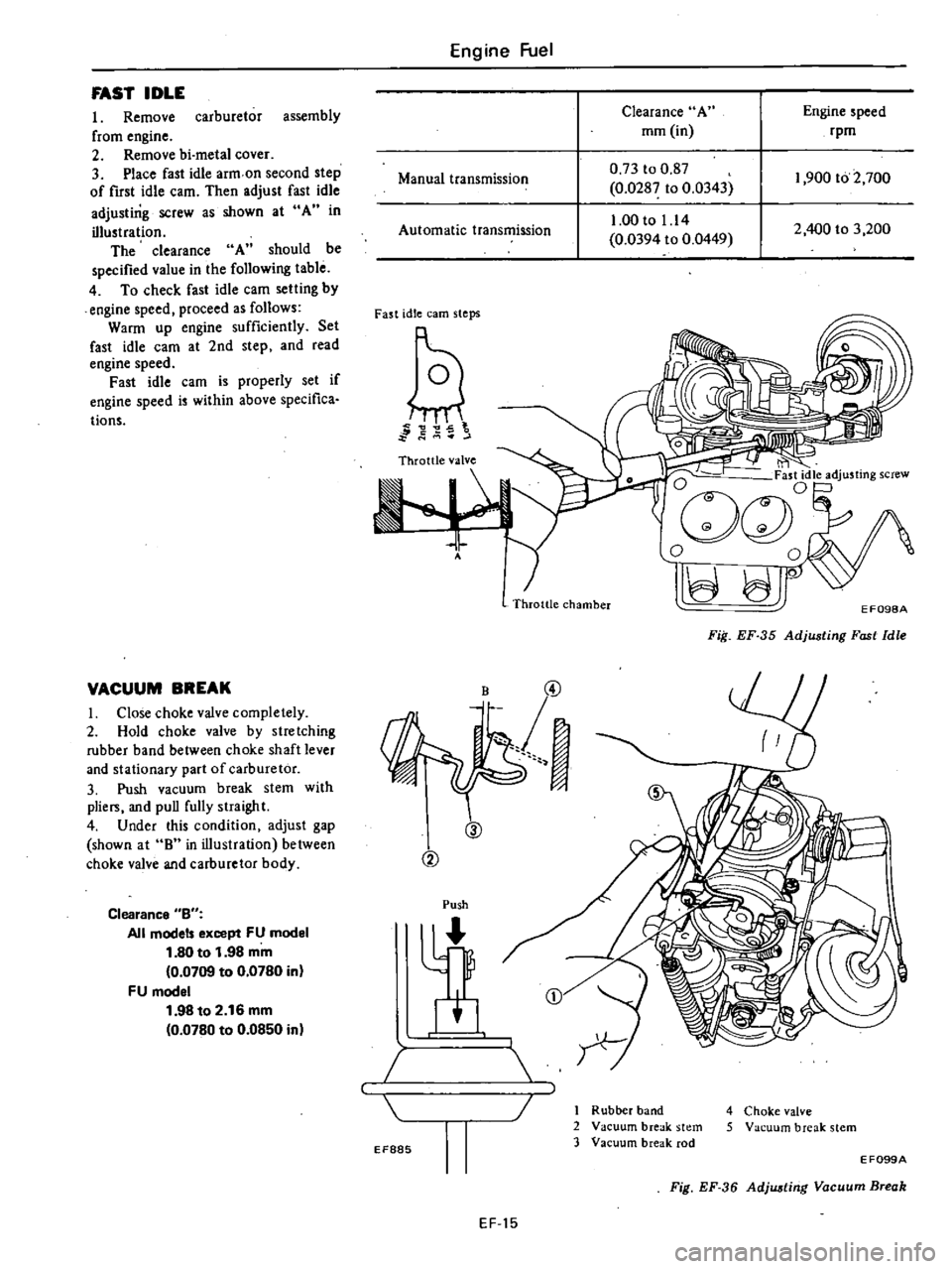
FAST
IDLE
I
Remove
carburetor
assembly
from
engine
2
Remove
bi
metal
cover
3
Place
fast
idle
arm
on
second
step
of
first
idle
cam
Then
adjust
fast
idle
adjusting
screw
as
shown
at
A
in
illustration
The
clearance
A
should
be
specified
value
in
the
following
table
4
To
check
fast
idle
cam
setting
by
engine
speed
proceed
as
follows
Warm
up
engine
sufficiently
Set
fast
idle
cam
at
2nd
step
and
read
engine
speed
Fast
idle
cam
is
properly
set
if
engine
speed
is
within
above
specifica
Hons
VACUUM
BREAK
I
Close
choke
valve
completely
2
Hold
choke
valve
by
stretching
rubber
band
between
choke
shaft
lever
and
stationary
part
of
carburetor
3
Push
vacuum
break
stem
with
plie
and
puD
fully
straight
4
Under
this
condition
adjust
gap
shown
at
8
in
illustration
between
choke
valve
and
carburetor
body
Clearance
Bu
All
model
except
FU
model
1
80
to
1
98
mm
0
0709
to
0
0780
in
FU
model
1
98
to
2
16
mm
0
0780
to
0
0850
in
Engine
Fuel
Clearance
A
mm
in
Engine
speed
rpm
Manual
transmission
0
73
to
0
87
0
0287
to
0
0343
1
00
to
1
14
0
0394
to
0
0449
2
400
to
3
200
1
900
to
2
700
Automatic
transmission
Fast
idle
earn
steps
g
g
2
5
t
to
J
A
ti
Ogc
j
jdle
adjusting
screw
o
0
II
r
Throttle
chamber
EF098A
Fiil
EF
35
Adjusting
Fast
Idle
@
B
@
cv
Push
I
4
Choke
valve
5
Vacuum
break
stem
EF885
1
Rubber
band
2
Vacuum
break
stem
3
Vacuum
break
rod
E
F099A
Fig
EF
36
Adjwtirig
Vacuum
Break
EF
15
Page 103 of 548
Engine
Fuel
Upon
completion
of
adjustment
make
sure
that
link
system
opera
tes
smoothly
It
is
necessary
to
remove
Carburetor
from
engine
in
adjusting
this
accelera
tor
pump
stroke
limiter
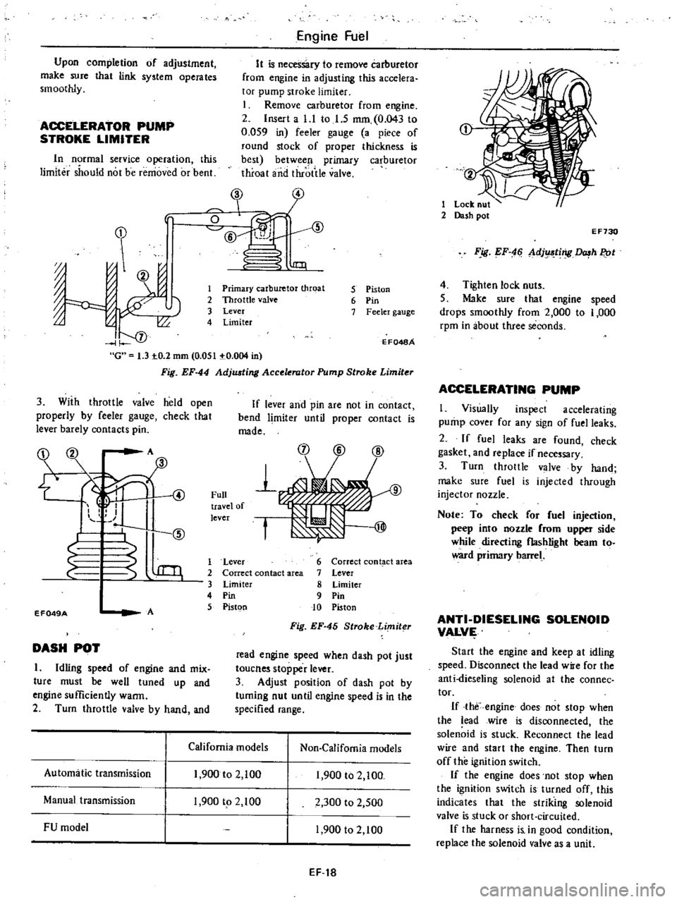
1
Remove
carburetor
from
engine
2
Insert
a
l
l
to
I
S
mm
0
043
to
0
059
in
feeler
gauge
a
piece
of
round
stock
of
proper
thickness
is
best
betwee
l
primary
ca
buretor
throat
and
throtile
valve
ACCELERATOR
PUMP
STROKE
LIMITER
In
rmal
service
operation
this
limiter
should
not
be
removed
or
bent
In
J
0
ID
@
l
1IJl
J
J
00
I
f
oj
G
1
3
IO
2
mm
0
051
IO
004
in
Fig
EF
44
AdjlUting
Acce
rator
Pump
Stroke
Limiter
1
Primary
carburetor
throat
2
Throttle
valve
3
Lever
4
Limiter
5
Piston
6
Pin
7
Feeler
gauge
E
F048A
3
With
throttle
valve
held
open
properly
by
feeler
gauge
check
that
lever
barely
contacts
pin
If
lever
and
pin
are
not
in
contact
bend
limiter
until
proper
contact
is
made
OZ
00
A
fID
1
S
@
4
1
Full
travel
of
lever
f
EF049A
A
1
Lever
2
Correct
contact
area
3
Limiter
4
Pin
5
Pistgn
6
Correct
cont
ct
area
7
Lever
8
Limiter
9
Pin
10
Piston
Fig
EF
45
Stroke
Limiter
DASH
POT
I
Idling
speed
of
engine
and
mix
ture
must
be
well
tuned
up
and
engine
sufficiently
warm
2
Turn
throttle
valve
by
hand
and
read
engine
speed
when
dash
pot
just
toucnes
stopper
lever
3
Adjust
position
of
dash
pot
by
tuming
nut
until
engine
speed
is
in
the
specified
range
California
models
Non
Califomia
models
Automatic
transmission
1
900
to
2
100
1
900
to
2
100
Manual
transmission
1
900
tp
2
100
2
300
to
2
500
FU
model
1
900
to
2
100
EF
t8
1
Lock
nut
2
Dash
pot
E
F730
F
ig
EF
4
Ll
dj
ting
h
P
ot
4
Tighten
lock
nuts
5
Make
sure
that
engine
speed
drops
smoothly
from
2
000
to
1
000
rpm
in
about
three
seconds
ACCELERATING
PUMP
I
Visually
inspect
accelerating
pump
cover
for
any
sign
of
fuel
leaks
2
If
fuel
leaks
are
found
check
gasket
and
replace
if
necessary
3
Turn
throttle
valve
by
hand
make
sure
fuel
is
injected
through
injector
nozzle
Note
To
check
or
fuel
injection
peep
into
nozzle
rom
upper
side
while
directing
flashlight
beam
to
ward
primary
barrel
ANTI
DIESELING
SOLENOID
VALVI
Start
the
engine
and
keep
at
idling
speed
Disconnect
the
lead
w
e
for
the
anti
dieseling
solenoid
at
the
connec
tor
If
the
engine
does
not
stop
when
the
lead
wire
is
disconnected
the
solenoid
is
stuck
Reconnect
the
lead
wire
and
start
the
engine
Then
turn
off
the
ignition
switch
If
the
engine
does
not
stop
when
the
ignition
switch
is
turned
off
this
indicates
that
the
striking
solenoid
valve
is
stuck
or
short
circuited
If
the
harness
i
in
good
condition
replace
the
solenoid
valve
as
a
unit
Page 104 of 548
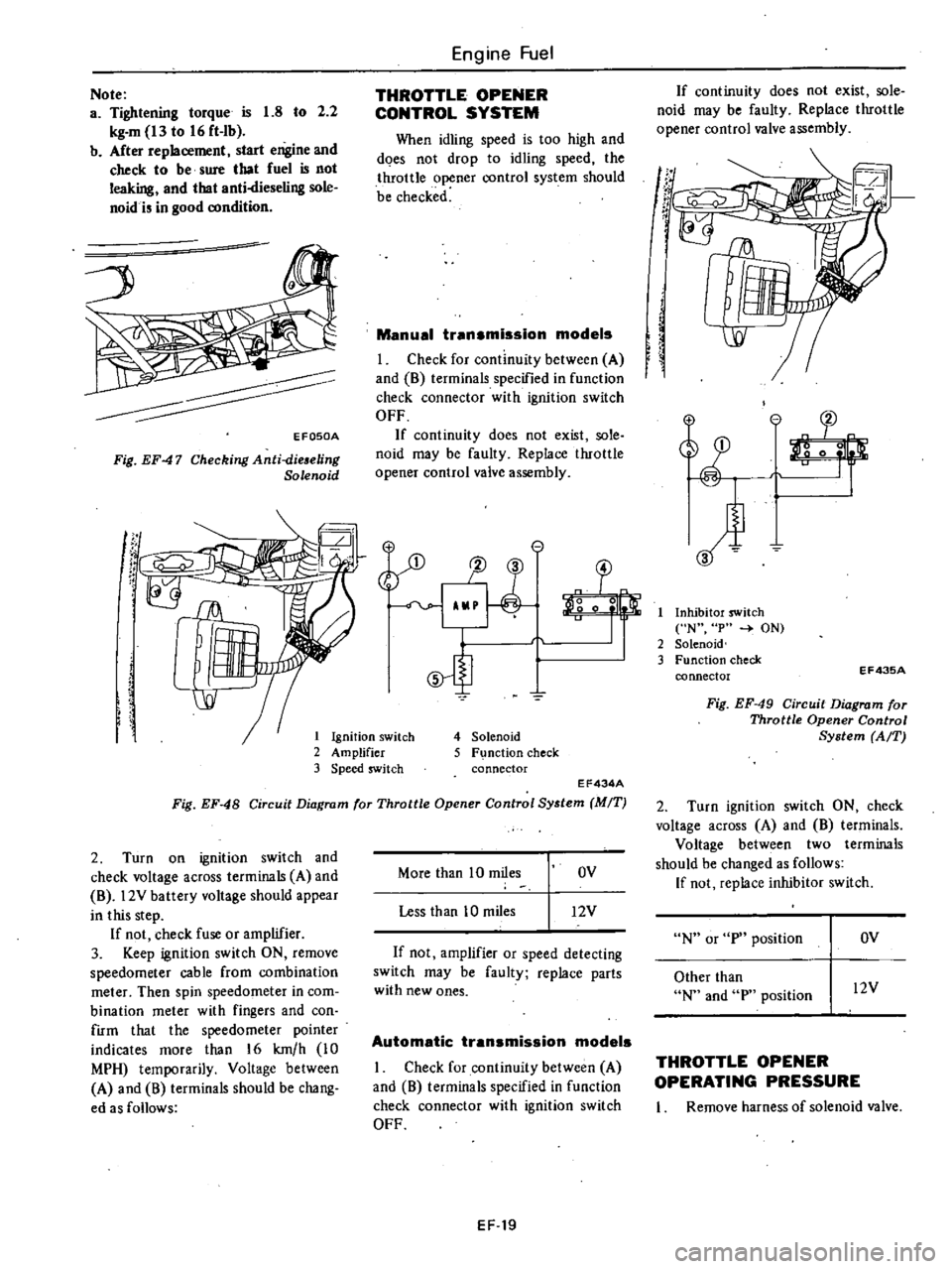
1
Ignition
switch
2
Amplifier
3
Speed
switch
Note
a
Tightening
torque
is
1
8
to
2
2
kg
m
13
to
16
ft
Ib
b
After
replacement
start
engine
and
check
to
be
sure
that
fuel
is
not
leaking
and
that
anti
dieseling
sole
noid
i
in
good
condition
EFOSOA
Fig
EF47
Checking
Anti
dieaeling
Solenoid
l
SJ
Engine
Fuel
THROTTLE
OPENER
CONTROL
SYSTEM
When
idling
speed
is
too
high
and
does
not
drop
to
idling
speed
the
throttle
opener
control
system
should
be
checked
Manual
transmission
models
I
Check
for
continuity
between
A
and
8
terminals
specified
in
function
check
connector
with
ignition
switch
OFF
If
continuity
does
not
exist
sole
noid
may
be
faulty
Replace
throttle
opener
control
valve
assembly
e
1J
3
o
0
5
4
Solenoid
5
F
nction
check
connector
EF434A
Fig
EF
48
Circuit
Diagram
for
Throttle
Opener
Control
System
MIT
2
Turn
on
ignition
switch
and
check
voltage
across
terminals
A
and
8
l2V
battery
voltage
should
appear
in
this
step
If
not
check
fuse
or
amplifier
3
Keep
ignition
switch
ON
remove
speedometer
cable
from
combination
meter
Then
spin
speedometer
in
com
bination
meter
with
fingers
and
con
firm
that
the
speedometer
pointer
indicates
more
than
16
km
h
10
MPH
temporarily
Voltage
between
A
and
8
terminals
should
be
chang
ed
as
follows
More
than
10
miles
OV
Less
than
10
miles
12V
If
not
amplifier
or
speed
detecting
switch
may
be
faulty
replace
parts
with
new
ones
Automatic
transmission
models
I
Check
for
continuity
between
A
and
8
terminals
specified
in
function
check
connector
with
ignition
switch
OFF
EF
19
If
continuity
does
not
exist
sole
noid
may
be
faulty
Replace
throttle
opener
control
valve
assembly
If
t
r
If
I
Inhibitor
switch
N
p
ON
2
Solenoid
3
Function
check
connector
EF43SA
Fig
EF
49
Circuit
Diagram
for
Throttle
Opener
Control
System
AfT
2
Turn
ignition
switch
ON
check
voltage
across
A
and
8
terminals
Voltage
between
two
terminals
should
be
changed
as
follows
If
not
replace
inhibitor
switch
N
or
p
position
OV
Other
than
N
and
p
position
l2V
THROTTLE
OPENER
OPERATING
PRESSURE
I
Remove
harness
of
solenoid
valve
Page 105 of 548
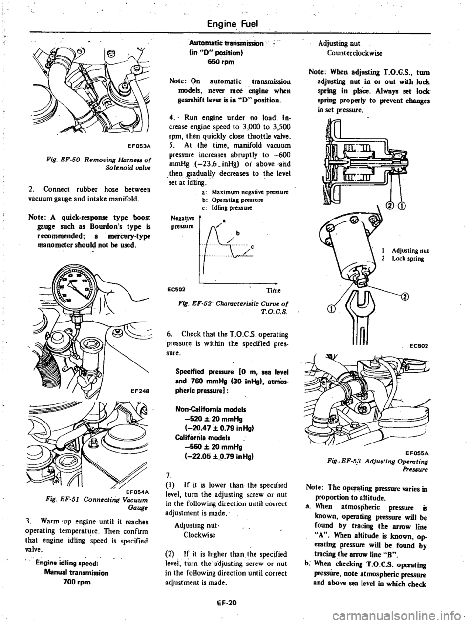
EF053A
Fig
EF
50
Removing
JWrneu
of
Solenoid
valve
2
Connect
rubber
hose
between
vacuum
gauge
and
intake
manifold
Note
A
quick
response
type
boost
gauge
such
as
Bourdon
s
type
is
recommended
a
mercury
type
manometer
should
not
be
used
3
Warm
up
engine
until
it
reaches
operating
temperature
Then
confirm
that
engine
idling
speed
is
specified
valve
Engine
idling
speed
Manual
transmission
700
rpm
Engine
Fuel
Automatic
transmission
in
0
position
650rpm
Note
On
automatic
transmission
models
never
race
engine
when
gearshift
lever
is
in
0
position
4
Run
engine
under
no
load
In
crease
engine
speed
to
3
000
to
3
500
rpm
then
quickly
close
throttle
valve
S
At
the
time
manifold
vacuum
pressure
increases
abruptly
to
600
rnmHg
23
6
inHg
or
above
and
then
gradually
decreases
to
the
level
set
at
idling
a
Maximum
negative
pressure
b
Operating
pressure
c
Idling
pressure
Nega
ive
pressure
EC502
Time
Fig
EF
52
Characteristic
Curve
of
T
O
C
S
6
Check
that
the
T
O
C
s
operating
pressure
is
within
the
specified
pres
sure
Specified
pressure
0
m
sea
level
end
760
mmHg
30
inHgl
atmOs
pheric
pressure
Non
Califomia
models
520
20
mmHg
20
47
0
79
inHg
California
models
560
20
mmHg
22
05
9
79
inHgl
7
I
If
it
is
lower
than
the
specified
level
turn
the
adjusting
screw
or
nut
in
the
following
direction
until
correct
adjustment
is
made
Adjusting
nut
Clockwise
2
If
it
is
higher
than
the
specified
levei
turn
the
adjusting
screw
or
nut
in
the
following
direction
until
correct
adjustment
is
made
EF
20
Adjusting
nut
Counterclockwise
Note
When
adjusting
T
O
C
S
turn
adjusting
nut
in
or
out
with
lock
spring
in
place
Always
set
lock
spring
properly
to
prevent
changes
in
set
pressure
Vo
1
Adjusting
nut
2
Lock
spring
n
EC802
EF055A
Fig
EF
53
Adjusting
Ope
llting
Pre
3ure
Note
The
operating
pressure
varies
in
proportion
to
altitude
a
When
atmospheric
pressure
is
known
operating
pressure
will
be
found
by
tracing
the
arrow
line
A
When
altitude
is
known
op
erating
pressure
will
be
found
by
tracing
the
arrow
line
B
b
When
checking
T
O
C
S
operating
pressure
note
atmospheric
pressure
and
above
sea
level
in
which
check
Page 117 of 548

Engine
Fuel
SERVICE
DATA
AND
SPECIFICATIONS
GENERAL
SPECIFICATIONS
CARBURETOR
California
models
Non
caJ
ifornia
model
Manual
tranlDlWion
Automatic
transmission
Manual
transmission
FU
model
utomatic
transmission
Type
DCH306
6t
DCH306
63
DCH306
60E
DCH306
67
DCH306
68
3
DCH306
69
1
DCH306
60
2
DCH306
12
4
Primary
Secondary
Primary
Secondary
Primuy
Secondary
Primary
Secondary
Primary
Secondary
Outer
diameter
26
1
02
30
1
18
26
1
02
30
1
18
26
1
02
30
1
18
26
1
02
30
1
18
26
1
02
30
1
18
mm
in
Venturi
diameter
23
0
9t
27
1
06
23
0
91
27
1
06
23
0
91
27
1
06
22
0
87
27
1
06
23
0
91
27
1
06
mm
in
Main
jet
107
145
107
1145
106
145
1107
145
105
1145
104
2
t04
4
Main
air
bleed
95
180
95
180
1110
80
65
1M
195
80
Slow
jet
1145
150
145
150
145
150
146
150
45
150
Powerjet
143
43
140
148
2
48
138
140
4
1
With
A15
engine
2
4
For
Canada
models
3
Common
to
models
with
A14
and
AlS
engines
except
Canada
INSPECTION
AND
ADJUSTMENT
A
T
C
AIR
CLEANER
Air
con
trol
valve
partially
opens
Air
control
valve
fully
opens
Oc
OF
Oc
F
38
to
54
100
to
129
Above
55
131
IDLE
COMPENSATOR
Idle
compensator
partially
opens
Bi
metal
No
I
Bi
metal
No
2
Idle
compensator
fully
opens
Bi
metal
No
I
Bi
metal
No
2
Oc
OF
60
to
70
140
to
158
70
to
80
158
to
176
Oc
OF
Above
70
158
Above
80
176
FUEL
PUMP
Fuel
pressure
Fuel
pump
capacity
kgfcm2
psi
cc
cu
in
min
at
rpm
0
27
3
8
450
27
46
1
000
EF
32
Page 153 of 548

REMOVAL
AND
INSTALLATION
I
Jack
up
the
car
Note
Apply
parking
brake
and
place
wheel
chocks
2
Remove
screws
securing
lower
shelter
of
catalytic
converter
Loosen
flange
bolt
connecting
catalytic
converter
to
front
and
rear
exhaust
tube
Catalytic
converter
assembly
can
then
be
taken
out
3
Installation
i
in
the
reverse
se
quence
of
removal
CAUTION
a
Be
careful
not
to
damage
catalytic
co
when
handliilg
b
Never
wet
catalyzer
with
water
oil
etc
t
J
Tightening
torque
Catalyti
converter
bolts
2
6
to
3
4
kg
m
19
to
25
ft
lb
Emission
Control
System
EC075A
EC076A
Fig
EC
103
Removing
Catalytic
Converter
INSPECTION
PrelimInary
In
pectlon
Vi
ually
check
condition
of
all
component
parts
including
hose
tubes
and
wires
replace
if
necessary
Refer
to
Air
Injection
System
for
inspection
EC
34
Catalytic
converter
Whether
catalytic
converter
is
nor
mal
or
not
can
e
checked
by
ob
serving
variation
in
CO
percentage
The
checking
procedure
is
as
follows
Apply
parking
brake
Shift
gears
into
Neutral
for
manual
transmis
sion
and
N
or
P
for
automatic
transmission
position
I
Adjust
engine
idling
speed
and
CO
percentage
Refer
to
Adjusting
Carburetor
Idle
RPM
and
Mixture
Ratio
for
adjustment
2
Race
engine
1
500
to
2
000
rpm
two
or
three
times
under
no
load
and
make
sure
that
specified
CO
percent
age
obtained
3
Remove
cap
and
connect
air
hose
to
air
check
valve
If
idling
speed
increases
readjust
it
to
specified
speed
with
throttle
adjusting
screw
4
Warm
up
engine
for
about
four
minutes
at
2
000
pm
under
no
load
S
Measure
Ci
percentage
at
idling
speed
After
stepAhas
been
complet
ed
wait
for
one
minute
before
making
CO
percentage
measurement
6
If
CO
percentage
measured
in
step
5
is
less
than
0
3
the
catalytic
converter
is
normaL
7
If
CO
percentage
measured
in
step
5
is
over
0
3
recheck
AJ
S
and
1
replace
air
check
valVe
The
perform
inspection
steps
4
and
S
8
If
CO
percentage
is
still
over
0
3
in
step
7
catalyt
iC
converter
i
mal
functioning
Replace
catalytic
con
verter
Page 199 of 548

REMOVAL
It
is
much
easier
to
remove
engine
and
transmission
as
a
single
unit
than
to
remove
alone
After
removal
engine
can
be
separated
from
the
transmission
assembly
WARNING
a
Place
wheel
chocks
in
fronl
of
front
wheels
and
in
rear
of
rear
wheels
b
Be
sure
to
hoist
engine
in
a
safe
manner
c
You
should
not
remove
engine
until
exhaust
system
has
com
pletely
cooled
off
Otherwise
you
may
burn
your
self
and
or
fire
may
break
out
in
fuel
line
Note
Fender
coven
should
be
used
to
protect
car
body
1
Disconnect
battery
ground
cable
from
battery
terminal
and
fusible
link
at
wire
connector
2
Remove
hood
as
follows
CAUTION
Have
an
assistant
help
you
so
as
to
prevent
damage
to
body
I
Mark
hood
hinge
locations
on
hood
to
facilitate
reinstallation
2
Support
hood
by
ltand
and
re
move
bolts
securing
it
to
hood
hinge
being
careful
not
to
let
hood
slip
when
bolts
are
removed
See
Fig
ER
2
3
Remove
hood
from
hood
hinge
f
Il
I
BF133A
Fig
ER
2
Removing
Hood
Remove
under
cover
Drain
radiator
coolant
and
engine
3
4
oil
5
Disconnect
upper
and
lower
hoses
from
radiator
and
disconnect
oil
cooler
hoses
automatic
transmission
only
6
Remove
four
bolts
securing
radia
Engine
Removal
Installation
tor
to
body
and
detach
radiator
after
removing
radiator
shroud
7
Remove
air
cleaner
assembly
from
carburetor
as
follows
1
Remove
fresh
air
duct
from
air
cleaner
2
Remove
hot
air
duct
from
air
cleaner
3
Loosen
air
cleaner
band
bolt
4
Disconnect
air
cleaner
to
air
pump
hose
at
air
cleaner
5
Disconnect
air
cleaner
ta
rocker
cover
hose
at
rocker
cover
6
Disconnect
air
cleaner
to
A
B
valve
hose
at
air
cleaner
7
Disconnect
air
cleaner
to
related
vacuum
hoses
at
air
cleaner
8
Disconnect
accelerator
control
wire
from
carburetor
9
Disconnect
the
following
cables
wires
and
hoses
Wire
to
auto
choke
heater
Wire
to
throttle
opener
cut
solenoid
or
throttle
switch
Wire
to
fuel
cut
solenoid
Wire
to
vacuum
switching
valve
High
tension
cable
between
igni
tion
coil
and
distributor
Battery
cable
to
starter
motor
Wire
to
distributor
Wire
to
thermal
transmitter
Wire
to
alternator
Engine
ground
cable
oil
pressure
switch
and
engine
harness
No
2
See
Fig
ER
3
o
1
Ground
cable
2
Engine
harness
No
2
3
Oil
pressure
switch
Fig
ER
3
EA368
Disconnecting
Cable
and
Wire
Fuel
hose
at
fuel
pump
and
fuel
return
hose
at
connection
Air
pump
air
cleaner
hose
Carbon
canister
hoses
Heater
inlet
and
outlet
hoses
if
so
equipped
ER
3
Vacuum
hose
of
brake
booster
at
intake
manifold
Air
conditioner
equipped
model
10
Remove
compressor
belt
To
remove
loosen
idler
pulley
nut
and
adjusting
bolt
1
Remove
air
pump
2
Remove
compressor
retaining
bolts
and
move
compressor
toward
fender
to
facilitate
removal
of
engine
Nole
Never
discharge
gas
from
com
pressor
while
work
is
being
per
formed
II
Compressor
EA478
Fig
ER
4
Location
of
Air
Compressor
3
Disconnect
vacuum
hose
of
air
conditioner
from
connector
of
intake
manifold
4
Remove
F
i
C
D
actuator
from
bracket
II
Remove
clutch
operating
cylin
der
from
clutch
housing
manual
trans
mission
only
dJ
Tightening
torque
Clutch
operating
cylinder
E
A3
to
clutch
housing
3
1
to
4
1
kg
22
to
30
ft
lbl
Fig
ER
5
Removing
Clutch
Operating
Cylinder