brake fluid DATSUN 210 1979 Service Manual
[x] Cancel search | Manufacturer: DATSUN, Model Year: 1979, Model line: 210, Model: DATSUN 210 1979Pages: 548, PDF Size: 28.66 MB
Page 9 of 548
Erigine
crankcase
EI
gine
cooling
system
Transmission
case
Final
drive
case
housing
Steering
gear
box
Fuel
tank
Air
conditioning
system
Refrigerant
Compressor
oil
f
tl
It
J
4
i
1
protect
the
catalytic
cop
verter
froitr
contamination
t
n
General
Information
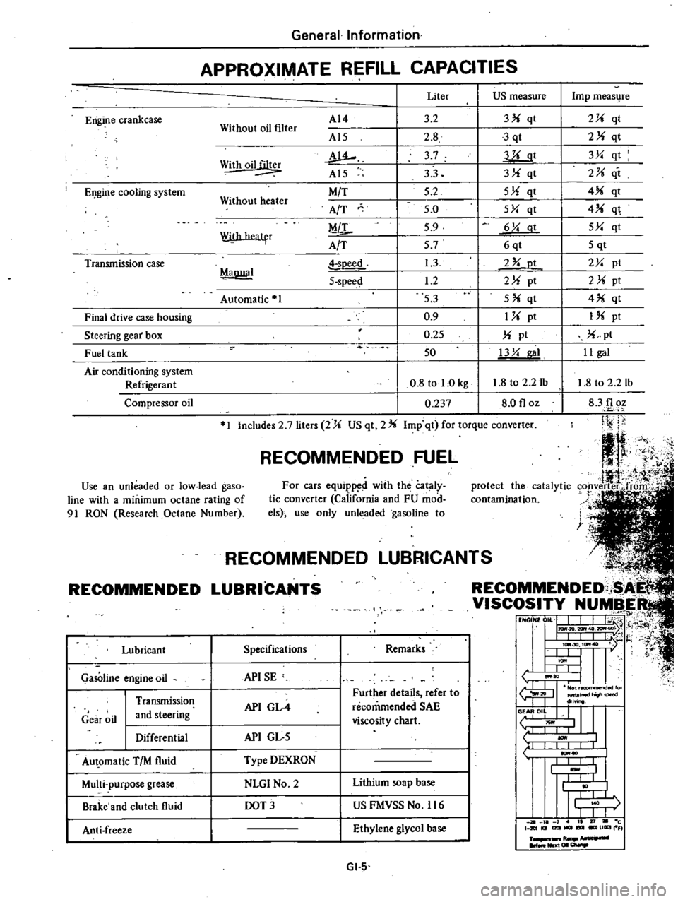
APPROXIMATE
REFILL
CAPACITIES
Without
oil
filter
AI4
Al5
w
Al5
M
T
AfT
MiL
A
T
Liter
US
measure
3
2
3
qt
2
8
3
qt
3
7
llLgt
33
3
qt
5
2
5
qt
5
0
5Y
qt
5
9
6
Y
at
57
6qt
1
3
2
Y
ot
1
2
2
pt
53
5
qt
0
9
1
pt
0
25
pt
50
13
Y
I
0
8
tol
Okg
1
8
to
2
2
1b
0
237
8
0
floz
Withoil
Without
heater
With
heatfr
MaDllal
soeed
5
spee
Automatic
1
1
Includes
2
7
liters
2
US
qt
2
Imp
qt
for
torque
converter
RECOMMENDED
FUEL
Use
an
unleaded
or
low
lead
gaso
line
with
a
minimum
octane
rating
of
91
RON
Research
Octane
Number
For
cars
equipp
d
with
the
Cataly
tic
converter
California
and
FU
mod
els
use
only
unleaded
gasoline
to
RECOMMENDED
Lubricant
GasOline
engine
oil
Gear
oil
Transmission
and
steering
Differential
Au
omatic
TIM
fluid
Multi
purpose
grease
Brake
and
clutch
fluid
Anti
freeze
L
NDED
LUBRICAN
COMMENDED
i
I
VISCOSITY
NUMBER
t1
NGON
0
L
J
I
j
H
I
IlL
I
t
l
I
lc
30
ItM
7
l
t
U
I
ItM
I
L
L
tJ
30
I
I
fu
JIl
inld
do
o
II
L
liOwl
1
I
I
1
10
I
I
I
I
t
I
I
j
r
I
I
J
1
21
l
1
I
71
c
DIUt
I2lItMOl
UGIIII
FI
R
NIl
I
01
a
Specifications
Remarks
APISE
API
GL4
Further
details
refer
to
recommended
SAE
viscosity
chart
API
GL
5
Type
DEXRON
NLGI
No
2
Lithium
soap
base
DOT
US
FMVSS
No
116
Ethylene
glycol
base
GI
5
Imp
meas4re
2
qt
2
qt
3Y
qt
2
it
4
qt
4
q
5Y
qt
5
qt
2Y
pt
2
pt
4
qt
I
pt
pt
II
gal
1
8
to
2
2
lb
83f1
oz
Ji
j
j
Page 204 of 548
CLUTCH
PEDAL
HEIGHT
I
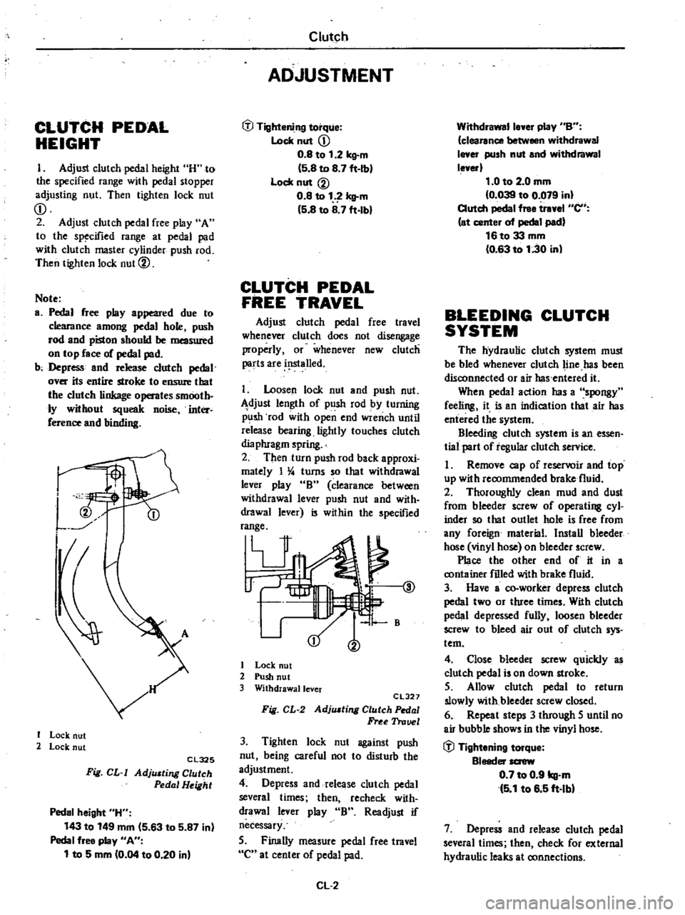
Adjust
clutch
pedal
height
H
to
the
specified
range
with
pedal
stopper
adjusting
nut
Then
tighten
lock
nut
CD
2
Adjust
clutch
pedal
free
play
A
to
the
specified
range
at
pedal
pad
with
clutch
master
cylinder
push
rod
Then
tighten
lock
nut
@
Note
a
Pedal
free
play
appeared
due
to
clearance
among
pedal
hole
push
rod
and
piston
should
be
measured
on
top
face
of
pedal
pad
b
Depress
and
release
clutch
pedal
over
its
entire
stroke
to
ensure
that
the
clutch
linkage
operates
smooth
ly
without
squeak
noise
inter
ference
and
binding
I
I
Lock
nut
2
Lock
nut
Cl325
Fig
CL
I
AdjlUting
Clutch
Pedal
Height
Pedal
height
H
143
to
149
mm
5
63
to
5
87
in
Pedal
free
play
An
1
to
5
mm
0
04
to
0
20
in
Clutch
ADJUSTMENT
tfl
Tightening
torque
Lock
nut
CD
0
8
to
1
2
kg
m
5
8
to
8
7
ft
Ib
Lock
nut
@
0
8
to
1
Icll
m
5
8
to
8
7
ft
lbl
CLUTCH
PEDAL
FREE
TRAVEL
Adjust
clutch
pedal
free
travel
whenever
clutch
does
not
disengage
properly
or
whenever
new
clutch
parts
are
i
lslalled
I
Loosen
lock
nut
and
push
nut
djust
length
of
push
rod
by
turning
p
lsh
rod
with
open
end
wrench
until
release
bearing
lightly
touches
clutch
dia
phragm
spring
2
Then
turn
push
rod
back
approxi
mately
I
4
turns
so
that
withdrawal
lever
play
B
clearance
between
withdrawal
lever
push
nut
and
with
drawal
lever
is
within
the
specified
range
V
@
1
B
I
Lock
nut
2
Push
nut
3
Withdrawallcver
CL327
Fig
CL
2
AdjlUting
Clutch
Pedal
Free
Trauel
3
Tighten
lock
nut
against
push
nut
being
careful
not
to
disturb
the
adjustment
4
Depress
and
release
clutch
pedal
several
times
then
recheck
with
drawal
lever
play
B
Readjust
if
necessary
5
Finally
measure
pedal
free
travel
C
at
center
of
pedal
pad
CL
2
Withdrawalle
er
play
nBn
clearance
between
withdrawal
I
er
push
nut
and
withdrawal
le
erl
1
0
to
2
0
mm
0
039
to
0
079
in
Clutch
pedal
free
tr
el
en
at
center
of
pedal
pad
16to33
mm
0
63
to
1
30
in
BLEEDING
CLUTCH
SYSTEM
The
hydraulic
clutch
system
must
be
bled
whenever
clutch
line
has
been
disconnected
or
air
has
entered
it
When
pedal
action
has
a
spongy
feeling
it
is
an
indication
that
air
has
entered
the
system
Bleeding
clutch
system
is
an
essen
tial
part
of
regular
clutch
service
I
Remove
cap
of
reservoir
and
top
up
with
recommended
brake
fluid
2
Thoroughly
clean
mud
and
dust
from
bleeder
screw
of
operating
cyl
inder
so
that
outlet
hole
is
free
from
any
foreign
material
Install
bleeder
hose
vinyl
hose
on
bleeder
screw
Place
the
other
end
of
it
in
a
container
filled
with
brake
fluid
3
Have
a
co
worker
depress
clutch
pedal
two
or
three
times
With
clutch
pedal
depressed
fully
loosen
bleeder
screw
to
bleed
air
out
of
clutch
sys
tem
4
Close
bleeder
screw
quickly
as
clutch
pedal
is
on
down
stroke
5
Allow
clutch
pedal
to
return
slowly
with
bleeder
screw
closed
6
Repeat
steps
3
through
5
until
no
air
bubble
shows
in
the
vinyl
hose
tfl
Tightening
torque
Bleeder
screw
0
7
to
0
9
kg
m
5
1
to
6
5
ft
lbl
7
Depress
and
release
clutch
pedal
several
times
then
check
for
external
hydraulic
leaks
at
connections
Page 205 of 548
Note
a
Brake
fluid
conlaining
air
is
white
and
has
visible
air
bubbles
b
Brake
fluid
containing
no
air
runs
out
of
bleeder
screw
in
a
1lO6d
stream
without
air
bubbles
c
Pay
close
attention
to
clutch
fluid
level
in
reservoir
during
bleeding
operation
Clutch
d
Pour
brake
fluid
into
reServoir
up
to
the
specified
level
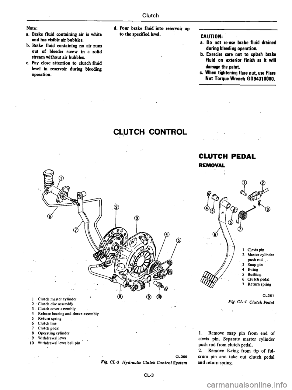
CLUTCH
CONTROL
Clutch
ma5ter
cylinder
2
Clutch
disc
assembly
3
Clutch
cover
assembly
4
Release
bearing
and
sleeve
assembly
5
Return
spring
6
Clutch
line
7
Clutch
pedal
8
Operating
cylinder
9
Withdrawal
lever
10
Withdrawal
lever
ball
pin
CAUTION
a
00
not
re
use
brake
fluid
drained
during
bleeding
operation
b
Exercise
care
not
to
splash
brake
fluid
on
exterior
finish
as
it
will
damage
the
paint
e
When
tightening
flare
nut
use
Flal
ll
Nut
Torque
Wrench
GG94310000
CLUTCH
PEDAL
REMOVAL
l
JF
j
1
Clevis
pin
2
Master
cylinder
push
rod
3
Snap
pin
4
E
ring
5
Bushfug
6
autch
pedal
7
Return
spring
j
CL351
Fig
CL
4
Clutch
Pedal
C
L369
Fig
CL
3
Hydraulic
Clutch
Control
System
CL
3
I
Remove
snap
pin
from
end
of
clevis
pin
Separate
master
cylinder
push
rod
from
clutch
pedal
2
Remove
E
ring
from
tip
of
ful
crum
pin
and
take
out
clutch
pedal
and
return
spring
Page 206 of 548
INSPEctiON
Check
clutch
pedal
parts
for
the
following
items
correcting
neces
sary
I
Bent
pedal
2
Weakened
return
spring
3
Worn
or
deformed
clevis
pin
and
fulcrum
bwhings
4
Cracks
at
welded
part
INSTAl1
ATION
To
install
clutch
pedal
reverse
the
order
of
removal
Observe
the
follow
ing
I
Apply
coating
of
recommended
multi
purpose
grease
to
sliding
por
tions
and
return
spring
Lt
of
I
ii
CL352
Fig
CL
5
Lubricating
Point
2
Fit
return
spring
in
hole
in
pedal
bracket
and
securely
fit
E
ring
in
slit
of
fulcrum
pin
3
Insert
clevis
pin
through
clutch
pedal
from
left
to
right
side
4
After
installing
clutch
pedal
check
the
clutch
pedal
height
AdjUst
if
necessary
Refer
to
Adjwtment
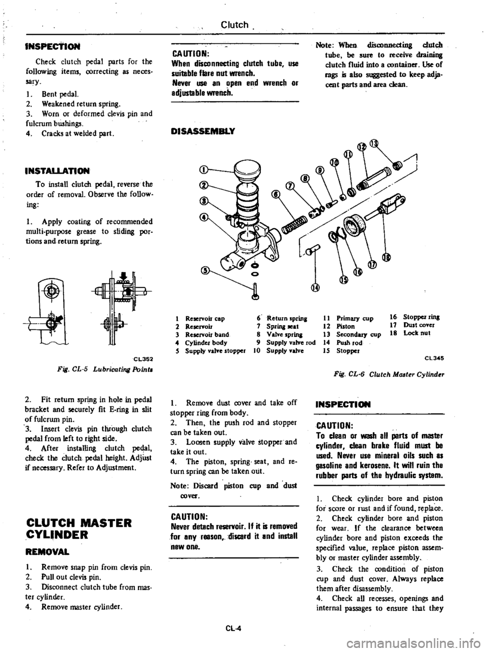
CLUTCH
MASTER
CYLINDER
REMOVAL
I
Remove
snap
pin
from
clevis
pin
2
Pull
out
clevis
pin
3
Disconnect
clutch
tube
from
mas
ter
cylinder
4
Remove
master
cylinder
Clutch
CAUTION
When
disconnecting
clutch
tube
use
suitable
flare
nut
wrench
Never
use
an
open
end
wrench
or
adjus1able
wrench
DISASSEMBLY
Note
When
disconnecting
dutch
tube
be
sure
to
receive
draioillll
clutch
fluid
into
a
container
Use
of
rags
is
also
suggested
to
keep
adja
cent
parts
and
area
clean
@
@
1
Reservoir
cap
6
Return
prina
11
Primary
cup
16
StOppel
rins
2
Reservoir
7
Sprina
seat
12
Piston
17
Dust
cover
3
Rescrvou
band
8
Valve
sprina
3
Secondary
cup
18
Lock
nut
4
Cylinder
body
9
Supply
valve
rod
14
Push
rod
5
Supply
yalYe
stopper
10
Supply
valve
15
Stopper
CL345
Fig
CL
6
Clutch
Mcuter
Cylind
r
I
Remove
dwt
cover
and
take
off
stopper
ring
from
body
2
Then
the
push
rod
and
stopper
can
be
taken
out
3
Loosen
supply
valve
stopper
and
take
it
out
4
The
piston
spring
seat
and
reo
turn
spring
can
be
taken
out
Note
Discard
piston
cup
and
dust
cover
CAUTION
Never
detach
reservoir
If
it
is
removed
for
any
reason
discard
it
and
instill
new
one
CL
4
INSPECTION
CAUTION
To
clean
or
wash
all
parts
of
masler
cylinder
clean
brake
fluid
must
be
used
Never
use
mineral
oils
such
as
gasoline
and
kerosene
It
will
ruin
tha
rubber
parts
of
tha
hydraulic
syslBm
I
Check
cylinder
bore
and
piston
for
score
or
rust
and
if
found
replace
2
Check
cylinder
bore
and
piston
for
wear
If
the
clearance
between
cylinder
bore
and
piston
exceeds
the
specified
value
replace
piston
assem
bly
or
master
cylinder
assembly
3
Check
the
condition
of
piston
cup
and
dust
cover
Always
replace
them
after
disassembly
4
Check
all
recesses
openings
and
internal
passages
to
ensure
that
they
Page 207 of 548
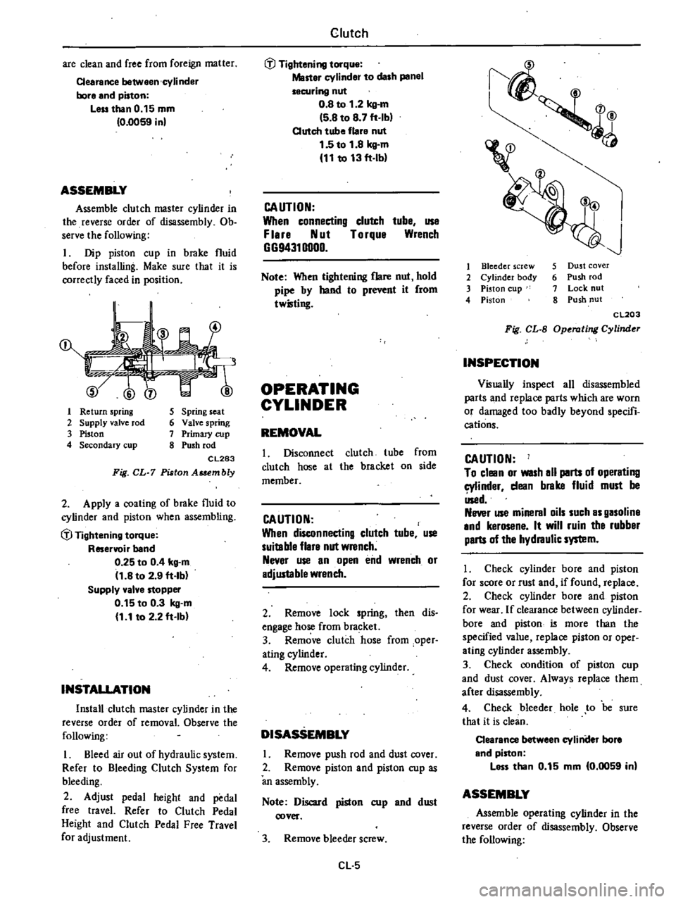
are
clean
and
free
from
foreign
matter
Cearance
between
cylinder
bore
and
piston
Leu
than
0
15
mm
0
0059
in
ASSEMBLY
Assemble
clutch
master
cylinder
in
the
reverse
order
of
disassembly
Ob
serve
the
following
I
Dip
piston
cup
in
brake
fluid
before
installing
Make
sure
that
it
is
correctly
faced
in
position
1
Return
spring
2
Supply
valve
rod
3
Piston
4
Secondary
cup
5
Spring
seat
6
Valve
spring
7
Primary
cup
8
Push
rod
CL283
Fig
CL
7
Piston
Asaembly
2
Apply
a
coating
of
brake
fluid
to
cylinder
and
piston
when
assembling
if
Tightening
torque
Reservoir
band
0
25
to
0
4
kg
m
11
8
to
2
9
ft
lb
Supply
valve
stopper
0
15
to
0
3
kg
m
1
1
to
2
2
ft
Ib
INSTALLATION
Install
clutch
master
cylinder
in
the
reverse
order
of
removal
Observe
the
following
I
Bleed
air
out
of
hydraulic
system
Refer
to
Bleeding
Clutch
System
for
bleeding
2
Adjust
pedal
height
and
pedal
free
travel
Refer
to
Clutch
Pedal
Height
and
Clutch
Pedal
Free
Travel
for
adjustment
Clutch
if
Tightening
torque
Master
cylinder
to
dash
panel
securing
nut
0
8
to
1
2
kg
m
5
8
to
8
7
ft
Ib
Clutch
tube
flare
nut
1
5
to
1
8
kg
m
11
to
13
ft
lb
CAUTION
When
connecting
clutch
tube
use
F
lere
Nut
Torque
Wrench
GG94310000
Note
When
tightening
flare
nut
hold
pipe
by
hand
to
r
it
from
twilling
OPERATING
CYLINDER
REMOVAL
I
Disconnect
clutch
tube
from
clutch
hose
at
the
bracket
on
side
member
CAUTION
When
disconnecting
clutch
tube
use
suitable
flare
nut
wrench
Never
use
an
open
end
wrench
or
adjustable
wrench
2
Remove
lock
spring
then
dis
engage
hose
from
bracket
3
Remove
clutch
hose
from
oper
ating
cylinder
4
Remove
operating
cylinder
DISASSEMBLY
Remove
push
rod
and
dust
cover
2
Remove
piston
and
piston
cup
as
an
assembly
Note
Discard
piston
cup
and
dust
cover
3
Remove
bleeder
screw
Cl
5
1
4
v
I
Bleeder
screw
2
Cylinder
body
3
Piston
cup
4
Piston
5
Dust
cover
6
Push
rod
7
Lock
nut
8
Push
nut
CL203
Fig
CL
B
Operating
Cylinder
INSPECTION
Visually
inspect
all
disassembled
parts
and
replace
parts
which
are
worn
or
damaged
too
badly
beyond
specifi
cations
CAUTION
To
clean
or
WISh
all
parts
of
operating
cylinder
dean
brake
fluid
must
be
Used
Never
use
mineral
oils
such
as
gasoline
and
kerosene
It
will
ruin
the
rubber
parts
of
the
hydraulic
system
I
Check
cylinder
bore
and
piston
for
score
or
rust
and
if
found
replace
2
Check
cylinder
bore
and
piston
for
wear
If
clearance
between
cylinder
bore
and
piston
i5
more
than
the
specified
value
replace
piston
or
oper
ating
cylinder
assembly
3
Check
condition
of
piston
cup
and
dust
cover
Always
replace
them
after
disassembly
4
Check
bleeder
hole
to
be
sure
that
it
is
clean
Clearance
between
cyliniler
bore
and
piston
less
than
0
15
mm
0
0059
in
ASSEMBLY
Assemble
operating
cylinder
in
the
reverse
order
of
disassembly
Observe
the
following
Page 208 of 548
t
Prior
to
lWembly
dip
a
new
piston
cup
in
clean
brake
fluid
To
install
piston
cup
on
piston
pay
par
ticular
auention
to
its
direction
2
Dip
cylinder
and
piston
in
clean
brake
fluid
before
assembly
INSTALLATION
Install
operating
cylinder
in
the
reverse
order
of
removal
Observe
the
following
1
Bleed
air
thoroughly
from
clutch
hydraulic
system
Refer
to
Bleeding
Clutch
System
for
bleeding
2
Adjust
clutch
pedal
free
travel
Refer
to
Clutch
Pedal
Free
Travel
for
adjustment
Note
a
Use
new
gasket
b
When
operating
cylinder
is
removed
from
or
instaUed
on
clutch
haus
ing
without
disconnecting
clutch
hose
from
operating
cylinder
loos
en
bleeder
screw
so
that
push
rod
mo
lightly
c
E
xer
e
care
not
to
p
or
wist
clutch
hose
Be
sure
to
install
clutch
hose
away
from
exhaust
tube
d
When
tightening
flare
nut
hold
pipe
by
hand
to
prevent
it
from
twisting
CAUTION
When
connecting
dutch
tuhe
uSe
Flare
Nut
Torque
Wrench
G694310000
@
Tightening
torque
Bleeder
screw
0
7
to
0
9
kg
m
5
1
to
6
5
ft
Ihl
Clutch
o
cylinder
to
clutch
housing
securing
bolts
3
1
to
4
1
kg
m
22
to
30
ft
lbl
Clutch
hose
to
operating
cyli
nder
1
7
to
2
0
kg
m
12
to
14
ft
lbl
Flare
nut
1
5
to
1
8
kg
m
11
to
13
ft
Ibl
CLUTCH
LINE
INSPECTION
Check
clutch
lines
tube
and
hose
for
evidence
of
cracks
deterioration
or
other
damage
Replace
if
necessary
If
leakage
occurs
at
or
around
joints
retighten
and
if
necessary
re
place
damaged
parts
REMOVAL
CAUTION
When
disconnecting
clutch
tube
use
suitable
flare
nut
wrench
Never
use
an
open
end
wrench
or
adjustable
wrench
1
Qisconnect
clutch
tube
from
clutch
hose
at
bracket
on
side
mem
ber
2
emove
lock
spring
then
disen
gage
hose
from
bracket
3
Remove
clutch
hose
from
oper
ating
cylinder
4
Disconnect
clutch
tube
from
mas
ter
cylinder
5
Remove
clamp
fIxing
clutch
tube
to
dash
panel
and
side
member
CL
6
INSTALLAnOlll
Wipe
the
opening
ends
of
hydraulic
line
to
remove
any
foreign
matter
before
malting
connections
I
Connect
clutch
tuhe
to
master
cylinder
with
flare
nut
2
Fix
clutch
tube
to
dash
panel
and
side
member
with
clamp
3
Then
tighten
flare
nut
@
Tightening
torque
Flar
nut
1
5
to
1
8
kg
m
11
to
13
ft
Ibl
2
InstaU
clutch
hose
on
operating
cylinder
with
a
gasket
in
place
Note
Use
new
gaslcet
@
Tightening
torque
1
7
to
2
0
kg
m
12
to
14ft
lbl
3
Engage
opposite
end
of
hose
with
bracket
InstaU
lock
spring
fIxing
hose
to
bracket
Note
a
When
tightening
flare
nut
hold
pipe
by
hand
to
prevent
it
from
twisting
b
Exercise
care
not
to
warp
or
twist
clu1ch
hose
4
Connect
clutch
tube
to
hose
with
flare
nut
and
tighten
it
5
Check
distance
between
clutch
line
and
adjacent
parts
especially
be
tween
hose
and
exhaust
tube
6
Bleed
air
out
of
hydraulic
system
Refer
to
Bleeding
Clutch
System
for
bleeding
CAUTION
When
tightening
flare
nut
use
Flare
Nut
Wrench
G
G9431
0000
Page 254 of 548

The
3N71
B
trammission
is
a
fully
automatic
unit
consisting
primarily
of
a
3
element
hydraulic
torque
converter
and
two
planetary
gear
sets
Two
multiple
disc
c1utclies
a
multiple
disc
brake
brake
band
and
one
way
clutch
provide
the
friction
elements
necessary
to
obtain
the
desired
function
of
the
two
planetary
gear
ets
A
hydraulic
control
system
is
used
to
operate
the
friction
elements
and
automatic
shift
controls
TORQUE
CONVERTER
The
torque
converter
is
attached
to
the
crankshaft
through
a
flexible
drive
plate
Heat
generat
in
the
t
rque
converter
is
dissipated
by
circulating
the
transmission
fluid
through
an
oil
to
water
type
cooler
in
the
radiator
lower
tank
The
welded
comtruction
of
the
torque
co
verter
prevents
di
3
ssembly
or
service
unless
highly
specialized
equipment
is
available
Qj
gJ
Autpmatic
Trimsmissi6n
DEScRIPTION
FLUID
RECOMMENDAnON
Use
DEXRON
type
automatic
transmission
fluid
only
IDENTIFICATION
NUMBER
Stamped
position
The
plate
is
attached
to
the
right
han
side
of
transmission
case
AT
M
Fig
AT
l
Identification
Number
Identification
of
number
arranaemanta
JAPAJllUTOIlATlC
TRAJISIIISSIO
C8
Ull
MODEL
X
0
12
3
NO
7
6
0
1
2
34
Number
designation
76
0
I
2
34
L
Serial
productioo
number
for
the
month
Month
of
production
1
Jan
2
Feb
X
Oct
Y
Nov
Z
Dec
Lut
IJgUre
denotins
the
year
A
D
IJ
III
J
W
f
r
lrr
G
1
Transmission
case
2
Oil
pump
3
Front
clutch
4
Band
brake
5
Rear
dutch
6
Front
planetary
geat
7
Rear
planetary
gear
8
One
way
clutch
9
Low
4
Reverse
brake
10
Oil
distributor
11
Governor
12
utput
shaft
13
Rear
extension
14
Oil
pan
IS
Control
valve
16
Input
shaft
17
Torque
converter
18
Converter
housi
19
Drive
pia
te
Tightening
torque
T
of
bolts
and
nuts
kg
m
ft
lb
@
T
4
to
5
29
to
36
@
T
14
to
16
101
to
116
@
T
4
5
to
5
5
33
to
40
@
T
0
6
to
0
8
4
3
to
5
8
@
T
0
5
to
0
7
3
6
to
5
1
T
2
0
to
2
5
14
to
18
@
T
1
3
to
1
8
9
to
13
@
T
0
55
ta
0
75
4
0
to
5
4
CD
T
0
25
to
0
35
1
8
to
2
5
AT312
Fig
AT
2
3N71B
Automatic
Trammiuion
AT
2
Page 255 of 548

Automatic
Transmission
HYDRAULIC
CONTROL
UNIT
AND
VALVES
The
hydraulic
or
a
tomatic
control
system
is
comprised
of
four
4
basic
groups
the
pressure
supply
system
the
pressure
regulating
system
the
flow
control
valves
and
the
friction
elements
PRESSURE
SUPPLY
SYSTEM
The
pressure
supply
system
consists
of
a
gear
type
oil
pwnp
driven
by
the
engine
through
the
torque
converter
The
pump
provides
pressure
for
aU
hydraulic
and
lubrication
needs
PRESSURE
REGULATOR
VALVES
The
pressure
regulating
valves
con
trol
the
output
pressure
of
the
oil
pump
Pre
ure
rellulator
valve
The
pressure
regulator
valve
con
trois
mainline
pressure
based
on
throttle
opening
for
the
operation
of
the
band
clutches
and
brake
Governor
valve
The
governor
valve
transmits
re
gulated
pressure
based
on
car
peed
to
the
shift
valves
to
control
upshifts
and
downshifts
Vacuum
throttle
valve
The
vacuum
throttle
valve
transmits
regulated
pressure
based
on
engine
load
vacuum
This
pressure
controls
the
pressure
regulator
valve
Also
this
pressure
is
applied
to
one
end
of
the
shift
valves
in
opposition
to
governor
pressure
which
acts
on
the
other
end
of
the
shift
valves
controlling
upshift
and
downshift
speeds
FLOW
CONTROL
VALVES
Manual
valve
The
manual
valve
is
moved
manual
Iy
by
the
car
operator
to
select
the
different
drive
ranges
1
2
ShHt
valve
The
1
2
shift
valve
automaticaIly
shifts
the
transmission
from
first
to
second
or
from
second
to
first
depend
ing
upon
governor
and
throttle
pres
sure
along
with
accelerator
position
solenoid
downshift
valve
See
Hy
draulic
Control
Circuits
Drive
2
2
3
ShHt
valve
The
2
3
shift
valve
automaticaIly
shifts
the
transmission
from
second
to
top
gear
or
from
top
to
second
de
pending
upon
governor
and
throttle
pressure
or
accelerator
position
sole
noid
downshift
valve
See
Hydraulic
Control
Circuits
Drive
3
Range
2
3
Tlmlnll
valve
For
2
3
shifts
a
restrictive
orifice
slows
the
application
fluid
to
the
front
clutch
while
the
slower
reacting
band
is
allowed
to
release
This
prevents
a
hard
2
3
or
3
2
shift
Under
heavy
load
however
the
engine
will
tend
to
run
away
during
the
2
3
or
3
2
shift
pause
therefore
a
2
3
timing
valve
using
throttle
and
governor
pressure
is
used
to
bypass
the
restrictive
orifice
during
such
heavy
load
conditions
Solenoid
down
hHt
valve
The
solenoid
downshift
valve
is
activated
electrically
when
the
ac
celerator
is
f1oor
d
causing
a
forced
downshift
from
top
to
second
top
to
first
or
second
to
first
gear
depending
upon
car
speed
governor
pressure
AT
3
Pre
ure
modified
valve
The
pressure
modifier
valve
assists
the
mainline
pressure
regulator
valve
in
lowering
mainline
pressure
during
high
speed
light
load
conditions
such
as
steady
speed
cruise
Governor
pres
sure
working
against
a
spring
opens
the
valve
which
aUows
modified
throt
tle
pressure
to
work
against
the
pres
sure
regulator
valve
spring
lowering
mainline
pressure
Lower
operating
pressure
under
light
load
reduces
oil
temperature
and
increases
transmis
sian
life
Throttle
back
up
valve
The
throttle
back
up
valve
assists
the
vacuum
throttle
valve
to
increase
line
pressure
when
the
manual
valve
is
shifted
either
to
2
or
I
range
Second
lock
valve
The
second
lock
valve
is
used
to
bypa
the
1
2
shift
valve
to
maintain
the
band
apply
pressure
in
2
posi
tion
The
valve
is
also
used
as
an
oil
passage
for
the
1
2
shift
valve
band
apply
pressure
in
D2
D3
and
12
Range
CLUTCHES
AND
BAND
SERVOS
The
servo
pistons
of
the
clutches
low
reverse
brake
and
band
are
moved
hydraulically
to
engage
the
clutches
brake
and
apply
the
band
The
clutch
and
brake
istons
are
released
by
spring
tension
and
band
piston
is
released
by
spring
tension
and
hy
draulic
pressure
Page 260 of 548
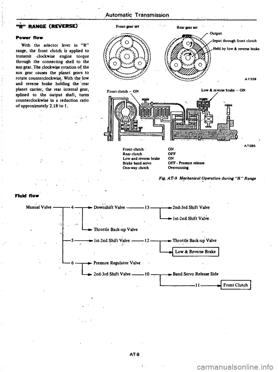
RANGE
REVERSE
Po
r
flow
With
the
selector
lever
in
R
range
the
front
clutch
is
applied
to
transmit
clockwise
engine
torque
through
the
connecting
shell
to
the
sull
gear
The
clockwise
otation
of
the
sun
gear
causes
the
planet
gears
to
rotate
counterclockwise
With
the
low
and
reverse
brake
holding
the
rear
planet
carrier
the
rear
internal
gear
splined
to
the
output
shaft
turm
counterclockwise
in
a
reduction
ratio
ofapproximately2
18
to
1
Fluid
flow
Manual
Valve
4
Automatic
Tninsmission
Front
gear
set
Rear
gear
ell
Output
Input
throush
front
clutch
Held
by
low
A
reverse
brake
AT329
lW
w
Y
Front
clutch
Rear
clutch
Low
and
reverse
brake
Brake
band
servo
On
way
clutch
5
Throttle
Back
up
Valve
Low
A
reverse
brake
ON
Downshift
Valve
1st
2nd
Shift
Valve
12
6
L
Pressure
Regulator
Valve
2nd
3rd
Shift
Valve
10
AT
8
AT085
ON
OFF
ON
OFF
Preuwe
release
o
ernmnin
F
AT
9
M
hanical
Operation
during
R
Range
13
2nd
3rd
Shift
Valve
L
1st
2nd
Shift
Valve
I
Throttle
Back
up
Valve
y
Low
Reve
Brake
Band
Servo
Release
Side
11
Front
Clut
h
I
Page 264 of 548
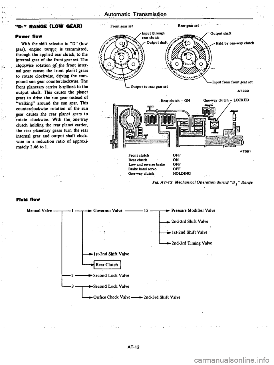
DI
RANGE
LOW
GEAR
Po
r
flow
With
the
shift
selector
in
0
low
gear
engine
torque
is
traJWnitted
through
the
applied
rear
clu
tch
to
the
internal
gear
of
the
front
gear
set
The
c1o
kwise
rotation
o
f
the
front
inter
naI
gear
causes
the
front
planet
gears
to
rotate
clockwise
driving
the
com
pound
sun
gear
counterclockwise
The
front
planetary
carrier
is
splined
to
the
output
shaft
This
cau
the
planet
gears
to
drive
the
sun
gear
instead
of
walking
around
the
sun
gear
This
counterclockwise
rotation
of
the
sun
gear
causes
the
rear
planet
gears
to
rotate
clockwise
With
the
one
way
clutch
holding
the
rear
planet
carrier
the
rear
planetary
gears
turn
the
rear
internal
gear
and
output
shaft
clock
wise
in
a
reduction
ratio
of
approxi
mately
2
46
to
L
Fluid
flow
Manual
Valve
2
3
Automatic
Transmission
Fiont
gear
set
Rear
gear
set
Input
t1uOllsh
rear
clutch
Output
shaft
Held
by
on
way
clutch
Input
from
front
gear
set
Output
to
real
gear
set
AT330
1
J
ld
AT081
Front
clutch
Reu
clutch
Low
and
revcrx
brake
Brake
band
servo
Onto
way
clutch
OFF
ON
OFF
OFF
HOLDING
Fig
AT
12
MochanicaIOp
rationduri
DJ
Ra
Governor
Valve
Pressure
Modifier
Valve
15
2nd
3rd
Shift
Valve
lst
2nd
Shift
Valve
2nd
3rd
Timing
Valve
1st
2nd
Shift
Valve
j
Rear
Clutch
I
Second
Lock
Valve
Second
Lock
Valve
LOrifice
Check
Valve
2nd
3rd
Shift
Valve
AT12