relay DATSUN 210 1979 User Guide
[x] Cancel search | Manufacturer: DATSUN, Model Year: 1979, Model line: 210, Model: DATSUN 210 1979Pages: 548, PDF Size: 28.66 MB
Page 457 of 548
Body
Electrical
System
ELECTRICAL
UNIT
OF
SIGNAL
SYSTEM
CAUTION
Before
startill1l
to
work
on
any
part
of
electrical
system
disconnect
battery
ground
cable
TURN
SIGNAL
SWITCH
Refer
to
combination
switch
HORN
RELAY
REMOVAL
AND
INSTALLATION
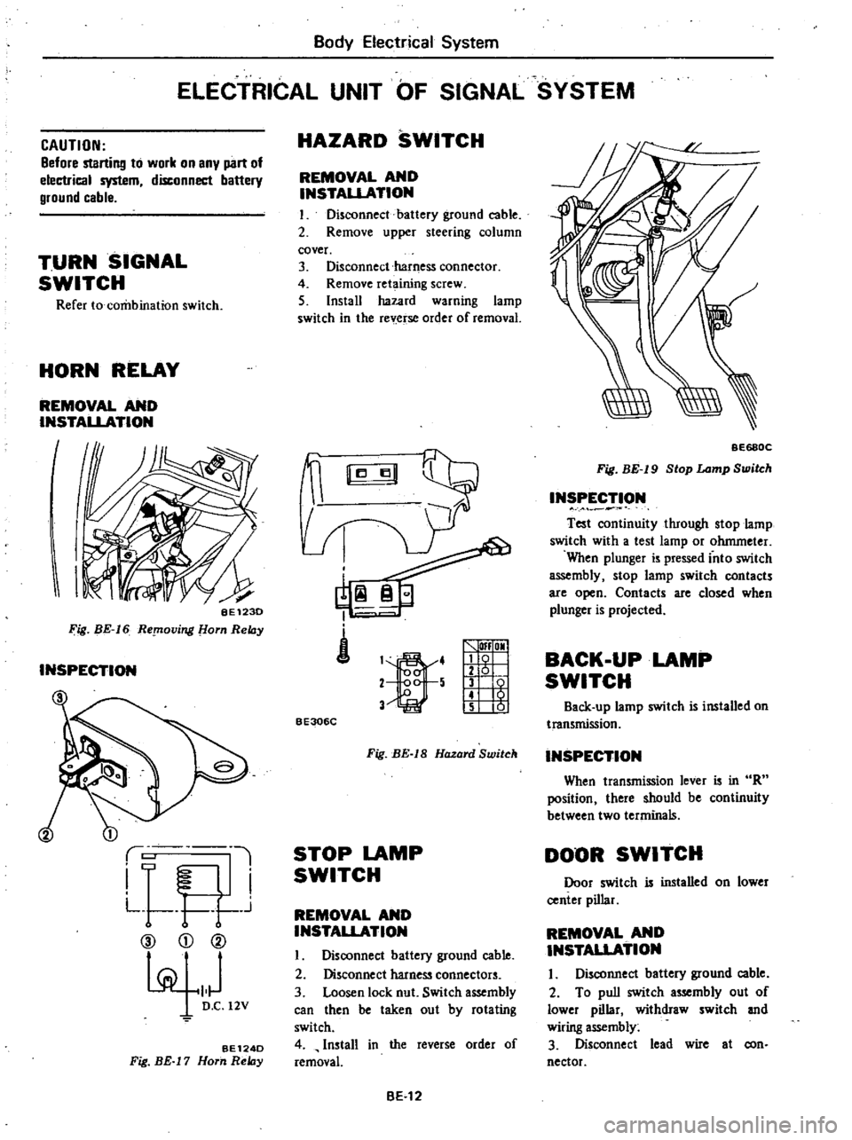
I
I
BE123D
Fig
BE
16
ReplOving
om
ReIDy
INSPECTION
1
i
L
l
I
F
I
L
t
r
j
CV
CD
@
pi
101
D
C
12V
BE124D
Fig
BE
17
Horn
ReIDy
HAZARD
SWITCH
REMOVAL
AND
INSTAUATION
I
Disconnect
battery
ground
cable
2
Remove
upper
steering
column
cover
3
Disconnect
harness
connector
4
Remove
ret
ining
screw
5
Install
hazard
warning
lamp
switch
in
the
rev
erse
order
of
removal
i
1
4
2
5
V
lfI
OMI
g
1
t
5
01
BE306C
Fig
BE
IS
Hazard
Switch
STOP
LAMP
SWITCH
REMOVAL
AND
INSTALLATION
I
Disoonnect
battery
ground
cable
2
Disconnect
harness
connectors
3
Loosen
lock
nut
Switch
assembly
can
then
be
taken
out
by
rotating
switch
4
Install
in
the
reverse
order
of
removal
BE
12
BE68QC
Fig
BE
19
Stop
Lamp
Switch
INSPECTION
Test
oontinuity
through
stop
lamp
switch
with
a
test
lamp
or
ohmmeter
When
plunger
is
pressed
into
switch
assembly
stop
lamp
switch
contacts
are
open
Contacts
are
closed
when
plunger
is
projected
BACK
UP
LAMP
SWITCH
Back
up
lamp
switch
is
installed
on
transmission
INSPECTION
When
transmission
lever
is
in
R
position
there
should
be
continuity
between
two
terminals
DOOR
SWITCH
Door
switch
is
installed
on
lower
center
pillar
REMOVAL
AND
INSTAUATION
I
Disconnect
battery
ground
cable
2
To
pull
switch
assembly
out
of
lower
pillar
withdraw
switch
and
wiring
assembly
3
Disconnect
lead
wire
at
con
nector
Page 468 of 548
Body
Electrical
System
Incorrect
Overlapped
area
Hea
t
wire
STARTING
SYSTEM
For
automatic
transmission
models
REPLACEMENT
AND
INSPECTION
Break
points
Inhibitor
switch
Refer
to
Section
AT
BE542
Inhibitor
relay
See
Fig
BE
B
Fig
BE
55
Incorrect
and
Correct
Deposition
of
Silver
Composition
HEATER
CAUTION
Before
starting
to
work
on
any
part
of
electrical
system
disconnect
battery
ground
cable
DESCRIPTION
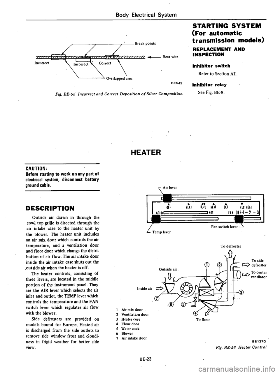
Air
lever
1
Off
CnID
p
lever
lEU
B
I
HUT
HDI
DEI
R
C
HUT
I
III
OFF
1
2
3
I
Fan
switch
lev
Outside
air
drawn
in
through
the
cowl
top
grille
is
directed
through
the
air
intake
case
to
the
heater
unit
by
the
blower
The
heater
unit
includes
an
air
mix
door
which
controls
the
air
temperature
and
a
ventilation
door
and
floor
door
which
change
the
distri
bution
of
air
flow
The
air
intake
door
inside
the
air
intake
case
shuts
out
the
outside
air
when
the
heater
is
off
The
heater
controls
consisting
of
three
levers
are
located
in
the
middle
portion
of
the
instrument
panel
They
are
the
AIR
lever
which
selects
the
air
inlet
and
outlet
the
TEMP
lever
which
controls
the
temperature
and
the
FAN
switch
lever
which
regulates
air
flow
with
the
blower
Side
defrosters
are
provided
on
models
bound
for
Europe
Heated
air
is
discharged
from
the
side
outlets
to
remove
side
window
frost
and
cloudi
ness
in
frigid
weather
for
better
side
view
Inside
air
To
defroster
fr
1
rf
To
side
r
2
t
defroster
1
U
C
D
i
LJ
t
@
6
5
Outside
air
1
Air
mix
door
2
Ventilation
door
3
Heater
core
4
Floor
door
5
Water
cock
6
Blower
7
Air
intake
door
To
Ooor
BE137D
Fig
BE
56
Heater
Control
BE
23
Page 472 of 548
IJi
Ir
c
r
I
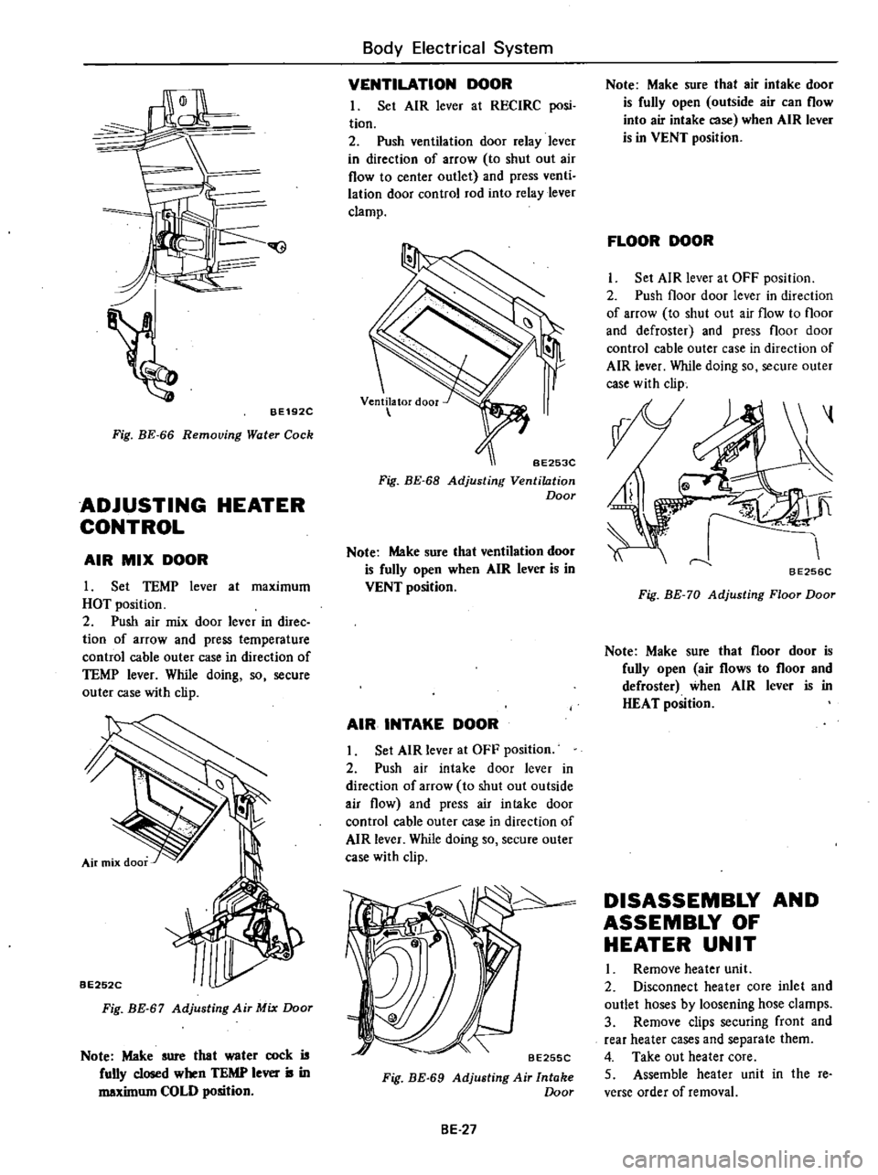
BE192C
Fig
BE
66
Removing
Water
Cock
ADJUSTING
HEATER
CONTROL
AIR
MIX
DOOR
I
Set
TEMP
lever
at
maximum
HOT
position
2
Push
air
mix
door
lever
in
direc
tion
of
arrow
and
press
temperature
control
cable
outer
case
in
direction
of
TEMP
lever
While
doing
so
secure
outer
case
with
clip
BE252C
Fig
BE
67
Adjusting
Air
Mix
Door
Note
Make
sure
that
water
cock
is
fully
closed
when
TEMP
lever
is
in
maxilnum
COLD
position
Body
Electrical
System
VENTILATION
DOOR
I
Set
AIR
lever
at
RECIRC
posi
tion
2
Push
ventilation
door
relay
lever
in
direction
of
arrow
to
shut
out
air
flow
to
center
outlet
and
press
venti
lation
door
control
rod
into
relay
lever
clamp
BE253C
Fig
BE
68
Adjusting
Ventilation
Door
Note
Make
sure
that
ventilation
door
is
fully
open
when
AIR
lever
is
in
VENT
position
AIR
INTAKE
DOOR
Set
AIR
lever
at
OFF
position
2
Push
air
intake
door
lever
in
direction
of
arrow
to
shut
out
outside
air
flow
and
press
air
intake
door
control
cable
outer
case
in
direction
of
AIR
lever
While
doing
so
secure
outer
case
with
clip
BE255C
Fig
BE
69
Adjusting
Air
Intake
Door
BE
27
Note
Make
sure
that
air
intake
door
is
fully
open
outside
air
can
flow
into
air
intake
case
when
AIR
lever
is
in
VENT
position
FLOOR
DOOR
Set
AIR
lever
at
OFF
position
2
Push
floor
door
lever
in
direction
of
arrow
to
shut
out
air
flow
to
floor
and
defroster
and
press
floor
door
control
cable
outer
case
in
direction
of
AIR
lever
While
doing
so
secure
outer
case
with
clip
BE256C
Fig
BE
70
Adjusting
Floor
Door
Note
Make
sure
that
floor
door
is
fully
open
air
flows
to
floor
and
defroster
when
AIR
lever
is
in
HEAT
position
DISASSEMBLY
AND
ASSEMBLY
OF
HEATER
UNIT
Remove
heater
uni
t
2
Disconnect
heater
core
inlet
and
outlet
hoses
by
loosening
hose
clamps
3
Remove
clips
securing
front
and
rear
heater
cases
and
separate
them
4
Take
out
heater
core
5
Assemble
heater
unit
in
the
re
verse
order
of
removal
Page 473 of 548
Body
Electdcal
System
INSPECTION
Check
the
following
items
if
blower
motor
fails
to
rotate
FUSE
To
check
for
burned
out
fuse
use
the
same
procedure
as
that
for
ordina
ry
fuses
with
a
circuit
tester
or
test
lamp
BLOWER
MOTOR
POWER
SUPPLY
Disconnect
blower
motor
harness
to
connect
main
harness
2
Connect
one
test
lamp
lead
wire
i
I
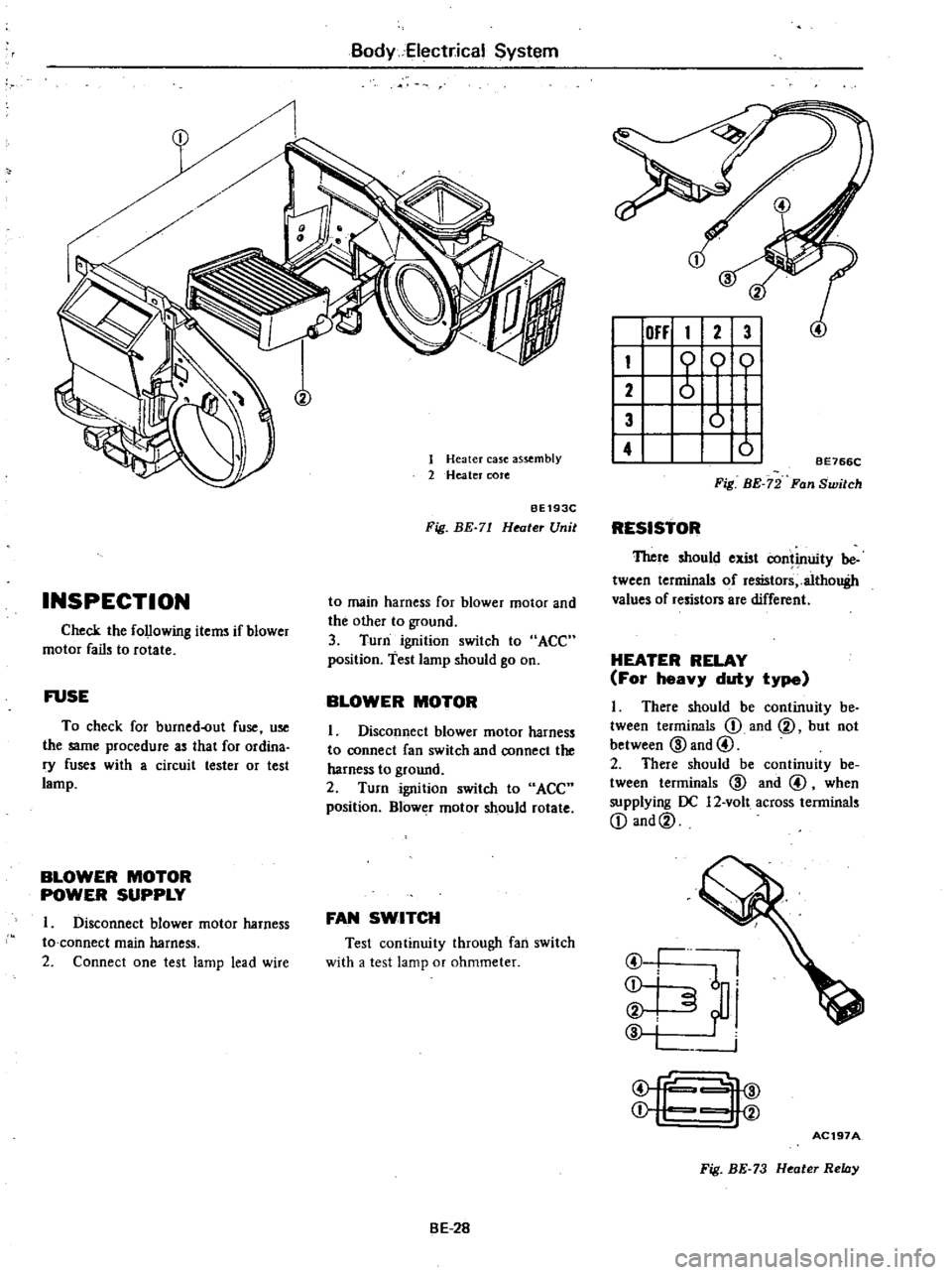
Heater
case
as
mbly
2
Heater
cote
BE193C
Fig
BE
71
Heater
Unit
to
main
harness
for
blower
motor
and
the
other
to
ground
3
Turn
ignition
switch
to
ACC
position
test
lamp
should
go
on
BLOWER
MOTOR
1
Disconnect
blower
motor
harness
to
connect
fan
switch
and
connect
the
harness
to
ground
2
Turn
ignition
switch
to
ACC
position
Blower
motor
should
rotate
FAN
SWITCH
Test
continuity
through
fan
switch
with
a
test
lamp
or
ohmmeter
BE
2B
OFF
1
2
3
I
1
0
01
2
I
3
0
I
4
01
BE766C
Fig
BE
72
Fan
Switch
RESISTOR
TItere
should
exist
continuity
be
tween
terminals
of
resistors
althouBh
values
of
resistors
are
different
HEATER
RELAY
For
heavy
duty
type
I
There
should
be
continuity
be
tween
terminals
D
and
@
but
not
between
@
and
@
2
There
should
be
continuity
be
tween
terminals
@
and
@
when
supplying
OC
12
volt
across
terminals
D
and@
I
@
I
I
j
i
i
@
fc
4@
j
I
V
AC197A
Fig
BE
73
Heater
Relay
Page 474 of 548
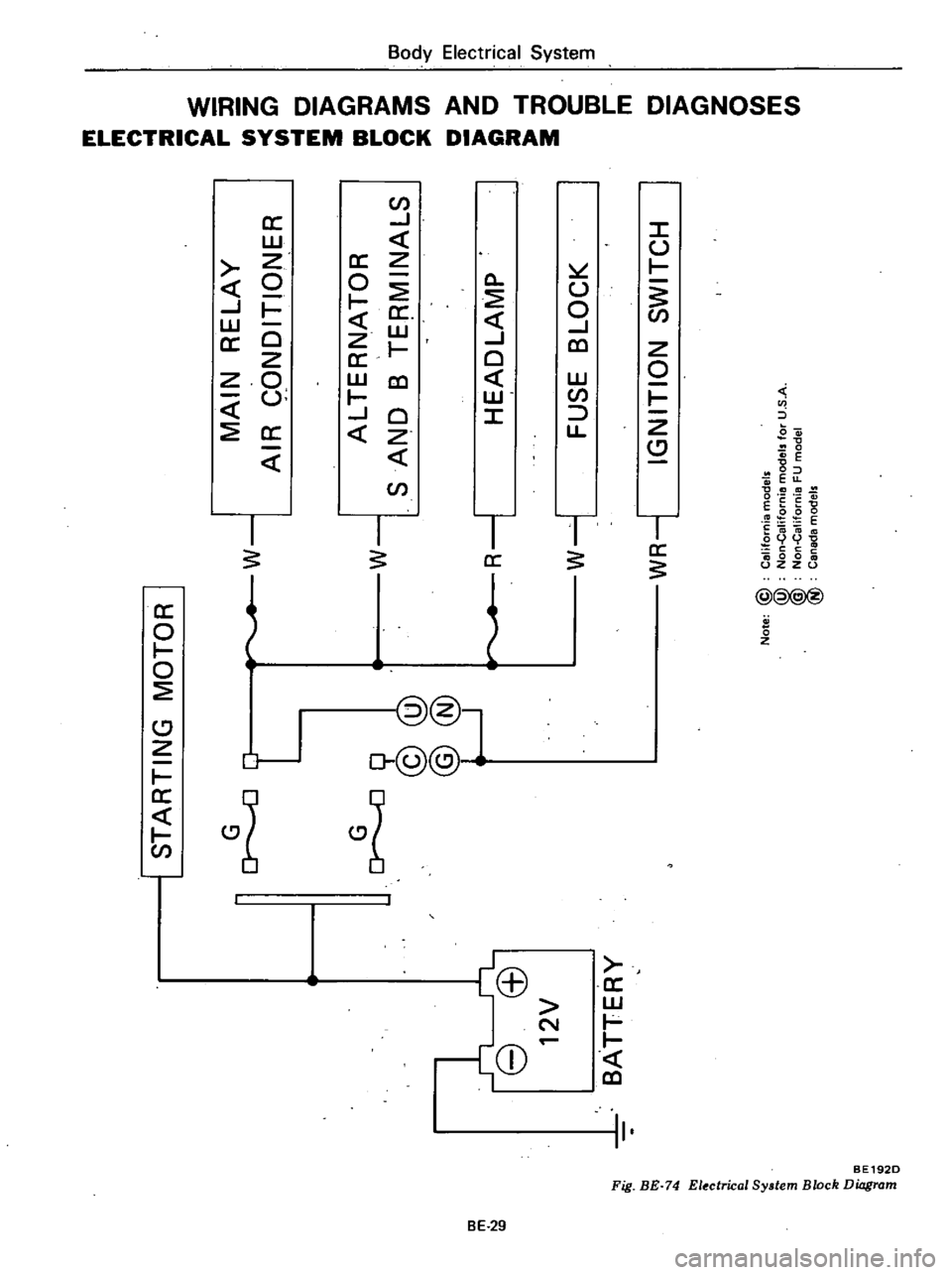
m
ii
I
ll
i
f
r
3
0
tl
i
a
iO
3
o
J
r
L
8
ffi
12V
BATTERY
I
STARTING
MOTOR
I
I
G
0
0
9
@@
@@
L
J
W
MAIN
RELAY
AIR
CONDITIONER
w
ALTERNATOR
SAND
B
TERMINALS
HEADLAMP
FUSE
BLOCK
I
WR
1
IGNITION
SWITCH
R
1
Note
@
i
W
Californta
models
Non
alifornt8
models
for
U
S
A
Non
CaliforOlB
FU
model
Canada
models
II
II
n
I
a
n
e
xI
ltZ
O
C
It
10
II
I
l
C
m
xl
0
l
OJ
3
0
n
CJ
II
m
al
CD
Z
0
2
a
t
CIl
xI
I
0
c
l
OJ
3
m
2
l
C
Z
o
CJ
m
CJ
Page 489 of 548
cIo
CD
m
t
tl
3
Cl
4
Ii
ii
C
l
I
i
I
ll
g
toom
a
ll
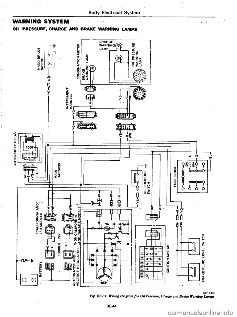
CALIFORNIA
ANO
BATTERY
FU
MOOELS
R
G
ff
w
G
M
wr
N
Q
WR
ALTERNATOR
ANO
IC
NON
cALIFOR
IA
VOLTAGE
REGULATOR
ANO
CANAOA
MO
S
I
fh
WR
B
i
W
i
C
@
J
W
l
9
i
j
@
Q
B
LB
OIL
PRESSURE
SWITCH
0
I
I
l
lOCI
OfflACC
OH
SI
Ys
j
D
01
mQ
IS
i
I
l
I
s
II
10
J
J
SWITCH
IGNITION
iji
BY
wr
1
I
1
IW
BRAKE
FLUIO
LEVEL
SWITCH
Ot
o
BJ
JO
0
Y
l
I
AUTO
cHOKE
RELAY
V
I
r
I
MAIN
HARNESS
FUSE
BLOCK
0
0
lOA
cr
L
lOA
cr
G
1
r
L
BL
HANO
BRAKE
SWITCH
G
J
i
INSTRUMENT
HARN
ESS
fG
YG
10
OMB
N
AT
qN
ETER
o
BRAKE
0
WARNING
LAMP
100
G
O
00
3
YB
f
G
WR
J
I
0
1
Fo
o
e
i
1
z
YB
OIL
PRESSURE
WARNING
LAMP
J
lI
a
Ill
z
11
1
III
Z
G
Ill
11
1
Ut
0
iUt
Ill
alii
11
1
I
a
i
l
i
Ill
Z
i
a
X
OJ
o
Cl
m
CD
o
CIl
l
3
Page 491 of 548
Body
Electrical
Sy
tem
Oil
pr
re
charg
and
brake
warillng
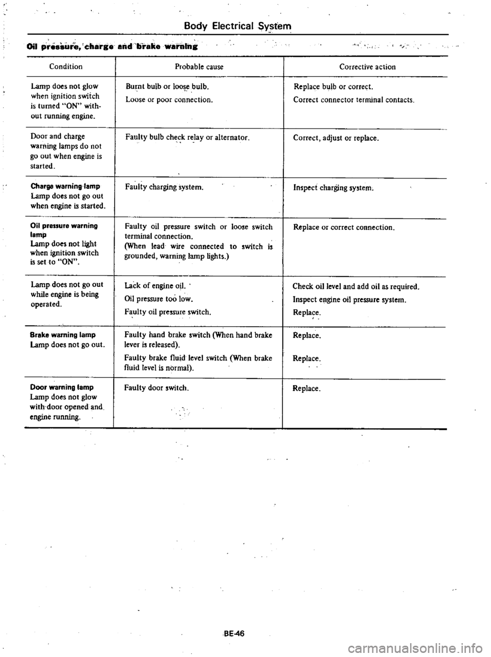
Condition
Lamp
does
not
glow
when
ignition
switch
is
turned
ON
with
out
running
engine
Door
and
charge
warning
lamps
do
not
go
out
when
engine
is
started
Charge
waming
amp
Lamp
does
not
go
out
when
engine
is
started
Oil
pressure
warning
lamp
Lamp
does
not
light
when
ignition
switch
is
set
to
ON
Lamp
does
not
go
out
while
engine
is
being
operated
Brake
warning
lamp
Lamp
does
not
go
out
Door
warning
lamp
Lamp
does
not
glow
with
door
opened
and
engine
running
Probable
cause
Burnt
bulb
or
loo
ebulb
Loose
or
poor
connection
Faully
bulb
check
relay
or
alternator
Faully
charging
system
Faully
oil
pressure
switch
or
loose
switch
terminal
connection
When
lead
wire
connected
to
switch
is
grounded
warning
lamp
lights
Lack
of
engine
oil
Oil
pressure
too
low
Faully
oil
pressure
switch
Faulty
hand
brake
switch
When
hand
brake
lever
is
released
Faully
brake
fluid
level
switch
When
brake
fluid
level
is
normal
Faully
door
switch
BE
46
Corrective
action
Replace
bulb
or
correct
Correct
connector
terminal
contacts
Correct
adjust
or
replace
Inspect
charging
system
Replace
or
correct
connection
Check
oil
level
and
add
oil
as
required
Inspect
engine
oil
pressure
system
Replace
Replace
Replace
Replace
Page 498 of 548
Body
Electrical
System
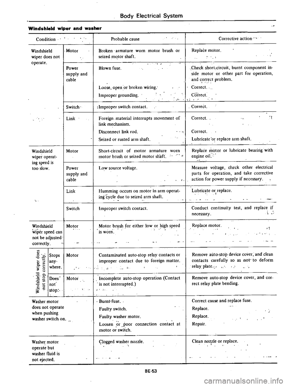
Condition
Windshield
wiper
and
washer
Probable
cause
Windshield
Motor
wiper
does
not
operate
Windshield
wiper
operat
ing
speed
is
too
slow
Power
supply
and
cable
Switch
Link
Motor
Power
supply
and
cable
Link
Switch
Windshield
Motor
wiper
speed
can
not
be
adjusted
correctly
o
o
fi
5
2
0
E
0
0
Stops
any
where
Does
not
stop
Washer
motor
does
not
operate
when
pushing
washer
switch
on
Washer
motor
operate
bu
t
washer
fluid
is
not
ejected
Motor
Motor
Broken
armature
worn
motor
brush
or
seized
m
tor
shaft
Blown
fuse
Loose
open
or
broken
wiring
Improper
grounding
Improper
switch
contact
Foreign
material
interrupts
movement
of
link
mechanism
Disconnect
link
rod
Seized
or
rusted
arm
shaft
Short
circuit
of
motor
armature
worn
motor
brush
or
seized
motor
snaft
Low
source
voltage
Humming
occurs
on
motor
in
arm
operat
infcycle
due
to
seized
arm
shaft
Improper
switch
contact
Motor
brush
for
either
low
or
high
speed
is
worn
Contaminated
auto
stop
relay
contacts
or
improper
contact
due
to
foreign
matter
Incomplete
auto
stop
operation
Contact
is
not
interrupted
Burnt
fuse
Faulty
switch
Faulty
washer
motor
Loosen
or
poor
connection
contact
at
motor
or
switch
logged
washer
nozzle
BE
53
Corrective
action
Replace
motor
Checkshort
circuit
burnt
component
in
side
motor
or
other
part
for
operation
and
corr
ct
problem
Correct
Correct
I
t
Correct
Correct
Correct
Lubricate
or
replace
arm
shaft
Replace
motor
or
lubricate
bearing
with
engine
oil
Measure
voltage
check
other
electrical
parts
for
operation
and
take
corrective
action
for
power
supply
if
necessary
Lubricate
or
replace
Conduct
continuity
test
and
replace
if
necessary
Replace
motor
Remove
auto
stop
device
cover
and
clean
contacts
carefully
so
as
not
to
deform
relay
plate
Remove
auto
stop
device
cover
and
cor
rect
relay
plate
bending
Correct
cause
and
replace
fuse
Replace
Replace
Repair
Clean
nozzle
or
replace
I
Page 499 of 548
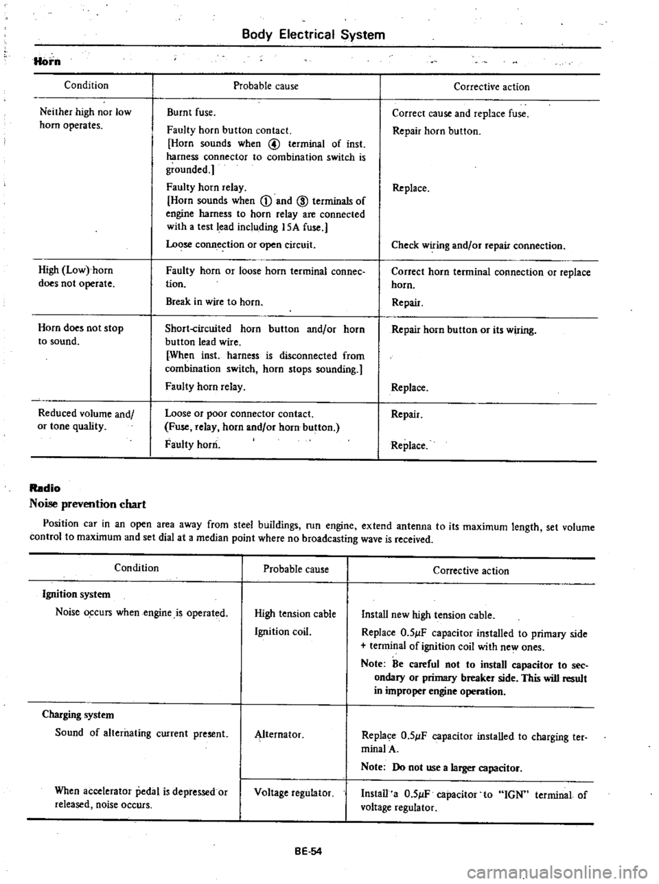
Horn
Condition
Neither
high
nor
low
horn
operates
High
Low
horn
does
not
operate
Horn
does
not
stop
to
sound
Reduced
volume
and
or
tone
quality
Body
Electrical
System
Probable
cause
Burnt
fuse
Faulty
horn
button
contact
Horn
sounds
when
@
terminal
of
inst
harness
connector
to
combination
switch
is
grounded
Faulty
horn
relay
Horn
sounds
when
CD
and
ID
terminals
of
engine
harness
to
horn
relay
are
connected
with
a
test
lead
including
15A
fuse
Lo
se
conn
ection
or
open
circuit
Faulty
horn
or
loose
horn
terminal
connee
tion
Break
in
wire
to
horn
Short
circuited
horn
button
and
or
horn
button
lead
wire
When
inst
harness
is
disconnected
from
combination
switch
horn
stops
sounding
Faulty
horn
relay
Loose
or
poor
connector
contact
Fuse
relay
horn
and
or
horn
button
Faulty
horn
Corrective
action
Correct
cause
and
repbce
fuse
Repair
horn
button
Replace
Check
wiring
and
or
repair
connection
Correct
horn
terminal
connection
or
replace
horn
Repair
Repair
horn
button
or
its
wiring
Replace
Repair
Replace
Radio
Noise
prevention
chart
Position
car
in
an
open
area
away
from
steel
buildings
run
engine
extend
antenna
to
its
maximum
length
set
volume
control
to
maximum
and
set
dial
at
a
median
point
where
no
broadcasting
wave
is
received
Condition
Probable
cause
Ignition
system
Noise
o
curs
when
engine
is
operated
High
tension
cable
Ignition
coil
Charging
system
Sound
of
alterilating
current
present
Alternator
When
accelerator
pedal
is
depressed
or
released
noise
occurs
Voltage
regulator
BE
54
Corrective
action
Install
new
high
tension
cable
Replace
O
5
lF
capacitor
installed
to
primary
side
terminal
of
ignition
coil
with
ne
ones
Note
Be
careful
not
to
install
capacitor
to
see
ondary
or
primary
breaker
side
This
will
result
in
improper
engine
operation
Replace
O
5
lF
capacitor
installed
to
charging
ter
minalA
Note
Do
not
use
a
larger
capacitor
Install
a
O
5
lF
capacitor
to
IGN
terminal
of
voltage
regulator
Page 502 of 548
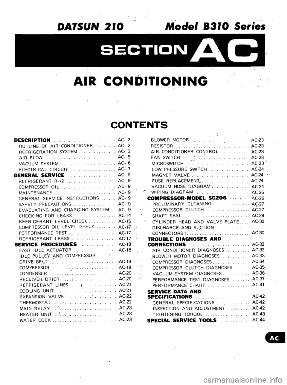
DATSUN
210
Model
8310
Series
SECTIONAC
AIR
CONDITIONING
CONTENTS
DESCRIPTION
OUTLINE
OF
AIR
CONDITIONER
REFRIGERATION
SYSTEM
AIR
FLOW
VACUUM
SYSTEM
ELECTRICAL
CIRCUIT
GENERAL
SERVICE
REFRIGERANT
R
12
COMPRESSOR
OIL
MAINTENANCE
GENERAL
SERVICE
INSTRUCTIONS
SAFETY
PRECAUTIONS
EVACUATING
AND
CHARGING
SYSTEM
CHECKI
NG
FOR
LEAKS
REFRIGERANT
LEVEL
CHECK
COMPRESSOR
OIL
LEVEL
OHECK
PERFORMANCE
TEST
REFRIGERANT
LEAKS
SERVICE
PROCEDURES
FAST
IDLE
ACTUATOR
IDL
E
PULLEY
AND
COMPRESSOR
DRIVE
BELT
COMPR
ESSOR
CONDENSER
RECEIV
ER
DRIER
REFRIGERANT
LINES
I
COOLING
UNIT
EXPANSION
VALVE
THERMOSTAT
MAIN
RELAY
HEATER
UNIT
WATER
COCK
AC
2
AC
2
AC
3
AC
5
AC
6
AC
7
AC
9
AC
9
AC
9
AC
9
AC
9
AC
9
AC
1
AC14
AC15
AC
17
AC17
AC17
AC18
AC1B
AC19
AC19
AC
20
AC
20
AC
21
ACc21
AC
22
AC
22
AC
23
AC
23
AC
23
BLOWER
MOTOR
RESISTOR
AIR
CONDITIONER
CONTROL
FAN
SWITCH
MICROSWITCH
LOW
PRESSURE
SWITCH
MAGNET
VALVE
FUSE
REPLACEMENT
VACUUM
HOSE
DIAGRAM
WIRING
DIAGRAM
COMPRESSOR
MODEL
SC206
PRELIMINARY
CLEANING
COMPRESSOR
CLUTCH
SHAFT
SEAL
CYLINDER
HEAD
AND
VALVE
PLATE
DISCHARGE
AND
sU
CTiON
CONNECTORS
TROUBLE
DIAGNOSES
AND
CORRECTIONS
AIR
CONDITIONER
DIAGNOSES
BLOWER
MOTOR
DIAGNOSES
COMPRESSOR
DIAGNOSES
COMPRESSOR
CLUTCH
DIAGNOSES
VACUUM
SYSTEM
DIAGNOSES
PERFORMANCE
TEST
DIAGNOSES
PERFORMANCE
CHART
SERVICE
DATA
AND
SPECIFICATIONS
GENERAL
SPECIFICATIONS
INSPECTION
AND
ADJUSTMENT
TIGHTENING
TORQUE
SPECIAL
SERVICE
TOOLS
AC
23
AC
23
AC
23
AC
23
AC23
AC
24
AC
24
AC24
AC
24
AC
25
AC
26
AC
27
AC
27
AC
28
AC30
AC30
AC32
AC
32
AC
33
AC34
AC35
AC36
AC37
AC
41
AC
42
AC
42
AC
42
AC
43
AC
44