set clock DATSUN 210 1979 User Guide
[x] Cancel search | Manufacturer: DATSUN, Model Year: 1979, Model line: 210, Model: DATSUN 210 1979Pages: 548, PDF Size: 28.66 MB
Page 266 of 548

D2
RA
NGE
2ND
GEAR
Power
flow
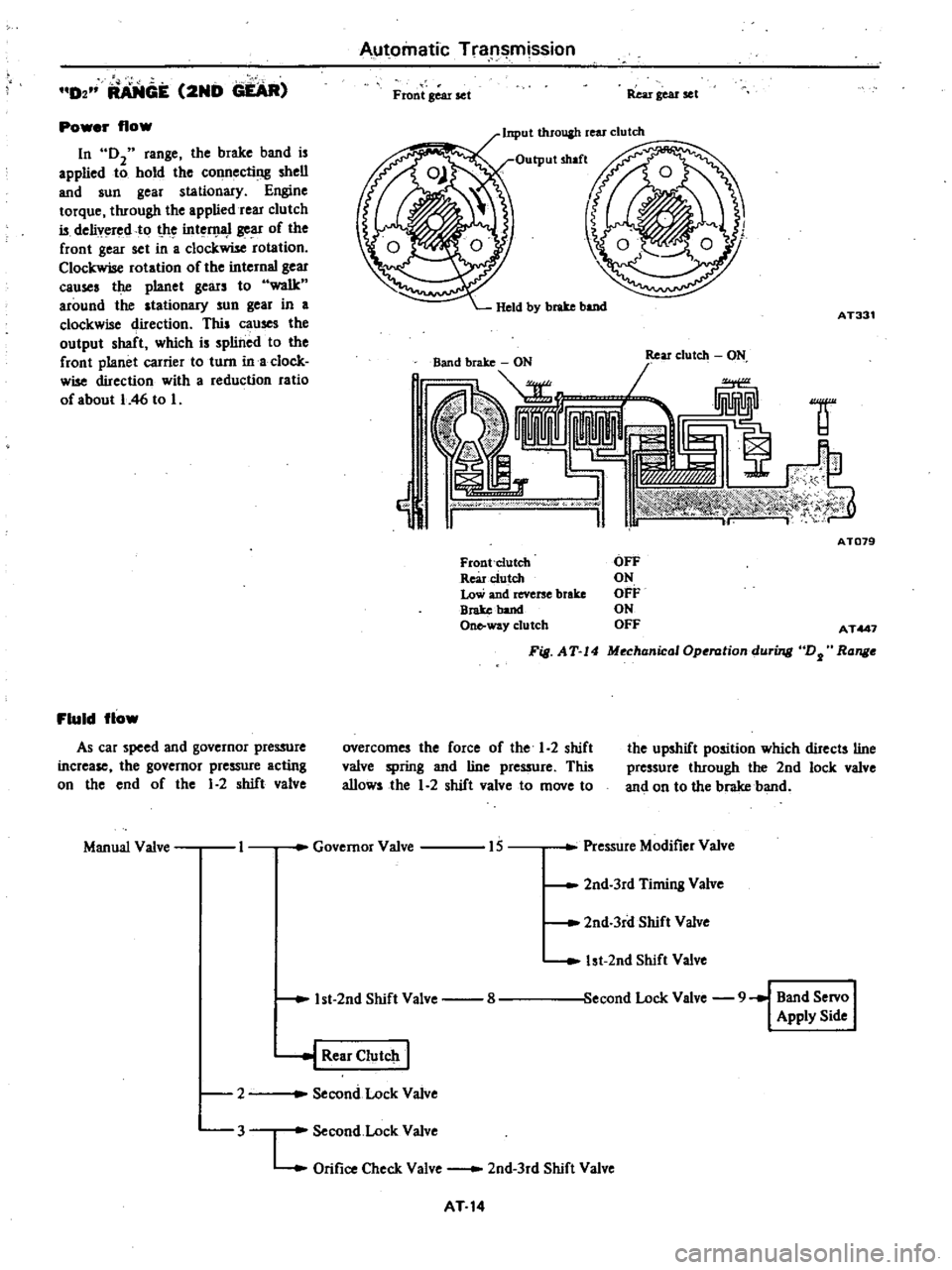
In
02
range
the
brake
band
is
applied
to
hold
the
connecting
shell
and
sun
gear
stationary
Engine
torque
through
the
applied
rear
clutch
is
delivered
to
t
he
int
D
1l
1
gear
of
the
front
gear
set
in
a
clockwise
rotation
Clockwise
rotation
of
the
internal
gear
causes
the
planet
gears
to
walk
around
the
stationary
sun
gear
in
a
clockwise
direction
This
causes
the
output
shaft
which
is
splined
to
the
front
planet
carrier
to
turn
ina
clock
wise
direction
with
a
reduction
ratio
of
about
I
46
to
I
Fluid
flow
As
car
speed
and
governor
pressure
increase
the
governor
pressure
acting
on
the
end
of
the
1
2
shift
valve
Manual
Valve
I
Automatic
Tra
l
mission
Front
Bear
set
Rear
gear
set
Input
throuah
rear
clutch
AT331
1f
j
cW
oo
w
I
ATD79
Front
Clutch
Rearc1utch
Low
and
reverse
brake
Broke
band
One
way
clutch
OFF
ON
OFF
ON
OFF
AT447
F
S
AT
14
MechanicalOperation
during
DJ
Range
overcomes
the
force
of
the
1
2
shift
valve
spring
and
line
pressure
This
allows
the
1
2
shift
valve
to
move
to
the
upshift
position
which
directs
line
pressure
through
the
2nd
lock
valve
and
on
to
the
brake
band
Governor
Valve
15
Pressure
Modifier
Valve
2nd
3rd
Timing
Valve
2nd
3rd
Shift
Valve
1st
2nd
Shift
Valve
econd
Lock
Valve
9
Band
Servo
I
Apply
Side
1st
2nd
Shift
Valve
8
l
Rear
CIutclt
I
Second
Lock
Valve
2
3
Second
Lock
Valve
L
Orifice
Check
Valve
2nd
3rd
Shift
Valve
AT
14
Page 268 of 548

Automatic
Transmission
D3
RANGE
3RD
GEAR
Front
gear
set
Rei
r
gear
set
Input
through
flODt
and
rear
clutches
Power
flow
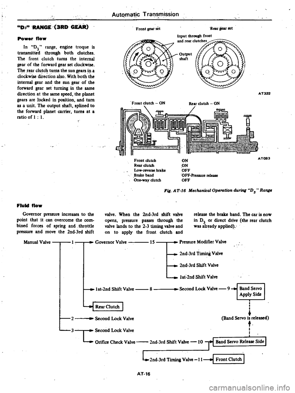
In
D3
range
engine
troque
is
transmitted
through
both
clutches
The
front
clutch
turns
the
internal
gear
of
the
forward
gear
set
clockwise
The
rear
clutch
turns
the
sun
gears
in
a
clockwise
direction
also
With
both
the
internal
gear
and
the
sun
gear
of
the
forward
gear
set
turning
in
the
same
direction
at
the
same
speed
the
planet
gears
are
locked
in
position
and
turn
as
a
unit
The
output
shaft
spIined
to
the
forward
planet
carrier
turns
at
a
ratio
of
L
Output
shaft
AT332
Front
clutch
ON
Ij
1f
Front
clutch
Rear
e1utd
Low
reverse
brake
Brake
band
On
way
clutch
ON
ON
OFF
OFF
Pressure
rdeaJe
OFF
A
T083
Fill
AT
I6
Mechanical
Operation
hiring
D
Ronge
Fluid
flow
Governor
pre
ure
increases
to
the
poinl
that
it
can
overcome
the
com
bined
forces
of
spring
and
throttle
pressure
and
move
the
2nd
3rd
shift
valve
When
the
2nd
3rd
shift
valve
opens
pressure
passes
through
the
valve
lands
to
the
2
3
timing
valve
and
on
to
apply
the
front
clutch
and
release
the
brake
band
The
car
is
now
in
D3
or
direct
drive
the
rear
clutch
was
already
applied
Manual
Valve
I
Governor
Valve
IS
Pressure
Modifier
Valve
2nd
3rd
Timin8
Valve
2nd
3rd
Shift
Valve
ht
2nd
Shift
Valve
1st
2nd
Shift
Valve
8
Second
Lock
Valve
9
Band
Servo
Apply
Side
2
i
I
I
Band
Servo
is
released
t
Second
Lock
Valve
L
Orifice
Check
Valve
2nd
3rd
Shift
Valve
10
r
Band
Servo
Rele
Side
I
L
2nd
3rd
Timing
Valve
I
I
I
Front
Clutch
I
J
Second
Lock
Valve
I
Rear
Clutch
I
3
AT
16
Page 406 of 548

Engine
Control
fuel
Exhaust
Systems
Non
California
models
except
FU
model
Automatic
transmission
equipped
models
@
REMOVAL
CALIFORNIA
MODELS
AND
FU
MODEL
I
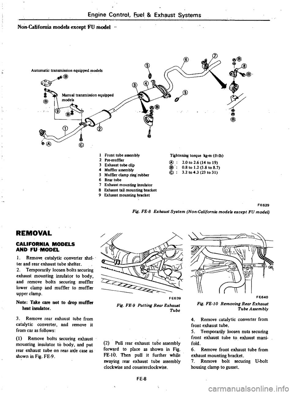
Remove
catalytic
converter
shel
ter
and
rear
exhaust
tube
shelter
2
Temporarily
loosen
bolts
securing
exhaust
mounting
insulator
to
body
and
remove
bolts
securing
muffler
lower
clamp
imd
muffler
to
muffler
upper
clamp
Note
Take
care
Dot
to
drop
muffler
heat
insulator
3
Remove
rear
exhaust
tube
from
catalytic
converter
and
remove
it
from
car
as
follows
I
Remove
bolts
securing
exhaust
mounting
insulator
to
body
and
put
rear
exhaust
tube
on
rear
axle
case
as
shown
in
Fig
FE
9
1
Front
tube
assembly
2
Pre
muff1er
3
Exhaust
tube
clip
4
Momer
wembly
5
Muffler
clamp
ring
rubber
6
Rear
tube
7
Exhaust
mounting
insulator
8
Exha
st
tail
mounting
bracket
9
Exhaust
mounting
1
ttacket
8@
@
4
wp
8
@
Tightening
torque
kg
m
ft
lb
@
2
0
to
2
6
14
to
t9
@
0
8
to
1
2
5
8
to
8
7
@
3
2
to
4
3
23
to
31
FE629
Fig
FE
B
E
haust
System
Non
California
mode
e
cept
FU
modet
FE639
Fig
FE
9
Putting
Rear
E
halUt
Tube
2
Pull
rear
exhaust
tube
assembly
forward
to
place
as
shown
in
Fig
FE
IO
Then
pull
it
further
while
swaying
rear
exhaust
tube
assembly
clockwise
and
counterclockwise
FE
B
II
F
E640
Fig
FE
IO
Removing
Rear
E
xhault
Tube
Assembly
4
Remove
catalytic
converter
from
front
exhaust
tube
5
Temporarily
loosen
nuts
securing
f
root
exhaust
tube
to
exhaust
mani
fold
6
Remove
front
exhaust
tube
from
exhaust
mounting
bracket
7
Remove
bolt
securing
V
bolt
housing
clamp
to
gusset
Page 466 of 548

t
Fig
BE
45
Speaker
Antenna
Remove
screws
fastening
upper
and
lower
antenna
supports
to
front
pillar
2
Install
antenna
in
the
reverse
order
of
removal
Feeder
cable
I
Disconnect
battery
ground
cable
2
Remove
antenna
3
Remove
front
pillar
molding
4
Remove
cluster
lid
A
5
Disconnect
feeder
cable
from
radio
receiver
6
Pull
out
feeder
cable
through
hole
in
front
pillar
7
Install
feeder
cable
in
the
reverse
order
of
removal
r
BE251C
Fig
BE
46
Antenna
and
Feeder
Cable
ADJUSTING
ANTENNA
TRIMMER
When
a
new
radio
receiver
antenna
or
feeder
cable
is
installed
antenna
trimmer
shoul
be
adjusted
Body
Electrical
System
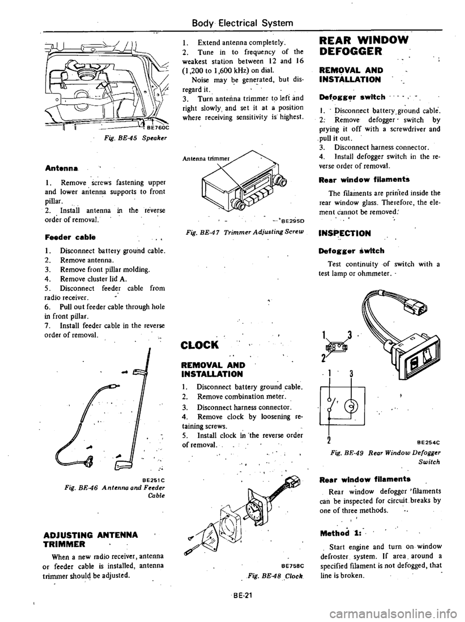
Extend
antenna
completely
2
Tune
in
to
frequency
of
the
weakest
station
between
12
and
16
I
200
to
1
600
kHz
on
dial
Noise
may
be
generated
but
dis
regard
it
3
Turn
anteiln3
trimmer
to
left
and
right
slowly
and
set
it
at
a
position
where
receiving
sensitivity
is
highest
BE29SD
Fig
BE
47
Trimmer
Adjusting
Screw
CLOCK
REMOVAL
AND
INSTALLATION
I
Disconnect
battery
ground
cable
2
Remove
combination
meter
3
Disconnect
harness
connector
4
Remove
clock
by
loosening
re
taining
screws
5
Install
clock
in
the
reverse
order
of
removal
r
Jf
rr
i1
b
Ii
f
7
8
eE758C
Fig
BE
48
Clock
BE
21
REAR
WINDOW
DEFOGGER
REMOVAL
AND
INSTALLATION
Def
ogg
r
switch
I
Disconfi
ect
battery
ground
cable
2
Remove
defogger
switch
by
prying
it
off
with
a
screwdriver
and
pull
it
out
3
Disconnect
harness
connector
4
Install
defogger
switch
in
the
reo
verse
order
of
removal
Rear
window
filaments
The
fIlaments
are
printed
inside
the
rear
window
glass
Therefore
the
ele
ment
cannot
be
removed
INSPECTION
Defogger
switch
Test
continuity
of
switch
with
a
test
lamp
or
ohmmeter
1
d
2
1
3
L
BE254C
Fig
BE
49
Rear
Window
Defogger
Switch
Rear
window
filaments
Rear
window
defogger
tfilaments
can
be
inspected
for
circuit
breaks
by
one
of
three
methods
Method
1
Start
engine
and
turn
on
window
defroster
system
If
area
around
a
specified
filament
is
not
defogged
that
line
is
broken